LEXUS LS430 2003 Factory Repair Manual
Manufacturer: LEXUS, Model Year: 2003,
Model line: LS430,
Model: LEXUS LS430 2003
Pages: 4500, PDF Size: 87.45 MB
LEXUS LS430 2003 Factory Repair Manual
LS430 2003
LEXUS
LEXUS
https://www.carmanualsonline.info/img/36/57050/w960_57050-0.png
LEXUS LS430 2003 Factory Repair Manual
Trending: intake manifold inlet, injection, navigation, key battery, wiring diagram, Signal compressor condition, clutch
Page 1631 of 4500
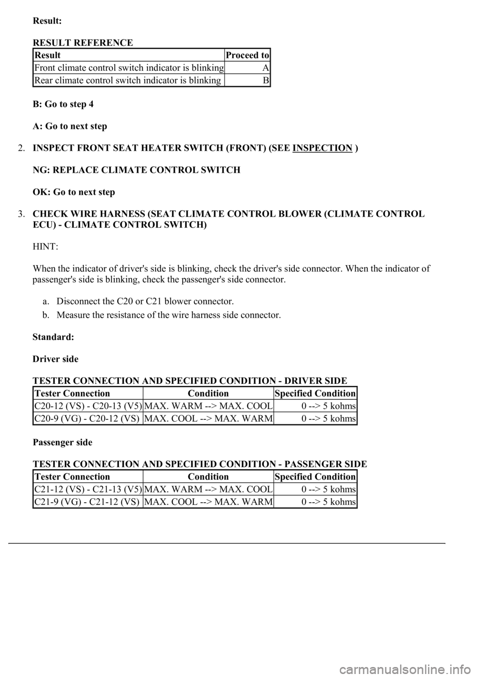
Result:
RESULT REFERENCE
B: Go to step 4
A: Go to next step
2.INSPECT FRONT SEAT HEATER SWITCH (FRONT) (SEE INSPECTION
)
NG: REPLACE CLIMATE CONTROL SWITCH
OK: Go to next step
3.CHECK WIRE HARNESS (SEAT CLIMATE CONTROL BLOWER (CLIMATE CONTROL
ECU) - CLIMATE CONTROL SWITCH)
HINT:
When the indicator of driver's side is blinking, check the driver's side connector. When the indicator of
passenger's side is blinking, check the passenger's side connector.
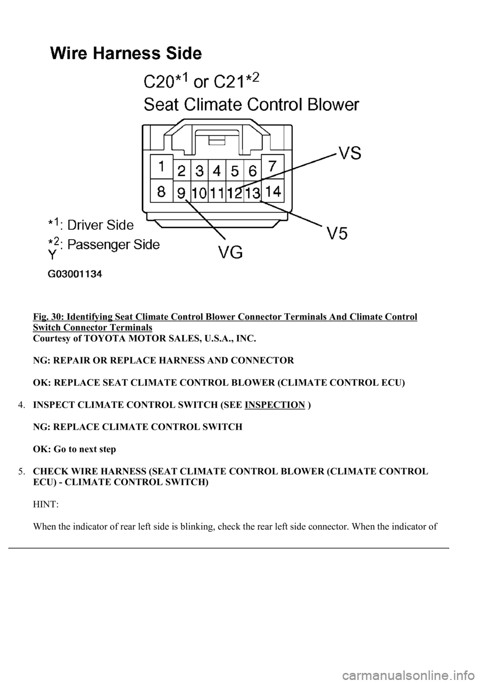
a. Disconnect the C20 or C21 blower connector.
b. Measure the resistance of the wire harness side connector.
Standard:
Driver side
TESTER CONNECTION AND SPECIFIED CONDITION - DRIVER SIDE
Passenger side
TESTER CONNECTION AND SPECIFIED CONDITION - PASSENGER SIDE
ResultProceed to
Front climate control switch indicator is blinkingA
Rear climate control switch indicator is blinkingB
Tester ConnectionConditionSpecified Condition
C20-12 (VS) - C20-13 (V5)MAX. WARM --> MAX. COOL0 --> 5 kohms
C20-9 (VG) - C20-12 (VS)MAX. COOL --> MAX. WARM0 --> 5 kohms
Tester ConnectionConditionSpecified Condition
C21-12 (VS) - C21-13 (V5)MAX. WARM --> MAX. COOL0 --> 5 kohms
C21-9 (VG) - C21-12 (VS)MAX. COOL --> MAX. WARM0 --> 5 kohms
Page 1632 of 4500
Fig. 30: Identifying Seat Climate Control Blower Connector Terminals And Climate Control
Switch Connector Terminals
Courtesy of TOYOTA MOTOR SALES, U.S.A., INC.
NG: REPAIR OR REPLACE HARNESS AND CONNECTOR
OK: REPLACE SEAT CLIMATE CONTROL BLOWER (CLIMATE CONTROL ECU)
4.INSPECT CLIMATE CONTROL SWITCH (SEE INSPECTION
)
NG: REPLACE CLIMATE CONTROL SWITCH
OK: Go to next step
5.CHECK WIRE HARNESS (SEAT CLIMATE CONTROL BLOWER (CLIMATE CONTROL
ECU) - CLIMATE CONTROL SWITCH)
HINT:
When the indicator of rear left side is blinking, check the rear left side connector. When the indicator of
Page 1633 of 4500
rear right side is blinking, check the rear right side connector.
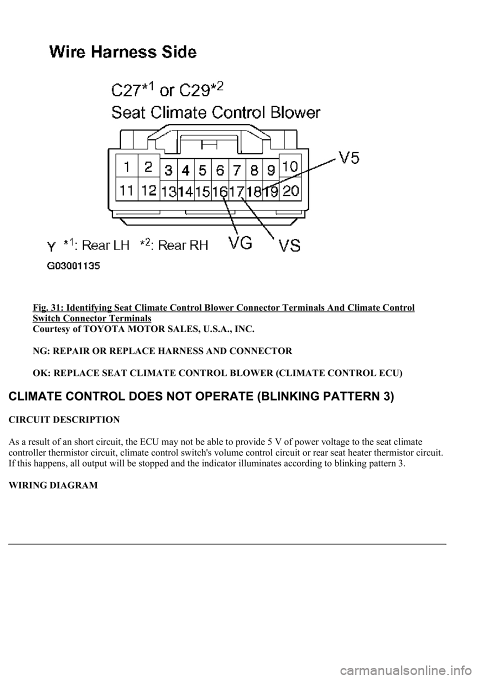
a. Disconnect the C27 or C29 blower connector.
b. Measure the resistance of the wire harness side connector.
Standard:
Rear LH
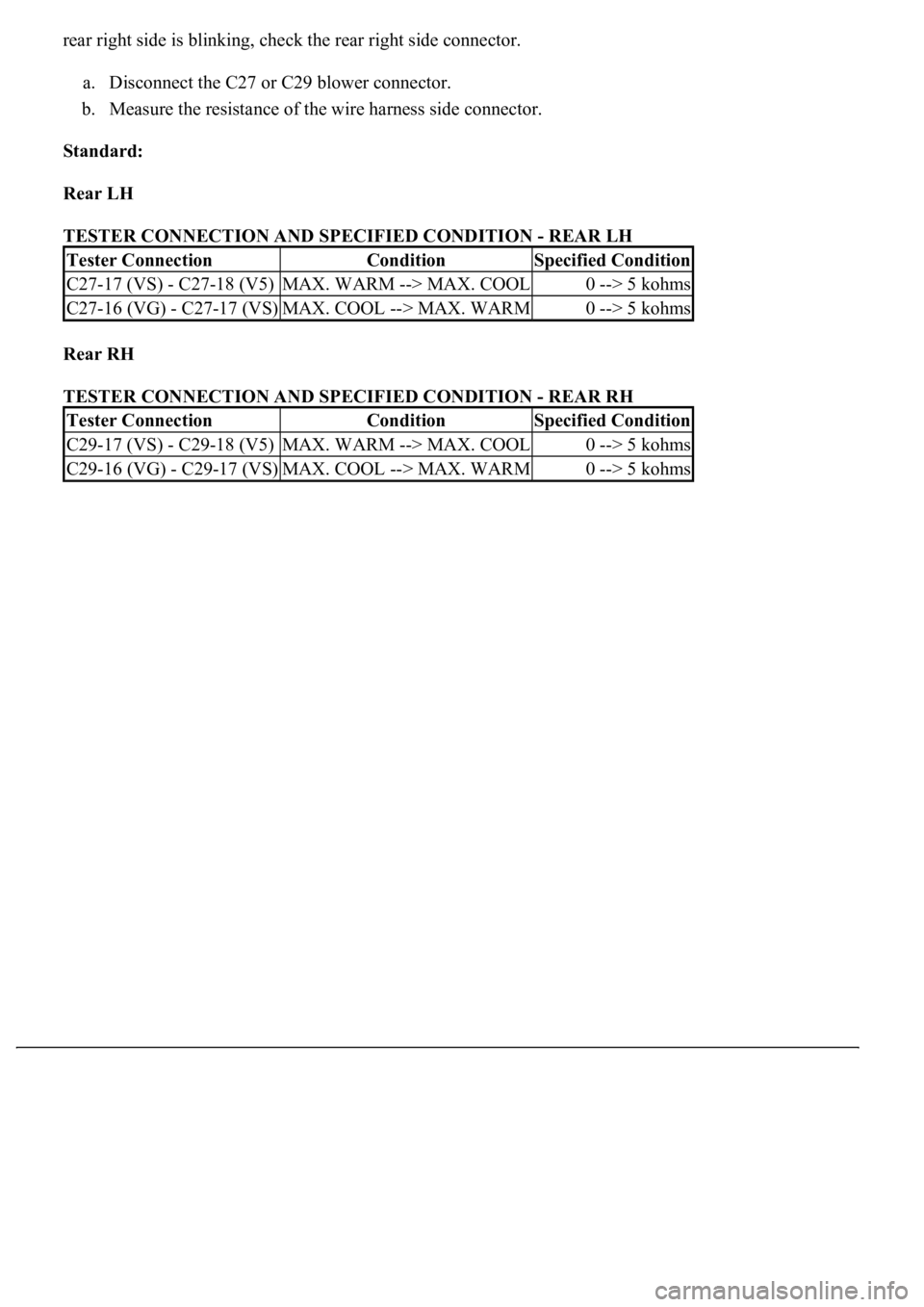
TESTER CONNECTION AND SPECIFIED CONDITION - REAR LH
Rear RH
TESTER CONNECTION AND SPECIFIED CONDITION - REAR RH
Tester ConnectionConditionSpecified Condition
C27-17 (VS) - C27-18 (V5)MAX. WARM --> MAX. COOL0 --> 5 kohms
C27-16 (VG) - C27-17 (VS)MAX. COOL --> MAX. WARM0 --> 5 kohms
Tester ConnectionConditionSpecified Condition
C29-17 (VS) - C29-18 (V5)MAX. WARM --> MAX. COOL0 --> 5 kohms
C29-16 (VG) - C29-17 (VS)MAX. COOL --> MAX. WARM0 --> 5 kohms
Page 1634 of 4500
Fig. 31: Identifying Seat Climate Control Blower Connector Terminals And Climate Control
Switch Connector Terminals
Courtesy of TOYOTA MOTOR SALES, U.S.A., INC.
NG: REPAIR OR REPLACE HARNESS AND CONNECTOR
OK: REPLACE SEAT CLIMATE CONTROL BLOWER (CLIMATE CONTROL ECU)
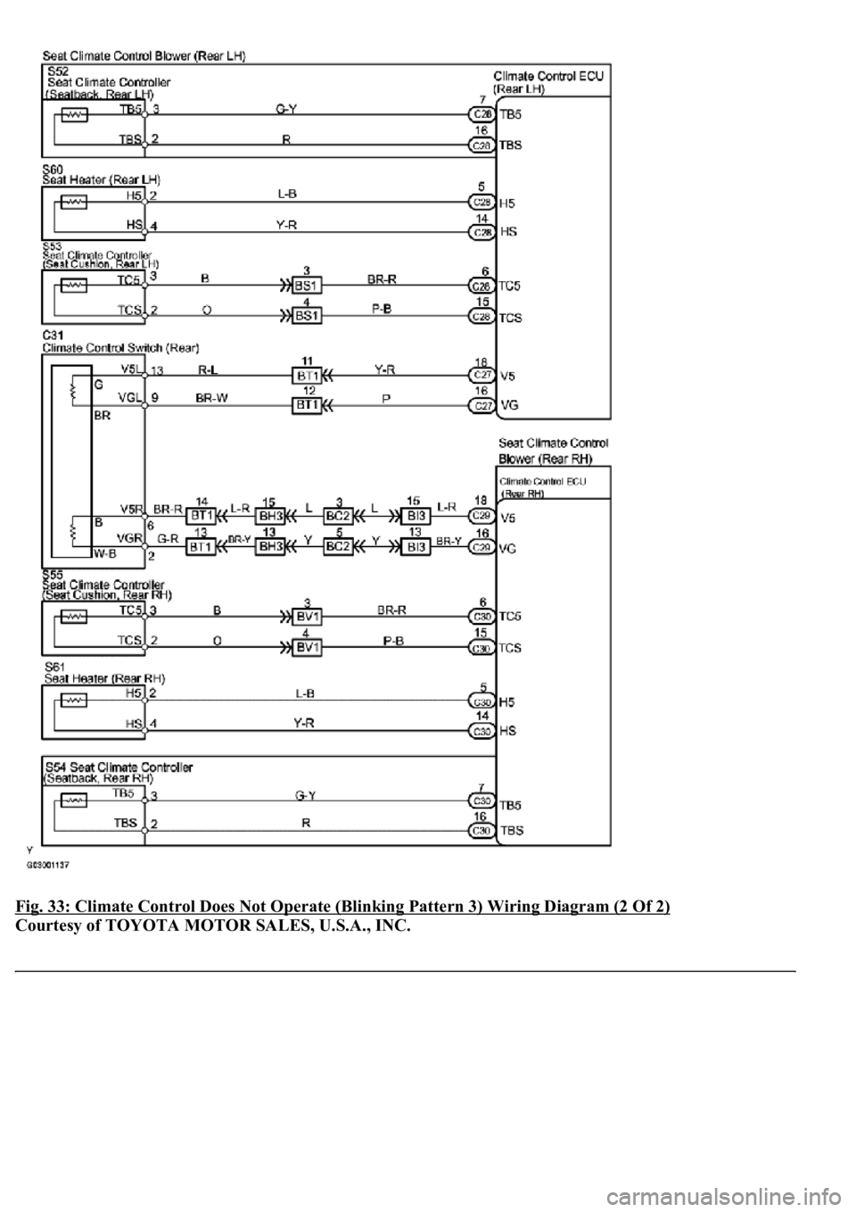
CIRCUIT DESCRIPTION
As a result of an short circuit, the ECU may not be able to provide 5 V of power voltage to the seat climate
controller thermistor circuit, climate control switch's volume control circuit or rear seat heater thermistor circuit.
If this happens, all output will be stopped and the indicator illuminates according to blinking pattern 3.
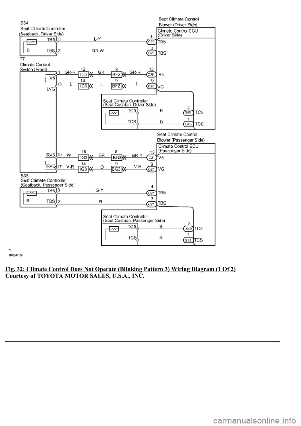
WIRING DIAGRAM
Page 1635 of 4500
Fig. 32: Climate Control Does Not Operate (Blinking Pattern 3) Wiring Diagram (1 Of 2)
Courtesy of TOYOTA MOTOR SALES, U.S.A., INC.
Page 1636 of 4500
Fig. 33: Climate Control Does Not Operate (Blinking Pattern 3) Wiring Diagram (2 Of 2)
Courtesy of TOYOTA MOTOR SALES, U.S.A., INC.
Page 1637 of 4500
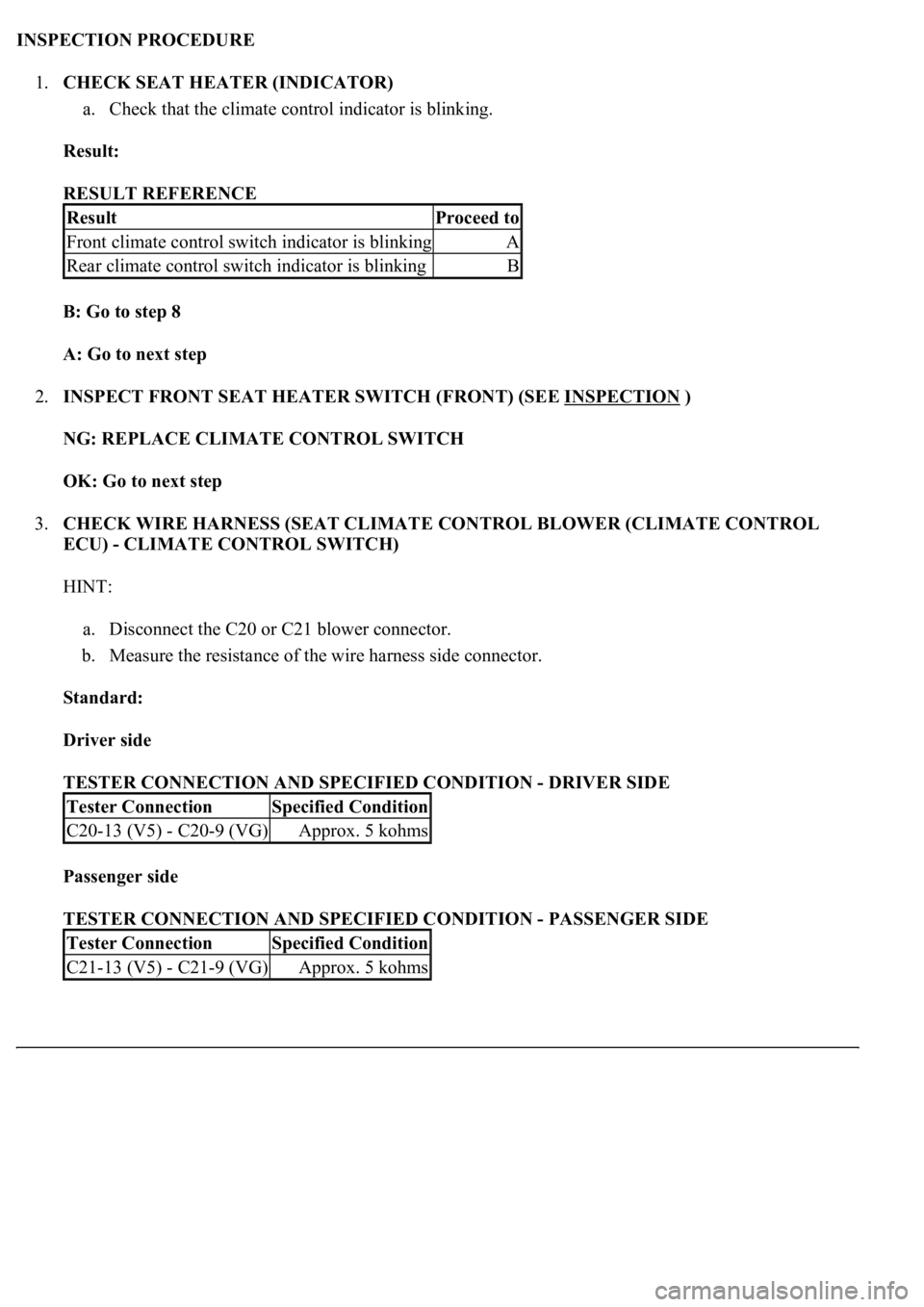
INSPECTION PROCEDURE
1.CHECK SEAT HEATER (INDICATOR)
a. Check that the climate control indicator is blinking.
Result:
RESULT REFERENCE
B: Go to step 8
A: Go to next step
2.INSPECT FRONT SEAT HEATER SWITCH (FRONT) (SEE INSPECTION
)
NG: REPLACE CLIMATE CONTROL SWITCH
OK: Go to next step
3.CHECK WIRE HARNESS (SEAT CLIMATE CONTROL BLOWER (CLIMATE CONTROL
ECU) - CLIMATE CONTROL SWITCH)
HINT:
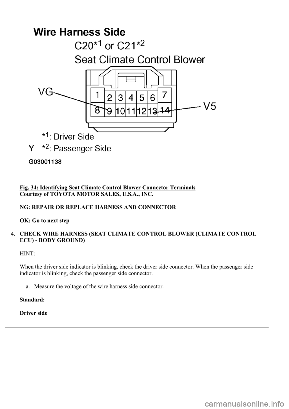
a. Disconnect the C20 or C21 blower connector.
b. Measure the resistance of the wire harness side connector.
Standard:
Driver side
TESTER CONNECTION AND SPECIFIED CONDITION - DRIVER SIDE
Passenger side
TESTER CONNECTION AND SPECIFIED CONDITION - PASSENGER SIDE
ResultProceed to
Front climate control switch indicator is blinkingA
Rear climate control switch indicator is blinkingB
Tester ConnectionSpecified Condition
C20-13 (V5) - C20-9 (VG)Approx. 5 kohms
Tester ConnectionSpecified Condition
C21-13 (V5) - C21-9 (VG)Approx. 5 kohms
Page 1638 of 4500
Fig. 34: Identifying Seat Climate Control Blower Connector Terminals
Courtesy of TOYOTA MOTOR SALES, U.S.A., INC.
NG: REPAIR OR REPLACE HARNESS AND CONNECTOR
OK: Go to next step
4.CHECK WIRE HARNESS (SEAT CLIMATE CONTROL BLOWER (CLIMATE CONTROL
ECU) - BODY GROUND)
HINT:
When the driver side indicator is blinking, check the driver side connector. When the passenger side
indicator is blinking, check the passenger side connector.
a. Measure the voltage of the wire harness side connector.
Standard:
Driver side
Page 1639 of 4500
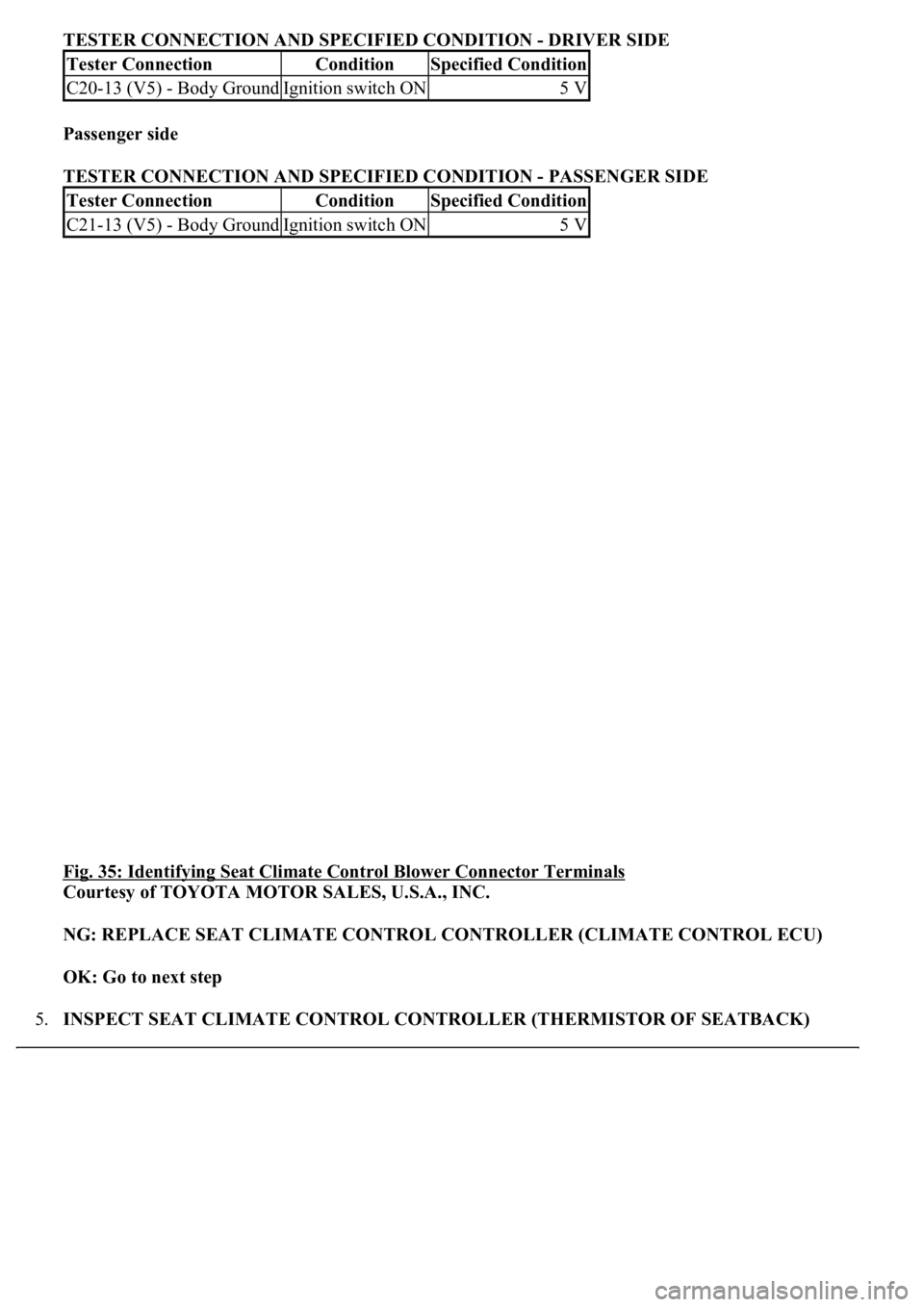
TESTER CONNECTION AND SPECIFIED CONDITION - DRIVER SIDE
Passenger side
TESTER CONNECTION AND SPECIFIED CONDITION - PASSENGER SIDE
Fig. 35: Identifying Seat Climate Control Blower Connector Terminals
Courtesy of TOYOTA MOTOR SALES, U.S.A., INC.
NG: REPLACE SEAT CLIMATE CONTROL CONTROLLER (CLIMATE CONTROL ECU)
OK: Go to next step
5.INSPECT SEAT CLIMATE CONTROL CONTROLLER (THERMISTOR OF SEATBACK)
Tester ConnectionConditionSpecified Condition
C20-13 (V5) - Body GroundIgnition switch ON5 V
Tester ConnectionConditionSpecified Condition
C21-13 (V5) - Body GroundIgnition switch ON5 V
Page 1640 of 4500
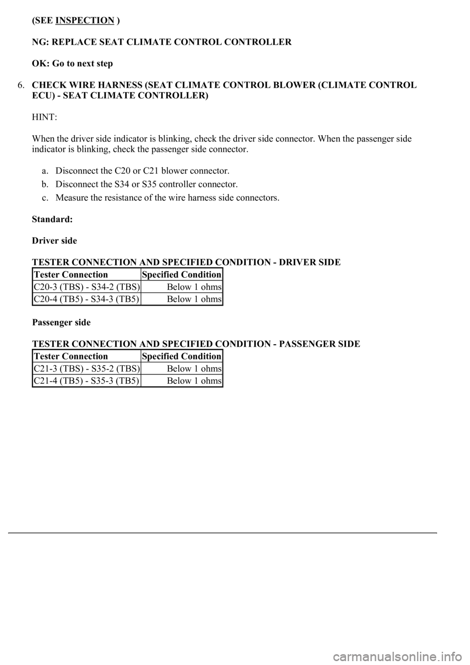
(SEE INSPECTION )
NG: REPLACE SEAT CLIMATE CONTROL CONTROLLER
OK: Go to next step
6.CHECK WIRE HARNESS (SEAT CLIMATE CONTROL BLOWER (CLIMATE CONTROL
ECU) - SEAT CLIMATE CONTROLLER)
HINT:
When the driver side indicator is blinking, check the driver side connector. When the passenger side
indicator is blinking, check the passenger side connector.
a. Disconnect the C20 or C21 blower connector.
b. Disconnect the S34 or S35 controller connector.
c. Measure the resistance of the wire harness side connectors.
Standard:
Driver side
TESTER CONNECTION AND SPECIFIED CONDITION - DRIVER SIDE
Passenger side
TESTER CONNECTION AND SPECIFIED CONDITION - PASSENGER SIDE
Tester ConnectionSpecified Condition
C20-3 (TBS) - S34-2 (TBS)Below 1 ohms
C20-4 (TB5) - S34-3 (TB5)Below 1 ohms
Tester ConnectionSpecified Condition
C21-3 (TBS) - S35-2 (TBS)Below 1 ohms
C21-4 (TB5) - S35-3 (TB5)Below 1 ohms
Trending: service reset, STARTER, wheel, sport mode, air filter, checking oil, Identifying ac

