LEXUS LS430 2003 Factory Repair Manual
Manufacturer: LEXUS, Model Year: 2003, Model line: LS430, Model: LEXUS LS430 2003Pages: 4500, PDF Size: 87.45 MB
Page 231 of 4500

IG - GND (A11-9
- A11-1)LG-R -
W-BPower source (IG)Ignition switch OFF.0 V
TSDr - GND
(A11-19 - A11-1)L - W-BSolar sensor signal (Driver
side)Ignition switch ON. Solar sensor
subjected to electric light.0.8 to 4.3 V
TSDr - GND
(A11-19 - A11-1)L - W-BSolar sensor signal (Driver
side)Ignition switch ON. Solar sensor
covered by a cloth.Below 0.8 V
TSPa - GND
(A11-20 - A11-1)G-R - W-
BSolar sensor signal
(Passenger side)Ignition switch ON. Solar sensor
subjected to electric light.0.8 to 4.3 V
TSPa - GND
(A11-20 - A11-1)G-R - W-
BSolar sensor signal
(Passenger side)Ignition switch ON. Solar sensor
covered by a cloth.Below 0.8 V
+B - GND (A11-
21 - A11-1)B-Y - W-
BPower source (Back-up)Always10 to 14 V
DGS - SG-1
(A11-29 - A13-8)B - YExhaust gas sensor signal
After 30 seconds from Ignition
switch ON and the sensor is
exposed to the exhaust gas.
1.0 to 4.5 V
DS1 - GND
(A12-1 - A11-1)V - W-BSwing grill STEP motor
signal
Ignition switch ON. Blower
motor: Operating Mode selector:
BI-LEVEL Intelligent swing
register: ON
Pulse
generation
Symbols
(Terminal No.)Wiring
colorTerminal DescriptionConditionSpecification
DS2 - GND
(A12-2 - A11-1)G - W-BSwing grill STEP motor
signal
Ignition switch ON. Blower
motor: Operating Mode selector:
BI-LEVEL Intelligent swing
register: ON
Pulse
generation
PS1 - GND (A12-
3 - A11-1)R-B - W-
BSwing grill STEP motor
signal
Ignition switch ON. Blower
motor: Operating Mode selector:
BI-LEVEL Intelligent swing
register: ON
Pulse
generation
PS2 - GND (A12-
4 - A11-1)B - W-BSwing grill STEP motor
signal
Ignition switch ON. Blower
motor: Operating Mode selector:
BI-LEVEL Intelligent swing
register: ON
Pulse
generation
PS3 - GND (A12-
5 - A11-1)P - W-BSwing grill STEP motor
signal
Ignition switch ON. Blower
motor: Operating Mode selector:
BI-LEVEL Intelligent swing
register: ON
Pulse
generation
PS4 - GND (A12-
6 - A11-1)Y-R - W-
BSwing grill STEP motor
signal
Ignition switch ON. Blower
motor: Operating Mode selector:
BI-LEVEL Intelligent swing
register: ON
Pulse
generation
DUAL - DrGND
(A12-7 - A12-11)O - LG-RDual temperature control
signalIgnition switch ON. Dual switch
ON.Below 1.0 V
DUAL - DrGND
(A12-7 - A12-11)O - LG-RDual temperature control
signalIgnition switch ON. Dual switch
OFF.10 to 14 V
Page 232 of 4500

DS3 - GND
(A12-8 - A11-1)B-R - W-
BSwing grill STEP motor
signal
Ignition switch ON. Blower
motor: Operating Mode selector:
BI-LEVEL Intelligent swing
register: ON
Pulse
generation
DS4 - GND
(A12-9 - A11-1)G-B - W-
BSwing grill STEP motor
signal
Ignition switch ON. Blower
motor: Operating Mode selector:
BI-LEVEL Intelligent swing
register: ON
Pulse
generation
DUIND+ -
DUIND - (A12-
10 - A12-13)G-R - B-
WDriver temperature and
passenger temperature
communication signalDriver temperature and passenger
temperature are different.5 to 14 V
DUIND+ -
DUIND- (A12-10
- A12-13)G-R - B-
WDriver temperature and
passenger temperature
communication signalDriver temperature and passenger
temperature are the same.Below 1.0 V
S5-2 - SG-5
(A12-15 - A13-
12)
V-R - LGPressure sensor operation
voltageIgnition switch ON.4.5 to 5.5 V
S5-4 - TSRr(2)
(A12-16 - A11-
30)
GR - W-LRear solar sensor signalIgnition switch ON. Rear solar
sensor subjected to electric light.0.8 to 4.3 V
S5-4 - TSRr(2)
(A12-16 - A11-
30)
GR - W-LRear solar sensor signalIgnition switch ON. Rear solar
sensor covered by a cloth.Below 1.0 V
PRS - SG-5
(A12-17 - A13-
12)
V - LGPressure sensor signalRefrigerant pressure 0 Mpa (0
kgf.cm, 0 psi).0.5V
PRS - SG-5
(A12-17 - A13-
12)
V - LGPressure sensor signalRefrigerant pressure 2.9 Mpa (30
kgf.cm, 427 psi).4.5 V
TAMOUT - GND
(1) (A12-18 -
A11-1)L - W-BVehicle speed signalIgnition switch ON.Pulse
generation
PaDN - PaGND
(A12-19 - A12-
12)R-W - Y-
RTemperature control
switch signal (Passenger
side)Push passenger temperature
switch OFF.10 to 14 V
PaDN - PaGND
(A12-19 - A12-
12)R-W - Y-
RTemperature control
switch signal (Passenger
side)Push passenger temperature
switch ON.Below 1.0 V
PaUP - PaGND
(A12-20 - A12-
12)
W - Y-R
Temperature control
switch signal (Passenger
side)Push passenger temperature
switch OFF.10 to 14 V
Symbols
(Terminal No.)Wiring
colorTerminal DescriptionConditionSpecification
PaUP - PaGND
(A12-20 - A12-W - Y-RTemperature control
switch signal (Passenger
Push passenger temperature Below 1.0 V
Page 233 of 4500

12)side)switch ON.
DrDN - DrGND
(A12-21 - A12-
11)P-L - LG-
RTemperature control
switch signal (Driver side)Push driver temperature switch
OFF.10 to 14 V
DrDN - DrGND
(A12-21 - A12-
11)P-L - LG-
RTemperature control
switch signal (Driver side)Push driver temperature switch
ON.Below 1.0 V
DrUP - DrGND
(A12-22 - A12-
11)V-W -
LG-RTemperature control
switch signal (Driver side)Push driver temperature switch
OFF.10 to 14 V
DrUP - DrGND
(A12-22 - A12-
11)V-W -
LG-RTemperature control
switch signal (Driver side)Push driver temperature switch
ON.Below 1.0 V
PS+B - GND
(A12-24 - A11-1)R-G - W-
BSwing grill STEP motor
operation voltageAlways10 to 14 V
TFACEPa - SG-4
(A13-14 - A13-
11)B-Y - Y-
GDuct sensor signal
(Passenger side)Ignition switch ON. Passenger
side duct sensor temperature 25 °
C (77 °F).
1.8 to 2.2 V
TFACEPa - SG-4
(A13-14 - A13-
11)B-Y - Y-
GDuct sensor signal
(Passenger side)Ignition switch ON. Passenger
side duct sensor temperature 50 °
C (122 °F).
0.8 to 1.2 V
TFACEDr - SG-3
(A13-15 - A13-
10)GR-R -
R-WDuct sensor signal (Driver
side)Ignition switch ON. Passenger
side duct sensor temperature 25 °
C (77 °F).
1.8 to 2.2 V
TFACEDr - SG-3
(A13-15 - A13-
10)GR-R -
R-WDuct sensor signal (Driver
side)Ignition switch ON. Passenger
side duct sensor temperature 50 °
C (122 °F).
0.8 to 1.2 V
TR - SG-2 (A13-
16 - A13-9)W-L - Y-
BRoom temperature sensor
signalIgnition switch ON. Room
temperature 25 °C (77°F).1.8 to 2.2 V
TR - SG-2 (A13-
16 - A13-9)W-L - Y-
BRoom temperature sensor
signalIgnition switch ON. Room
temperature 40 °C (104°F).0.8 to 1.2 V
NOX - Body
ground (A13-17 -
Body ground)L-B -
Body
ground
Exhaust gas sensor signal
After 120 seconds from Ignition
switch ON and the sensor is
exposed to the exhaust gas.
1.0 to 4.5 V
AMDr1 - GND
(A37-1 - A11-1)BR - W-B
Air mix servomotor
operation signal (Driver
side)During actuator check mode.
Change display code 0 to display
code 9.Pulse
generation
AMDr2 - GND
(A37-2 - A11-1)BR-B -
W-BAir mix servomotor
operation signal (Driver
side)During actuator check mode.
Change display code 0 to display
code 9.Pulse
generation
AMDr3 - GND
(A37-3 - A11-1)BR-W -
W-BAir mix servomotor
operation signal (Driver
side)During actuator check mode.
Change display code 0 to display
code 9.Pulse
generation
AMDr4 - GND
(A37-4 - A11-1)BR-Y -
W-BAir mix servomotor
operation signal (Driver During actuator check mode.
Change display code 0 to display Pulse
generation
Page 234 of 4500

side)code 9.
AODr1 - GND
(A37-5 - A11-1)L - W-B
Air outlet servomotor
operation signal (Driver
side)During actuator check mode.
Change display code 0 to display
code 9.Pulse
generation
AODr2 - GND
(A37-6 - A11-1)L-B - W-
BAir outlet servomotor
operation signal (Driver
side)During actuator check mode.
Change display code 0 to display
code 9.Pulse
generation
WVS - GND
(A37-7 - A11-1)G-W - W-
BWater valve servomotor
operation signalIgnition switch ON. Set
temperature control to MAX.
COOL
Below 1.0 V
WVS - GND
(A37-7 - A11-1)G-W - W-
BWater valve servomotor
operation signalIgnition switch ON. Set
temperature control to MAX.
HOT
10 to 14 V
ABOPa - GND
(A37-8 - A11-1)G-B - W-
BCool air bypass
servomotor operation
signal (Passenger side)During actuator check mode.
Display code 0.10 to 14 V
ABOPa - GND
(A37-8 - A11-1)G-B - W-
BCool air bypass
servomotor operation
signal (Passenger side)
Display code 9.Below 1.0 V
Symbols
(Terminal No.)Wiring
colorTerminal DescriptionConditionSpecification
ABSPa - GND
(A37-9 - A11-1)G-O - W-
BCool air bypass
servomotor operation
signal (Passenger side)During actuator check mode.
Display code 0.Below 1.0 V
ABSPa - GND
(A37-9 - A11-1)G-O - W-
BCool air bypass
servomotor operation
signal (Passenger side)
Display code 9.10 to 14 V
AMDB - GND
(A37-10 - A11-1)R-B - W-
BAir mix servomotor
operation voltage (Driver
side)
Always10 to 14 V
AODr3 - GND
(A37-12 - A11-1)L-W - W-
BAir outlet servomotor
operation signal (Driver
side)During actuator check mode.
Change display code 0 to display
code 9.Pulse
generation
AODr4 - GND
(A37-13 - A11-1)L-R - W-
BAir outlet servomotor
operation signal (Driver
side)During actuator check mode.
Change display code 0 to display
code 9.Pulse
generation
WVIG - GND
(A37-14 - A11-1)O - W-BWater valve servomotor
operation voltageIgnition switch ON.10 to 14 V
WVIG - GND
(A37-14 - A11-1)O - W-BWater valve servomotor
operation voltageIgnition switch OFF.0 V
WVO - GND
(A37-15 - A11-1)G - W-BWater valve servomotor
operation signalIgnition switch ON. Set
temperature control to MAX.
COOL.
10 to 14 V
WVO - GND
(A37-15 - A11-1)G - W-BWater valve servomotor
operation signalIgnition switch ON. Set
temperature control to MAX. Below 1.0 V
Page 235 of 4500

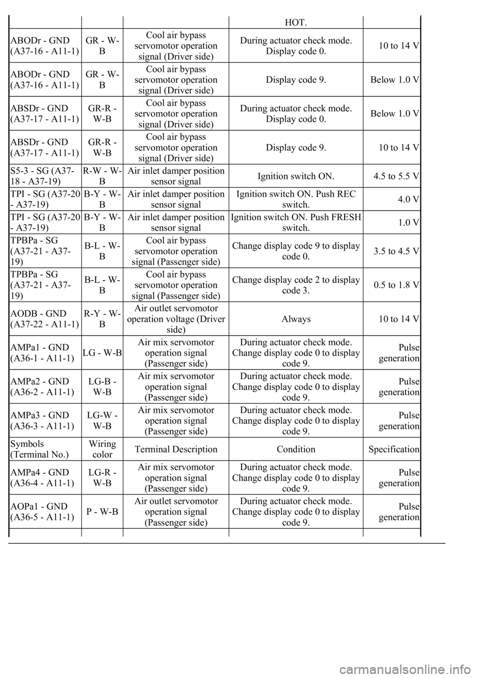
HOT.
ABODr - GND
(A37-16 - A11-1)GR - W-
BCool air bypass
servomotor operation
signal (Driver side)During actuator check mode.
Display code 0.10 to 14 V
ABODr - GND
(A37-16 - A11-1)GR - W-
BCool air bypass
servomotor operation
signal (Driver side)
Display code 9.Below 1.0 V
ABSDr - GND
(A37-17 - A11-1)GR-R -
W-BCool air bypass
servomotor operation
signal (Driver side)During actuator check mode.
Display code 0.Below 1.0 V
ABSDr - GND
(A37-17 - A11-1)GR-R -
W-BCool air bypass
servomotor operation
signal (Driver side)
Display code 9.10 to 14 V
S5-3 - SG (A37-
18 - A37-19)R-W - W-
BAir inlet damper position
sensor signalIgnition switch ON.4.5 to 5.5 V
TPI - SG (A37-20
- A37-19)B-Y - W-
BAir inlet damper position
sensor signalIgnition switch ON. Push REC
switch.4.0 V
TPI - SG (A37-20
- A37-19)B-Y - W-
BAir inlet damper position
sensor signalIgnition switch ON. Push FRESH
switch.1.0 V
TPBPa - SG
(A37-21 - A37-
19)B-L - W-
BCool air bypass
servomotor operation
signal (Passenger side)Change display code 9 to display
code 0.3.5 to 4.5 V
TPBPa - SG
(A37-21 - A37-
19)B-L - W-
BCool air bypass
servomotor operation
signal (Passenger side)Change display code 2 to display
code 3.0.5 to 1.8 V
AODB - GND
(A37-22 - A11-1)R-Y - W-
BAir outlet servomotor
operation voltage (Driver
side)
Always10 to 14 V
AMPa1 - GND
(A36-1 - A11-1)LG - W-B
Air mix servomotor
operation signal
(Passenger side)During actuator check mode.
Change display code 0 to display
code 9.Pulse
generation
AMPa2 - GND
(A36-2 - A11-1)LG-B -
W-BAir mix servomotor
operation signal
(Passenger side)During actuator check mode.
Change display code 0 to display
code 9.Pulse
generation
AMPa3 - GND
(A36-3 - A11-1)LG-W -
W-BAir mix servomotor
operation signal
(Passenger side)During actuator check mode.
Change display code 0 to display
code 9.Pulse
generation
Symbols
(Terminal No.)Wiring
colorTerminal DescriptionConditionSpecification
AMPa4 - GND
(A36-4 - A11-1)LG-R -
W-BAir mix servomotor
operation signal
(Passenger side)During actuator check mode.
Change display code 0 to display
code 9.Pulse
generation
AOPa1 - GND
(A36-5 - A11-1)P - W-B
Air outlet servomotor
operation signal
(Passenger side)During actuator check mode.
Change display code 0 to display
code 9.Pulse
generation
Page 236 of 4500

AOPa2 - GND
(A36-6 - A11-1)P-B - W-
BAir outlet servomotor
operation signal
(Passenger side)During actuator check mode.
Change display code 0 to display
code 9.Pulse
generation
AOPa3 - GND
(A36-7 - A11-1)P-G - W-
BAir outlet servomotor
operation signal
(Passenger side)During actuator check mode.
Change display code 0 to display
code 9.Pulse
generation
AOPa4 - GND
(A36-9 - A11-1)P-L - W-
BAir outlet servomotor
operation signal
(Passenger side)During actuator check mode.
Change display code 0 to display
code 9.Pulse
generation
S5-5 - SG-7(1)
(A36-11 - A36-
15)
R - W-L
Cool air bypass damper
position sensor signal
(Driver side)
Ignition switch ON.4.5 to 5.5 V
S5-5 - SG-7(2)
(A36-11 - A36-
15)
R - W-L
Cool air bypass damper
position sensor signal
(Passenger side)
Ignition switch ON.4.5 to 5.5 V
AMPB - GND
(A36-13 - A11-1)Y - W-B
Air mix servomotor
operation voltage
(Passenger side)
Always10 to 14 V
AIF - SG (A36-
16 - A37-19)G-R - W-
BAir inlet damper position
sensor signalIgnition switch ON. Push REC
switch.Below 1.0 V
AIF - SG (A36-
16 - A37-19)G-R - W-
BAir inlet damper position
sensor signalIgnition switch ON. Push FRESH
switch.10 to 14 V
AIR - SG (A36-
17 - A37-19)G-Y - W-
BAir inlet damper position
sensor signalIgnition switch ON. Push FRESH
switch.Below 1.0 V
AIR - SG (A36-
17 - A37-19)G-Y - W-
BAir inlet damper position
sensor signalIgnition switch ON. Push REC
switch.10 to 14 V
TE - SG-7 (A36-
20 - A36-15)L-Y - W-
LEvaporator temperature
sensor signalIgnition switch ON. Evaporator
temperature 0 °C (32 °F).2.0 to 2.4V
TE - SG-7 (A36-
20 - A36-15)L-Y - W-
LEvaporator temperature
sensor signalIgnition switch ON. Evaporator
temperature 15 °C (59 °F).1.4 to 1.8 V
TPBDr - SG-7
(A36-24 - A36-
15)B-R - W-
LCool air bypass
servomotor operation
signal (Driver side)Change display code 9 to display
code 0.3.5 to 4.5 V
TPBDr - SG-7
(A36-24 - A36-
15)B-R - W-
LCool air bypass
servomotor operation
signal (Driver side)Change display code 2 to display
code 3.0.5 to 1.8 V
AOPB - GND
(A36-26 - A11-1)Y-R - W-
BAir outlet servomotor
operation voltage
(Passenger side)
Always10 to 14 V
(1)w/o LEXUS Navigation System
(2)w/ Rear A/C
Page 237 of 4500

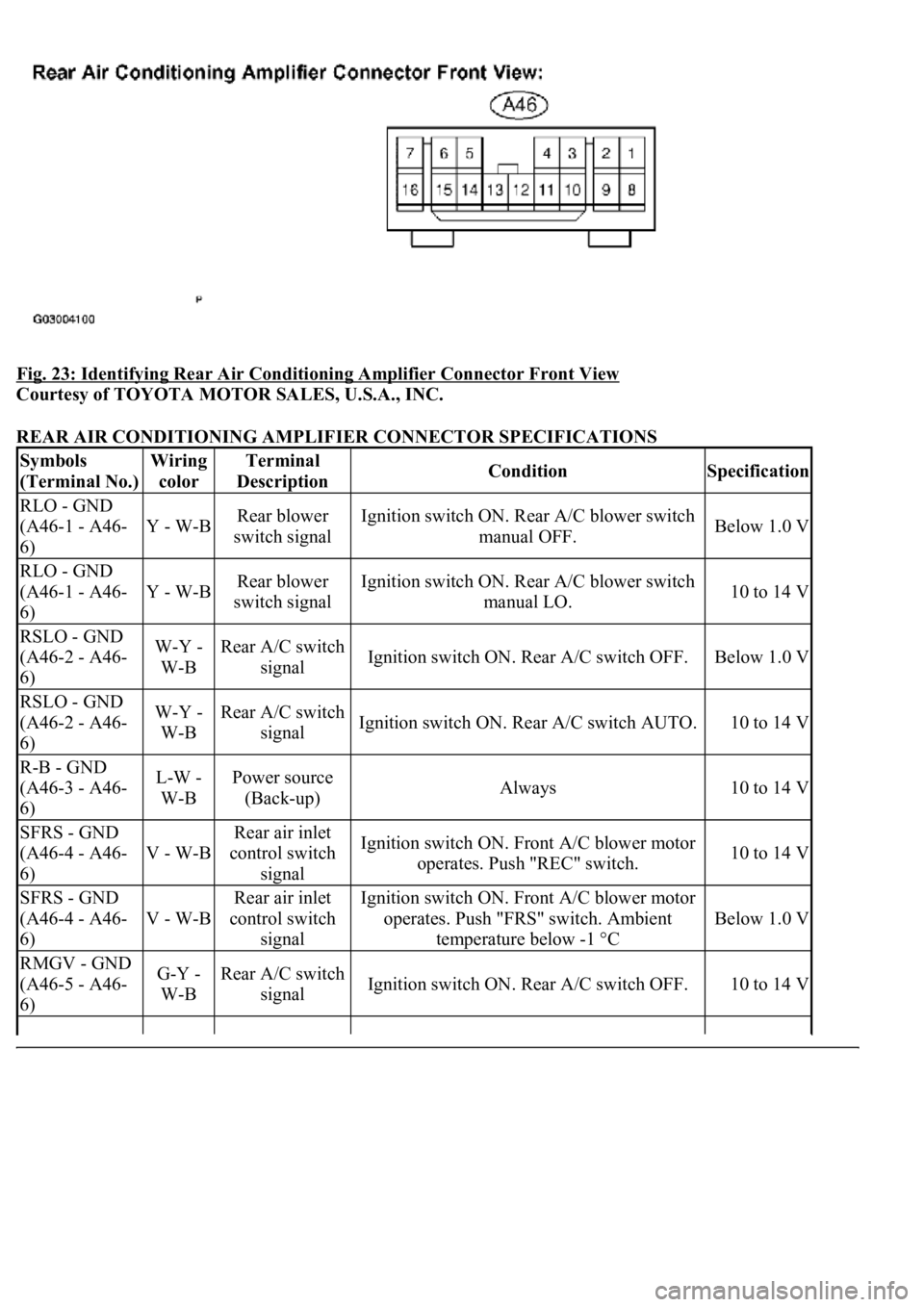
Fig. 23: Identifying Rear Air Conditioning Amplifier Connector Front View
Courtesy of TOYOTA MOTOR SALES, U.S.A., INC.
REAR AIR CONDITIONING AMPLIFIER CONNECTOR SPECIFICATIONS
Symbols
(Terminal No.)Wiring
colorTerminal
DescriptionConditionSpecification
RLO - GND
(A46-1 - A46-
6)
Y - W-BRear blower
switch signalIgnition switch ON. Rear A/C blower switch
manual OFF.Below 1.0 V
RLO - GND
(A46-1 - A46-
6)
Y - W-BRear blower
switch signalIgnition switch ON. Rear A/C blower switch
manual LO.10 to 14 V
RSLO - GND
(A46-2 - A46-
6)W-Y -
W-BRear A/C switch
signalIgnition switch ON. Rear A/C switch OFF.Below 1.0 V
RSLO - GND
(A46-2 - A46-
6)W-Y -
W-BRear A/C switch
signalIgnition switch ON. Rear A/C switch AUTO.10 to 14 V
R-B - GND
(A46-3 - A46-
6)L-W -
W-BPower source
(Back-up)Always10 to 14 V
SFRS - GND
(A46-4 - A46-
6)
V - W-B
Rear air inlet
control switch
signalIgnition switch ON. Front A/C blower motor
operates. Push "REC" switch.10 to 14 V
SFRS - GND
(A46-4 - A46-
6)
V - W-B
Rear air inlet
control switch
signalIgnition switch ON. Front A/C blower motor
operates. Push "FRS" switch. Ambient
temperature below -1 °C
Below 1.0 V
RMGV - GND
(A46-5 - A46-
6)G-Y -
W-BRear A/C switch
signalIgnition switch ON. Rear A/C switch OFF.10 to 14 V
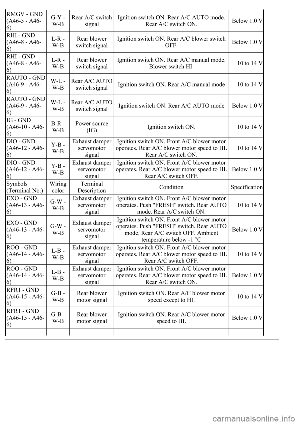
Page 238 of 4500

RMGV - GND
(A46-5 - A46-
6)G-Y -
W-BRear A/C switch
signalIgnition switch ON. Rear A/C AUTO mode.
Rear A/C switch ON.Below 1.0 V
RHI - GND
(A46-8 - A46-
6)L-R -
W-BRear blower
switch signalIgnition switch ON. Rear A/C blower switch
OFF.Below 1.0 V
RHI - GND
(A46-8 - A46-
6)L-R -
W-BRear blower
switch signalIgnition switch ON. Rear A/C manual mode.
Blower switch HI.10 to 14 V
RAUTO - GND
(A46-9 - A46-
6)W-L -
W-BRear A/C AUTO
switch signalIgnition switch ON. Rear A/C manual mode10 to 14 V
RAUTO - GND
(A46-9 - A46-
6)W-L -
W-BRear A/C AUTO
switch signalIgnition switch ON. Rear A/C AUTO modeBelow 1.0 V
IG - GND
(A46-10 - A46-
6)B-R -
W-BPower source
(IG)Ignition switch ON.10 to 14 V
DIO - GND
(A46-12 - A46-
6)Y-B -
W-BExhaust damper
servomotor
signalIgnition switch ON. Front A/C blower motor
operates. Rear A/C blower motor speed to HI.
Rear A/C switch ON.
10 to 14 V
DIO - GND
(A46-12 - A46-
6)Y-B -
W-BExhaust damper
servomotor
signalIgnition switch ON. Front A/C blower motor
operates. Rear A/C blower motor speed to HI.
Rear A/C switch OFF.
Below 1.0 V
Symbols
(Terminal No.)Wiring
colorTerminal
DescriptionConditionSpecification
EXO - GND
(A46-13 - A46-
6)G-W -
W-BExhaust damper
servomotor
signalIgnition switch ON. Front A/C blower motor
operates. Push "FRESH" switch. Rear AUTO
mode. Rear A/C switch ON.
10 to 14 V
EXO - GND
(A46-13 - A46-
6)G-W -
W-BExhaust damper
servomotor
signalIgnition switch ON. Front A/C blower motor
operates. Push "FRESH" switch. Rear AUTO
mode. Rear A/C switch OFF. Ambient
temperature below -1 °C
Below 1.0 V
ROO - GND
(A46-14 - A46-
6)L-B -
W-BExhaust damper
servomotor
signalIgnition switch ON. Front A/C blower motor
operates. Rear A/C blower motor speed to HI.
Rear A/C switch OFF.
10 to 14 V
ROO - GND
(A46-14 - A46-
6)L-B -
W-BExhaust damper
servomotor
signalIgnition switch ON. Front A/C blower motor
operates. Rear A/C blower motor speed to HI.
Rear A/C switch ON.
Below 1.0 V
RFR1 - GND
(A46-15 - A46-
6)G-B -
W-BRear blower
motor signalIgnition switch ON. Rear A/C blower motor
speed except to HI.10 to 14 V
RFR1 - GND
(A46-15 - A46-
6)G-B -
W-BRear blower
motor signalIgnition switch ON. Rear A/C blower motor
speed to HI.Below 1.0 V
Page 239 of 4500

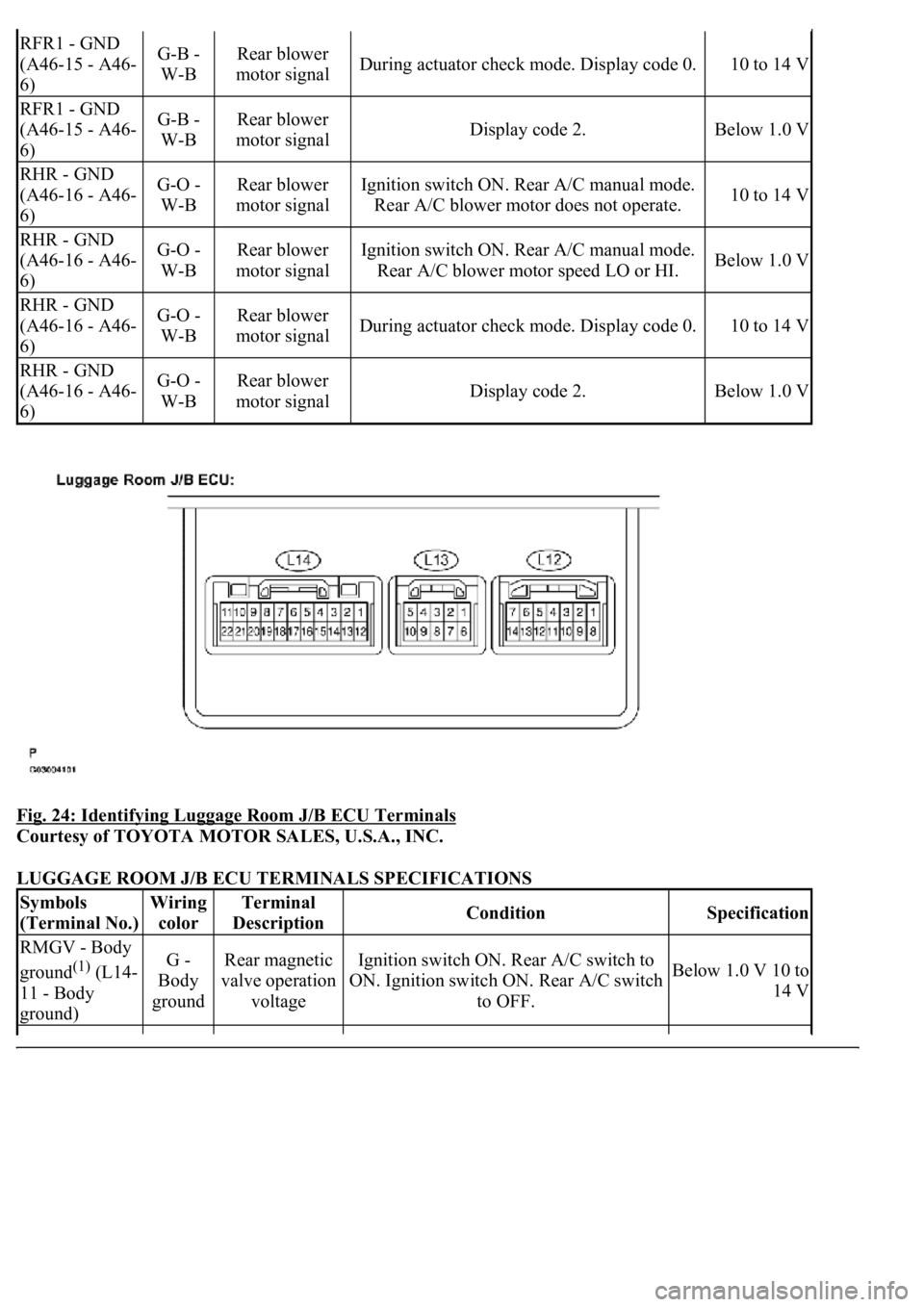
Fig. 24: Identifying Luggage Room J/B ECU Terminals
Courtesy of TOYOTA MOTOR SALES, U.S.A., INC.
LUGGAGE ROOM J/B ECU TERMINALS SPECIFICATIONS
RFR1 - GND
(A46-15 - A46-
6)G-B -
W-BRear blower
motor signalDuring actuator check mode. Display code 0.10 to 14 V
RFR1 - GND
(A46-15 - A46-
6)G-B -
W-BRear blower
motor signalDisplay code 2.Below 1.0 V
RHR - GND
(A46-16 - A46-
6)G-O -
W-BRear blower
motor signalIgnition switch ON. Rear A/C manual mode.
Rear A/C blower motor does not operate.10 to 14 V
RHR - GND
(A46-16 - A46-
6)G-O -
W-BRear blower
motor signalIgnition switch ON. Rear A/C manual mode.
Rear A/C blower motor speed LO or HI.Below 1.0 V
RHR - GND
(A46-16 - A46-
6)G-O -
W-BRear blower
motor signalDuring actuator check mode. Display code 0.10 to 14 V
RHR - GND
(A46-16 - A46-
6)G-O -
W-BRear blower
motor signalDisplay code 2.Below 1.0 V
Symbols
(Terminal No.)Wiring
colorTerminal
DescriptionConditionSpecification
RMGV - Body
ground
(1) (L14-
11 - Body
ground)G -
Body
groundRear magnetic
valve operation
voltageIgnition switch ON. Rear A/C switch to
ON. Ignition switch ON. Rear A/C switch
to OFF.Below 1.0 V 10 to
14 V
Page 240 of 4500

HINT:
The followings are the possible items to be customized.
AIR CONDITIONER
AIR CONDITIONER CUSTOMIZE PARAMETERS
SMOK - Body
ground (L14-16
- Body ground)L - Body
groundSmoke sensor
operation signal
Ignition switch ON. Rear A/C switch to
AUTO. By using cigarette smoke. Ignition
switch ON. Rear A/C switch to AUTO. By
not using cigarette smoke.
Above 4.0 V
Below 1.0 V
AUTO - Body
ground (L14-17
- Body ground)W -
Body
groundAuto switch
signal
Ignition switch ON. Rear A/C rear seat
AUTO indicator lights up. Ignition switch
ON. Rear A/C rear seat AUTO indicator
does not light up.
Below 1.0 V 10 to
14 V
RHR - Body
ground (L14-18
- Body ground)V -
Body
groundRear blower
motor operation
signal
Ignition switch ON. Rear A/C manual
mode. Rear A/C blower motor does not
operate. Ignition switch ON. Rear A/C
manual mode. Rear A/C blower motor
speed LO or HI. During actuator check
mode. Display code 0. Display code 2.
10 to 14 V Below
1.0 V 10 to 14 V
Below 1.0 V
RFR - Body
ground (L14-19
- Body ground)Y -
Body
groundRear blower
motor operation
signal
Ignition switch ON. Rear A/C blower
motor speed to except HI. Ignition switch
ON. Rear A/C blower motor speed to HI.
During actuator check mode. Display code
0. Display code 2.
10 to 14 V Below
1.0 V 10 to 14 V
Below 1.0 V
FRS - Body
ground (L14-20
- Body ground)B -
Body
groundExhaust damper
servomotor
operation signal
Ignition switch ON. Front A/C blower
motor operates. Push "FRS" switch.
Ambient temperature below -1 °C Ignition
switch ON. Front A/C blower motor
operates. Push "REC" switch.
10 to 14 V Below
1.0 V
(1)w/ Rear A/C
DISPLAY (ITEM)DEFAULTCONTENTSSETTING