LEXUS LS430 2003 Factory Repair Manual
Manufacturer: LEXUS, Model Year: 2003,
Model line: LS430,
Model: LEXUS LS430 2003
Pages: 4500, PDF Size: 87.45 MB
LEXUS LS430 2003 Factory Repair Manual
LS430 2003
LEXUS
LEXUS
https://www.carmanualsonline.info/img/36/57050/w960_57050-0.png
LEXUS LS430 2003 Factory Repair Manual
Trending: TPMS, torque, heating, electronic modulated, spark plugs replace, alternator, steering
Page 211 of 4500
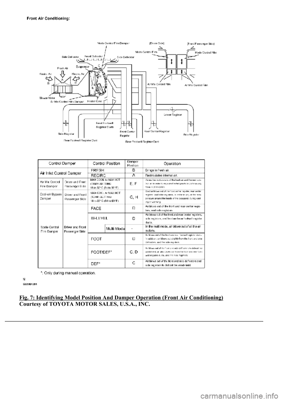
Fig. 7: Identifying Model Position And Damper Operation (Front Air Conditioning)
Courtesy of TOYOTA MOTOR SALES, U.S.A., INC.
Page 212 of 4500
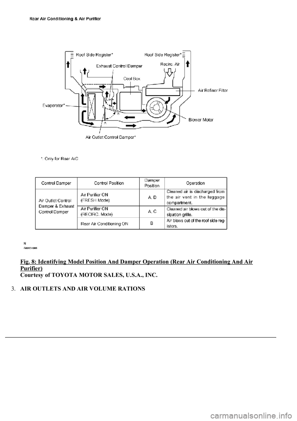
Fig. 8: Identifying Model Position And Damper Operation (Rear Air Conditioning And Air
Purifier)
Courtesy of TOYOTA MOTOR SALES, U.S.A., INC.
3.AIR OUTLETS AND AIR VOLUME RATIONS
Page 213 of 4500
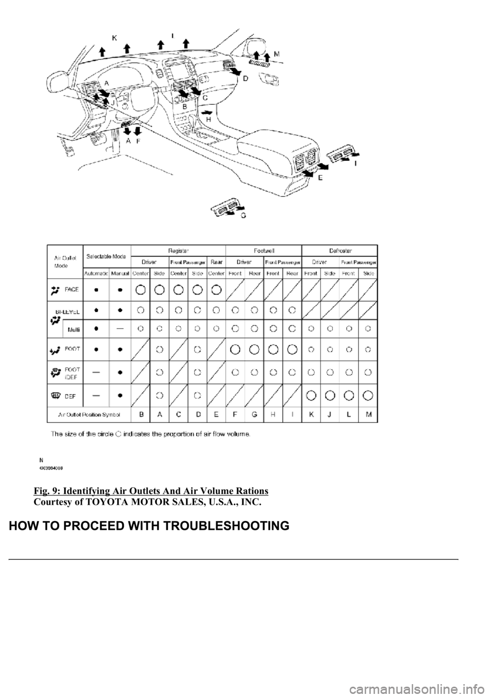
Fig. 9: Identifying Air Outlets And Air Volume Rations
Courtesy of TOYOTA MOTOR SALES, U.S.A., INC.
Page 214 of 4500

The hand-held tester can be used in steps 3, 6, 7 and 11.
1.VEHICLE BROUGHT TO WORK SHOP
2.(SEE CUSTOMER PROBLEM ANALYSIS CHECK
)
a. Confirm problem symptoms.
3.CHECK AND CLEAR THE DTCS (SEE DTC CHECK/CLEAR
)
4.PROBLEM SYMPTOM CONFIRMATION
SYMPTOM OCCURS (GO TO STEP 6)
SYMPTOM DOES NOT OCCUR (GO TO STEP 5)
5.SYMPTOM SIMULATION (SEE HOW TO PROCEED WITH TROUBLESHOOTING
)
6.CHECK BODY MULTIPLEX COMMUNICATION SYSTEM (SEE HOW TO PROCEED WITH
TROUBLESHOOTING )
a. Check for the DTC output.
MULTIPLEX DTC OUTPUTS (PROCEED TO "MULTIPLEX COMMUNICATION SYSTEM
")
NO MULTIPLEX DTC (GO TO STEP 7)
7.CHECK CAN COMMUNICATION SYSTEM (SEE HOW TO PROCEED WITH
TROUBLESHOOTING )
a. Check for the DTC output.
CAN DTC OUTPUTS (PROCEED TO "CAN COMMUNICATION SYSTEM
")
NO CAN DTC (GO TO STEP 8)
8.DTC CHECK (OTHER THAN MULTIPLEX DTC) (SEE DTC CHECK/CLEAR
)
MALFUNCTION CODE (GO TO STEP 9)
NORMAL CODE (GO TO STEP 10)
9.(SEE DIAGNOSTIC TROUBLE CODE CHART
)
GO TO STEP 12
10.(SEE PROBLEM SYMPTOMS TABLE
)
11.(SEE ACTUATOR CHECK
)
12.CIRCUIT INSPECTION (SEE DTC B1411 ROOM TEMPERATURE SENSOR CIRCUIT
to
INTELLIGENT SWING REGISTER CIRCUIT
)
13.IDENTIFYING OF PROBLEMS
Page 215 of 4500
14.PARTS INSPECTION
15.REPAIR
16.CONFIRMATION TEST
END
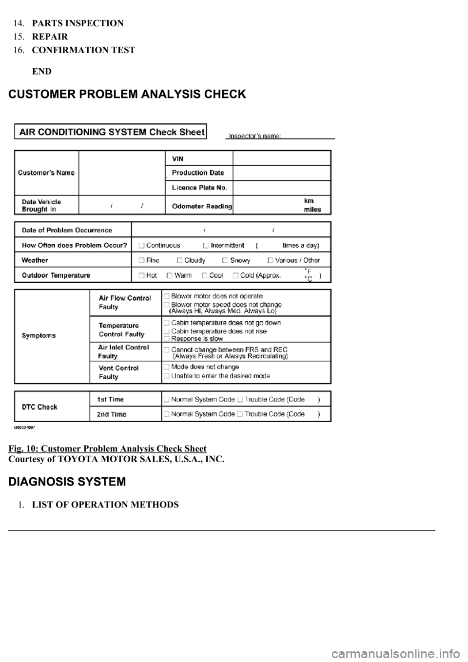
Fig. 10: Customer Problem Analysis Check Sheet
Courtesy of TOYOTA MOTOR SALES, U.S.A., INC.
1.LIST OF OPERATION METHODS
Page 216 of 4500
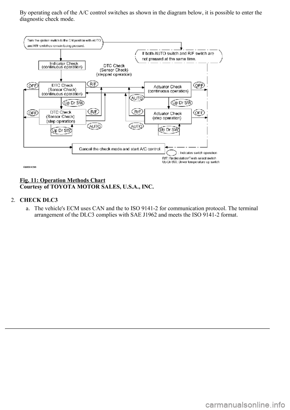
By operating each of the A/C control switches as shown in the diagram below, it is possible to enter the
diagnostic check mode.
Fig. 11: Operation Methods Chart
Courtesy of TOYOTA MOTOR SALES, U.S.A., INC.
2.CHECK DLC3
a. The vehicle's ECM uses CAN and the to ISO 9141-2 for communication protocol. The terminal
arrangement of the DLC3 complies with SAE J1962 and meets the ISO 9141-2 format.
Page 217 of 4500
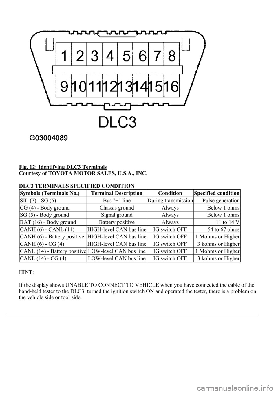
Fig. 12: Identifying DLC3 Terminals
Courtesy of TOYOTA MOTOR SALES, U.S.A., INC.
DLC3 TERMINALS SPECIFIED CONDITION
HINT:
If the display shows UNABLE TO CONNECT TO VEHICLE when you have connected the cable of the
hand-held tester to the DLC3, turned the ignition switch ON and operated the tester, there is a problem on
the vehicle side or tool side.
Symbols (Terminals No.)Terminal DescriptionConditionSpecified condition
SIL (7) - SG (5)Bus "+" lineDuring transmissionPulse generation
CG (4) - Body groundChassis groundAlwaysBelow 1 ohms
SG (5) - Body groundSignal groundAlwaysBelow 1 ohms
BAT (16) - Body groundBattery positiveAlways11 to 14 V
CANH (6) - CANL (14)HIGH-level CAN bus lineIG switch OFF54 to 67 ohms
CANH (6) - Battery positiveHIGH-level CAN bus lineIG switch OFF1 Mohms or Higher
CANH (6) - CG (4)HIGH-level CAN bus lineIG switch OFF3 kohms or Higher
CANL (14) - Battery positiveLOW-level CAN bus lineIG switch OFF1 Mohms or Higher
CANL (14) - CG (4)LOW-level CAN bus lineIG switch OFF3 kohms or Higher
Page 218 of 4500
If the communication is normal when the tool is connected to another vehicle, inspect the DLC3 on
the original vehicle.
If the communication is still impossible when the tool is connected to another vehicle, the problem
is probably in the tool itself, so consult the Service Department listed in the tool's instruction
manual.
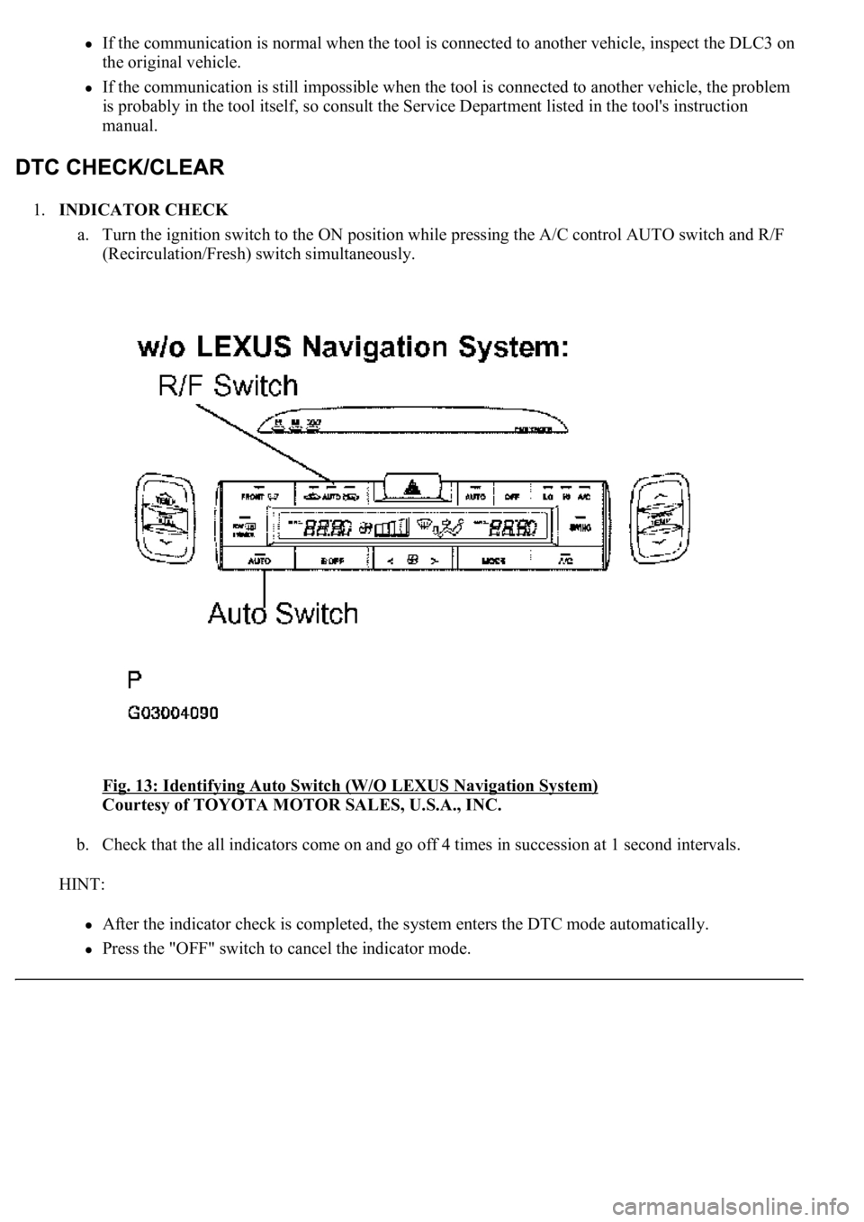
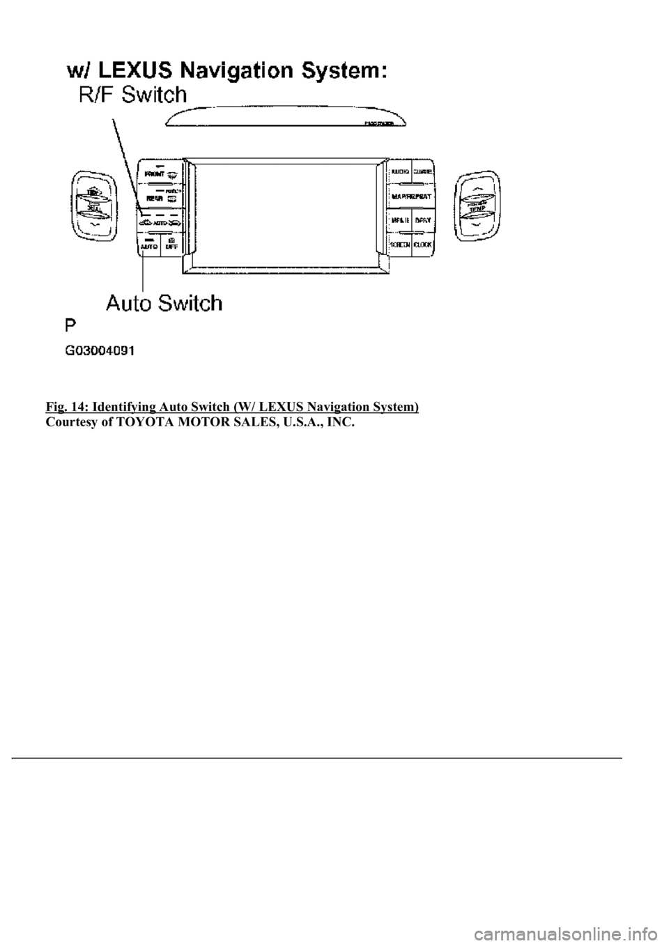
1.INDICATOR CHECK
a. Turn the ignition switch to the ON position while pressing the A/C control AUTO switch and R/F
(Recirculation/Fresh) switch simultaneously.
Fig. 13: Identifying Auto Switch (W/O LEXUS Navigation System)
Courtesy of TOYOTA MOTOR SALES, U.S.A., INC.
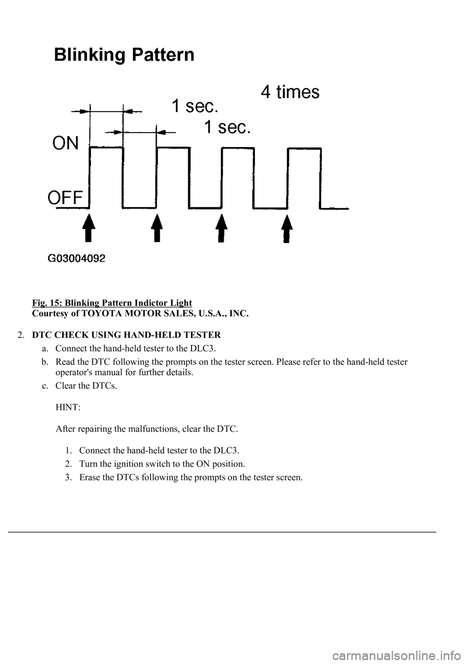
b. Check that the all indicators come on and go off 4 times in succession at 1 second intervals.
HINT:
After the indicator check is completed, the system enters the DTC mode automatically.
Press the "OFF" switch to cancel the indicator mode.
Page 219 of 4500
Fig. 14: Identifying Auto Switch (W/ LEXUS Navigation System)
Courtesy of TOYOTA MOTOR SALES, U.S.A., INC.
Page 220 of 4500
Fig. 15: Blinking Pattern Indictor Light
Courtesy of TOYOTA MOTOR SALES, U.S.A., INC.
2.DTC CHECK USING HAND-HELD TESTER
a. Connect the hand-held tester to the DLC3.
b. Read the DTC following the prompts on the tester screen. Please refer to the hand-held tester
operator's manual for further details.
c. Clear the DTCs.
HINT:
After repairing the malfunctions, clear the DTC.
1. Connect the hand-held tester to the DLC3.
2. Turn the ignition switch to the ON position.
3. Erase the DTCs followin
g the prompts on the tester screen.
Trending: airbag off, damper, keys, high beam, oil capacity, electronic modulated, mirror controls
