LEXUS LS430 2003 Factory Repair Manual
Manufacturer: LEXUS, Model Year: 2003,
Model line: LS430,
Model: LEXUS LS430 2003
Pages: 4500, PDF Size: 87.45 MB
LEXUS LS430 2003 Factory Repair Manual
LS430 2003
LEXUS
LEXUS
https://www.carmanualsonline.info/img/36/57050/w960_57050-0.png
LEXUS LS430 2003 Factory Repair Manual
Trending: coolant, replacement, B1278, tensioner pulley, change wheel, idler tensioner pulley, sat nav
Page 201 of 4500
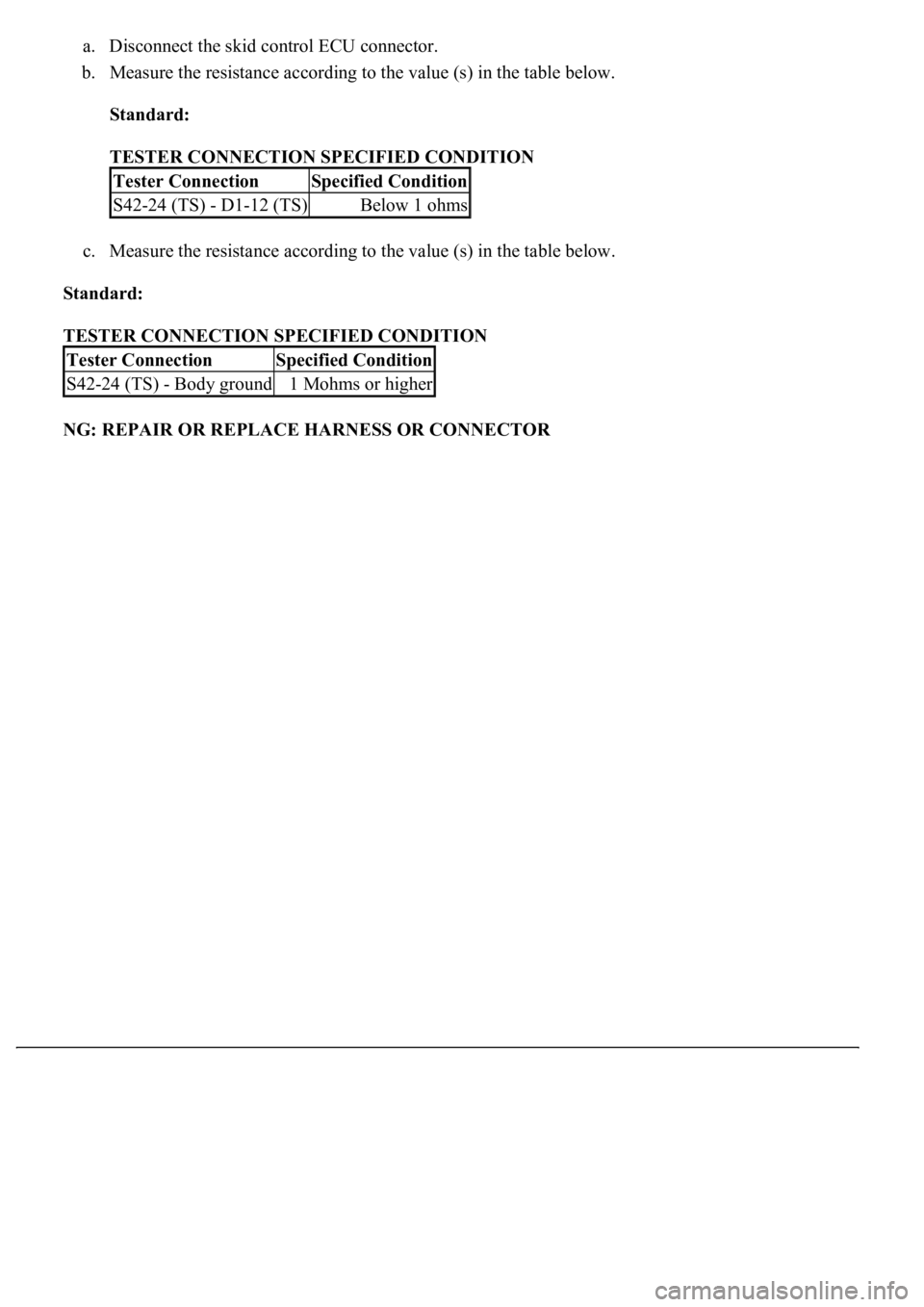
a. Disconnect the skid control ECU connector.
b. Measure the resistance according to the value (s) in the table below.
Standard:
TESTER CONNECTION SPECIFIED CONDITION
c. Measure the resistance according to the value (s) in the table below.
Standard:
TESTER CONNECTION SPECIFIED CONDITION
NG: REPAIR OR REPLACE HARNESS OR CONNECTOR
Tester ConnectionSpecified Condition
S42-24 (TS) - D1-12 (TS)Below 1 ohms
Tester ConnectionSpecified Condition
S42-24 (TS) - Body ground1 Mohms or higher
Page 202 of 4500
Fig. 142: Identifying Skid Control ECU Terminals
Courtesy of TOYOTA MOTOR SALES, U.S.A., INC.
OK: REPLACE ABS & TRACTION ACTUATOR ASSY (SEE REPLACEMENT
)
Page 203 of 4500
Page 204 of 4500
FRONT POWER SEAT CONTROL SYSTEM REFERENCE
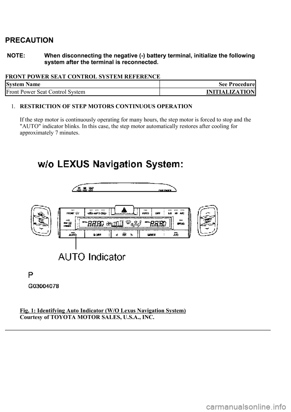
1.RESTRICTION OF STEP MOTORS CONTINUOUS OPERATION
If the step motor is continuously operating for many hours, the step motor is forced to stop and the
"AUTO" indicator blinks. In this case, the step motor automatically restores after cooling for
approximately 7 minutes.
Fig. 1: Identifying Auto Indicator (W/O Lexus Navigation System)
Courtesy of TOYOTA MOTOR SALES, U.S.A., INC.
System NameSee Procedure
Front Power Seat Control SystemINITIALIZATION
Page 205 of 4500
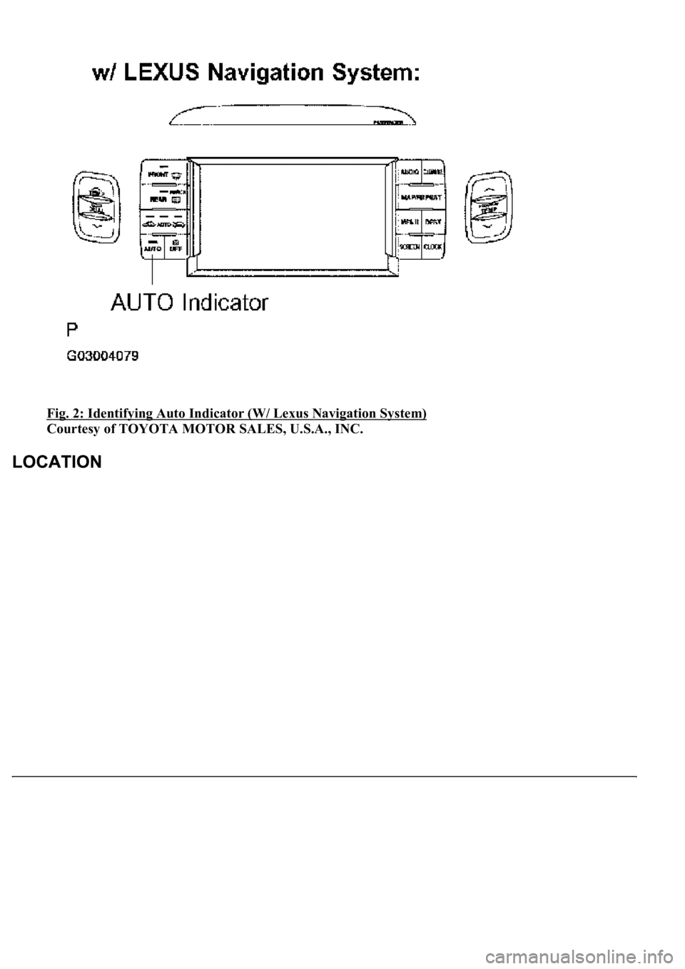
Fig. 2: Identifying Auto Indicator (W/ Lexus Navigation System)
Courtesy of TOYOTA MOTOR SALES, U.S.A., INC.
Page 206 of 4500
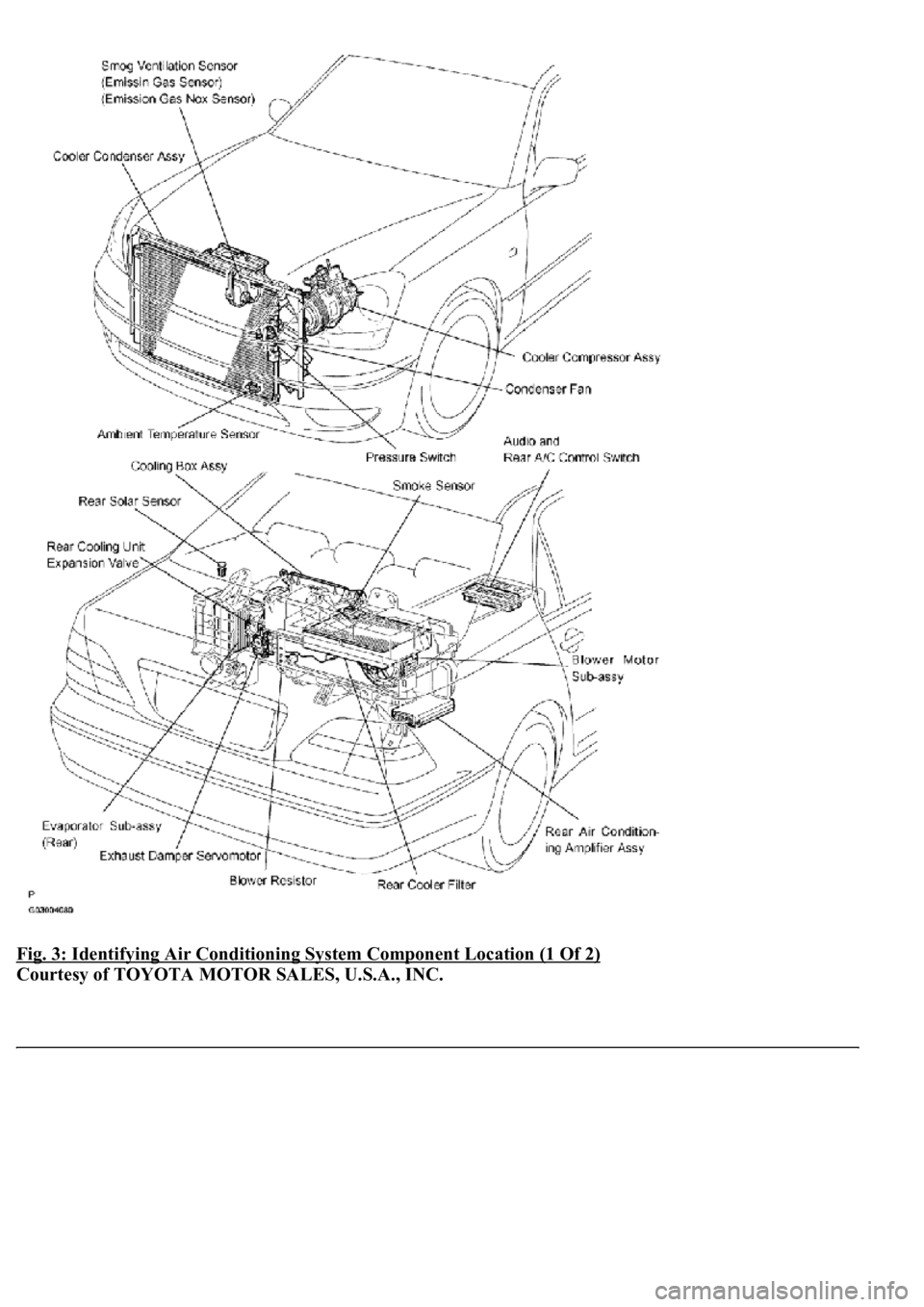
Fig. 3: Identifying Air Conditioning System Component Location (1 Of 2)
Courtesy of TOYOTA MOTOR SALES, U.S.A., INC.
Page 207 of 4500
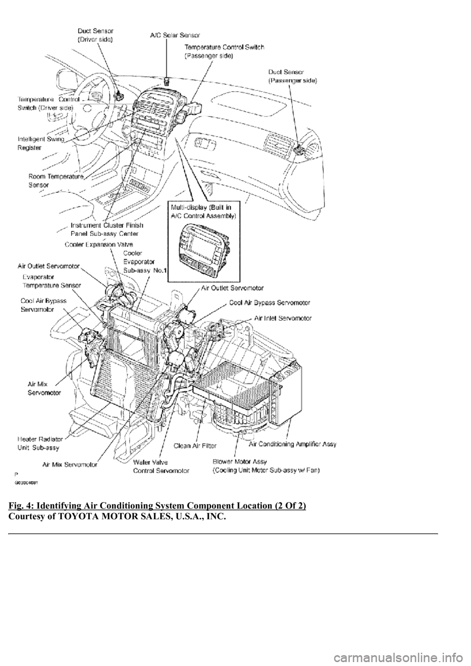
Fig. 4: Identifying Air Conditioning System Component Location (2 Of 2)
Courtesy of TOYOTA MOTOR SALES, U.S.A., INC.
Page 208 of 4500
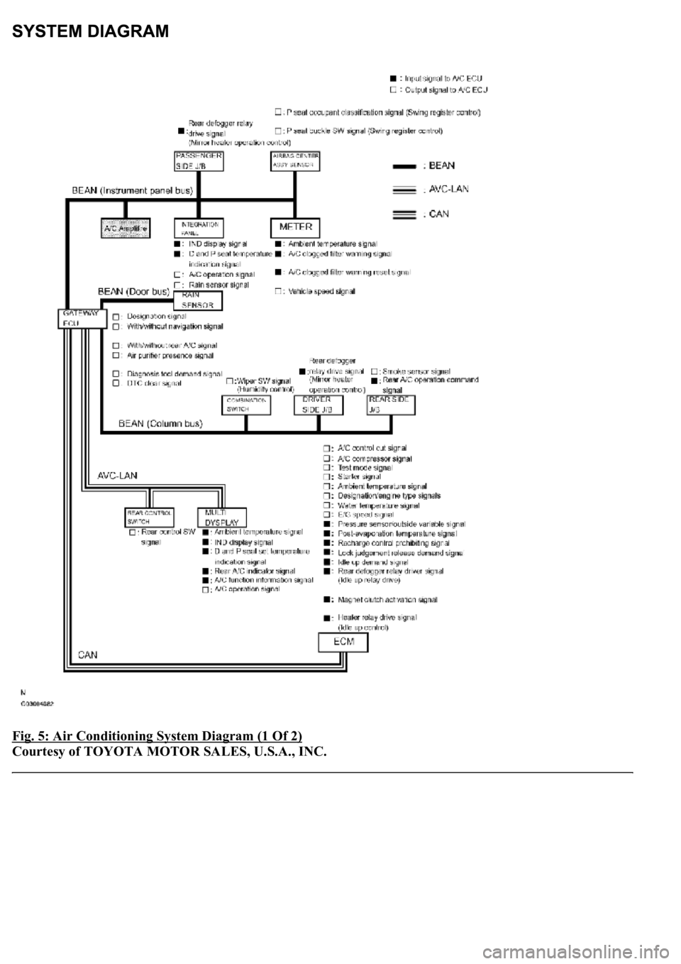
Fig. 5: Air Conditioning System Diagram (1 Of 2)
Courtesy of TOYOTA MOTOR SALES, U.S.A., INC.
Page 209 of 4500
Page 210 of 4500
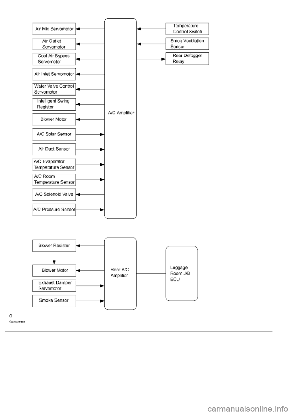
Fig. 6: Air Conditioning System Diagram (2 Of 2)
Courtesy of TOYOTA MOTOR SALES, U.S.A., INC.
1.GENERAL
a. The air conditioning system has the following features:
In compliance with the temperature set at the temperature control switch, the neural network
control calculates the outlet temperature based on the input signals from various sensors. In
addition, corrections in accordance with the signals from the evaporative temperature sensor
and the water temperature sensor are added to control the outlet air temperature.
Controls the front and rear blower motors in accordance with the airflow volume that has
been calculated by the neural network control based on the input signals from various
sensors.
Automatically switches the outlets in accordance with the outlet mode ratio that has been
calculated by the neural network control based on the input signals from various sensors.
Automatically controls the air inlet control damper in accordance with the airflow volume
that has been calculated by the neural network control.
Turns the compressor on/off and controls the discharge capacity based on the signals from
various sensors.
Based on the signals from the ambient temperature sensor, this control calculates the outside
temperature, which is then corrected in the air conditioner ECU, and shown in the multi-
information display in the combination meter.
Switched the rear defogger and outside rear view mirror heaters on for 15 minutes when the
rear defogger switch is switched on. Switched them off if the switch is pressed while they are
operating.
Controls the orientation and the angle of the front center register based on the input signals
from various sensors and on the outlet mode.
Determines whether the clean air filter (for the front A/C) is clogged by monitoring the air
inlets, and airflow volume.
The A/C amplifier automatically controls the air inlets based on the signals from the smog
ventilation sensor.
Improves the air quality by linking the air inlet control damper and the blower motor (for the
rear A/C and air purifier), based on the signals from the exhaust gas sensor and the smoke
sensor.
Checks the sensors in accordance with operation of the air conditioner switches.
2.MODEL POSITION AND DAMPER OPERATION
Trending: climate control, mileage, oil pressure, battery, remote control, mirror controls, instrument panel
