LEXUS LS430 2003 Factory Repair Manual
Manufacturer: LEXUS, Model Year: 2003,
Model line: LS430,
Model: LEXUS LS430 2003
Pages: 4500, PDF Size: 87.45 MB
LEXUS LS430 2003 Factory Repair Manual
LS430 2003
LEXUS
LEXUS
https://www.carmanualsonline.info/img/36/57050/w960_57050-0.png
LEXUS LS430 2003 Factory Repair Manual
Trending: phone, rear seat, fuel system, low beam, automatic transmission, bluetooth, brake
Page 251 of 4500
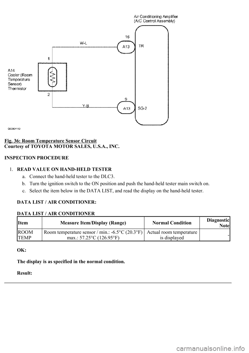
Fig. 36: Room Temperature Sensor Circuit
Courtesy of TOYOTA MOTOR SALES, U.S.A., INC.
INSPECTION PROCEDURE
1.READ VALUE ON HAND-HELD TESTER
a. Connect the hand-held tester to the DLC3.
b. Turn the ignition switch to the ON position and push the hand-held tester main switch on.
c. Select the item below in the DATA LIST, and read the display on the hand-held tester.
DATA LIST / AIR CONDITIONER:
DATA LIST / AIR CONDITIONER
OK:
The display is as specified in the normal condition.
Result:
ItemMeasure Item/Display (Range)Normal ConditionDiagnostic
Note
ROOM
TEMPRoom temperature sensor / min.: -6.5°C (20.3°F)
max.: 57.25°C (126.95°F)Actual room temperature
is displayed-
Page 252 of 4500
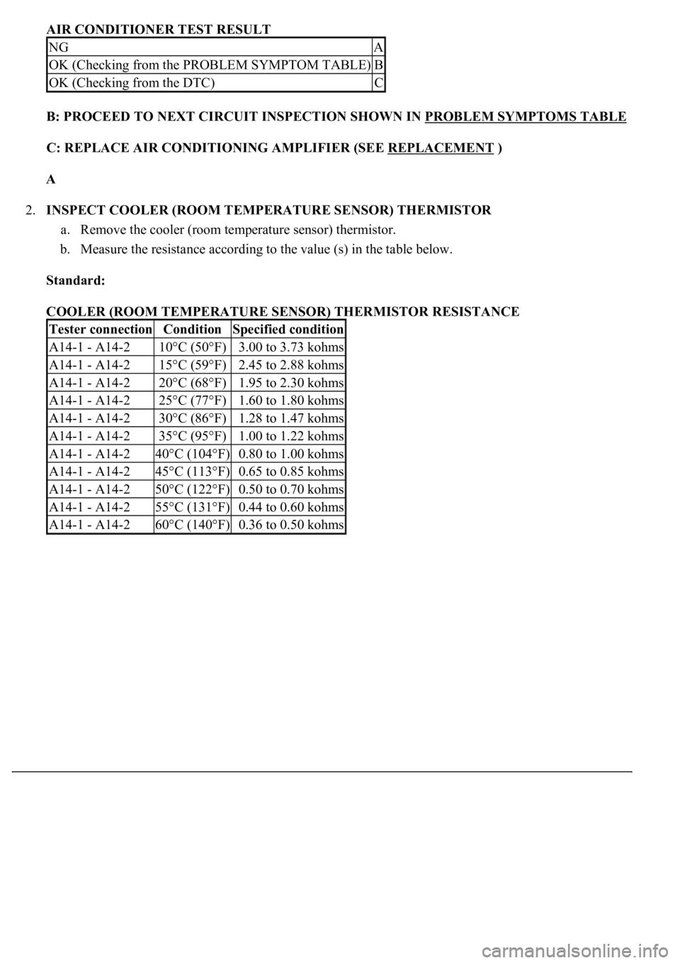
AIR CONDITIONER TEST RESULT
B: PROCEED TO NEXT CIRCUIT INSPECTION SHOWN IN PROBLEM SYMPTOMS TABLE
C: REPLACE AIR CONDITIONING AMPLIFIER (SEE REPLACEMENT )
A
2.INSPECT COOLER (ROOM TEMPERATURE SENSOR) THERMISTOR
a. Remove the cooler (room temperature sensor) thermistor.
b. Measure the resistance according to the value (s) in the table below.
Standard:
COOLER (ROOM TEMPERATURE SENSOR) THERMISTOR RESISTANCE
NGA
OK (Checking from the PROBLEM SYMPTOM TABLE)B
OK (Checking from the DTC)C
Tester connectionConditionSpecified condition
A14-1 - A14-210°C (50°F)3.00 to 3.73 kohms
A14-1 - A14-215°C (59°F)2.45 to 2.88 kohms
A14-1 - A14-220°C (68°F)1.95 to 2.30 kohms
A14-1 - A14-225°C (77°F)1.60 to 1.80 kohms
A14-1 - A14-230°C (86°F)1.28 to 1.47 kohms
A14-1 - A14-235°C (95°F)1.00 to 1.22 kohms
A14-1 - A14-240°C (104°F)0.80 to 1.00 kohms
A14-1 - A14-245°C (113°F)0.65 to 0.85 kohms
A14-1 - A14-250°C (122°F)0.50 to 0.70 kohms
A14-1 - A14-255°C (131°F)0.44 to 0.60 kohms
A14-1 - A14-260°C (140°F)0.36 to 0.50 kohms
Page 253 of 4500
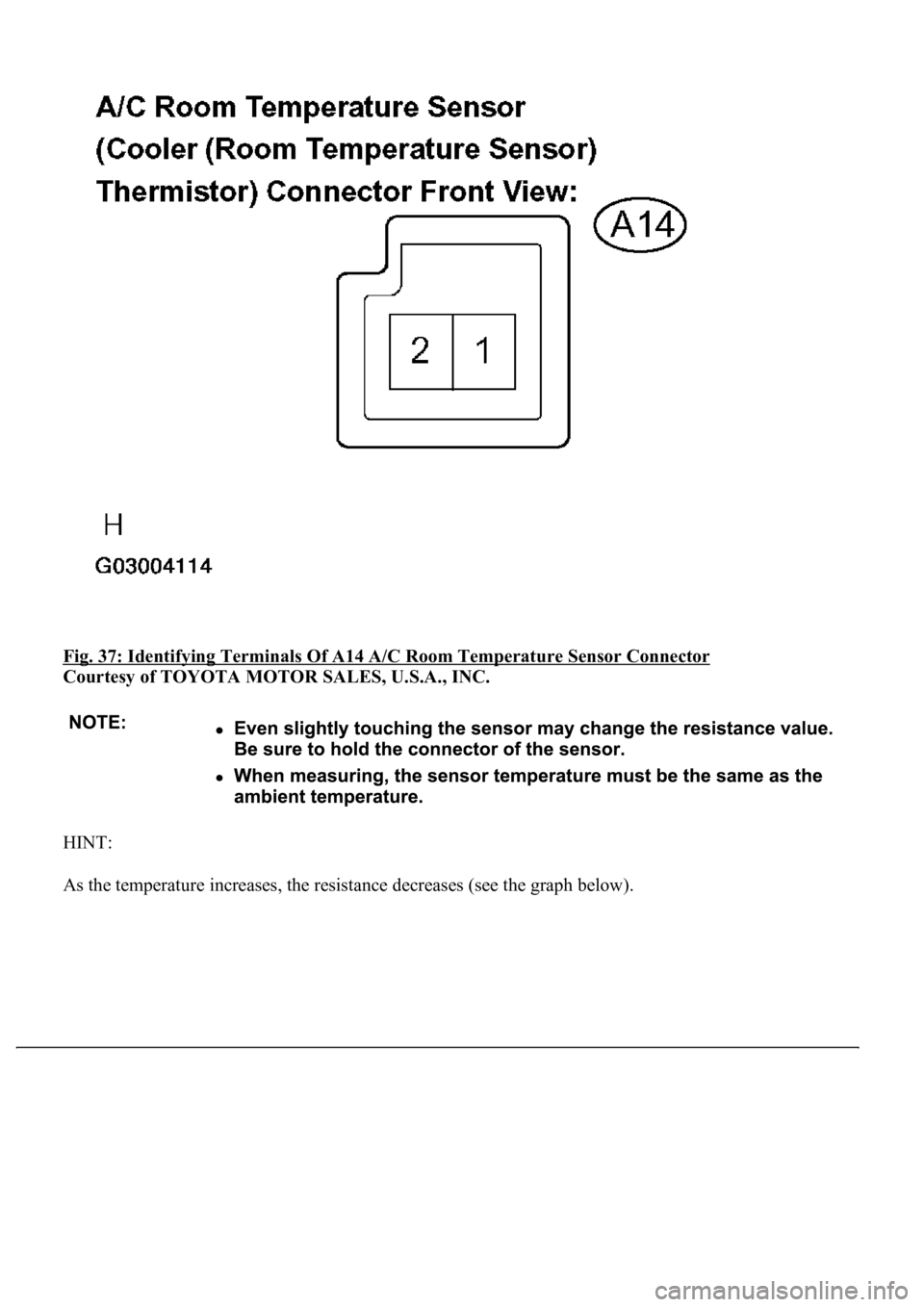
Fig. 37: Identifying Terminals Of A14 A/C Room Temperature Sensor Connector
Courtesy of TOYOTA MOTOR SALES, U.S.A., INC.
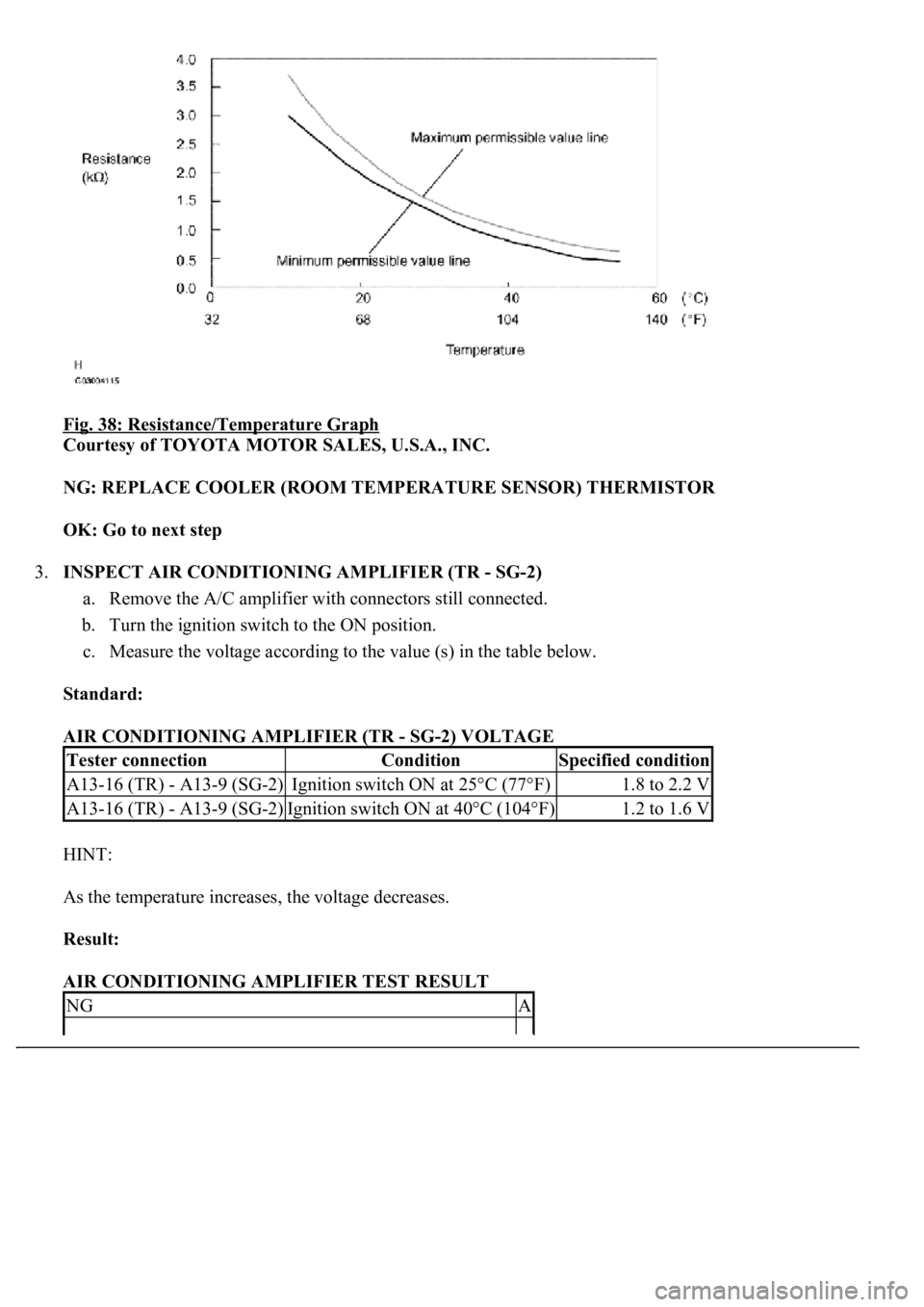
HINT:
As the temperature increases, the resistance decreases (see the
graph below).
Page 254 of 4500
Fig. 38: Resistance/Temperature Graph
Courtesy of TOYOTA MOTOR SALES, U.S.A., INC.
NG: REPLACE COOLER (ROOM TEMPERATURE SENSOR) THERMISTOR
OK: Go to next step
3.INSPECT AIR CONDITIONING AMPLIFIER (TR - SG-2)
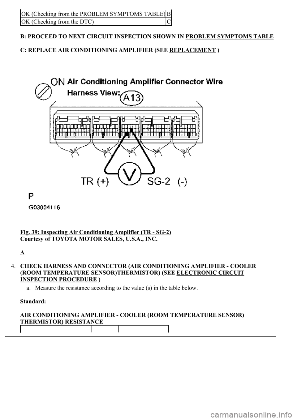
a. Remove the A/C amplifier with connectors still connected.
b. Turn the ignition switch to the ON position.
c. Measure the voltage according to the value (s) in the table below.
Standard:
AIR CONDITIONING AMPLIFIER (TR - SG-2) VOLTAGE
HINT:
As the temperature increases, the voltage decreases.
Result:
AIR CONDITIONING AMPLIFIER TEST RESULT
Tester connectionConditionSpecified condition
A13-16 (TR) - A13-9 (SG-2)Ignition switch ON at 25°C (77°F)1.8 to 2.2 V
A13-16 (TR) - A13-9 (SG-2)Ignition switch ON at 40°C (104°F)1.2 to 1.6 V
NGA
Page 255 of 4500
B: PROCEED TO NEXT CIRCUIT INSPECTION SHOWN IN PROBLEM SYMPTOMS TABLE
C: REPLACE AIR CONDITIONING AMPLIFIER (SEE REPLACEMENT )
Fig. 39: Inspecting Air Conditioning Amplifier (TR
- SG-2)
Courtesy of TOYOTA MOTOR SALES, U.S.A., INC.
A
4.CHECK HARNESS AND CONNECTOR (AIR CONDITIONING AMPLIFIER - COOLER
(ROOM TEMPERATURE SENSOR)THERMISTOR) (SEE ELECTRONIC CIRCUIT
INSPECTION PROCEDURE )
a. Measure the resistance according to the value (s) in the table below.
Standard:
AIR CONDITIONING AMPLIFIER - COOLER (ROOM TEMPERATURE SENSOR)
THERMISTOR) RESISTANCE
OK (Checking from the PROBLEM SYMPTOMS TABLE)B
OK (Checking from the DTC)C
Page 256 of 4500
NG: REPAIR OR REPLACE HARNESS OR CONNECTOR
Tester connectionConditionSpecified condition
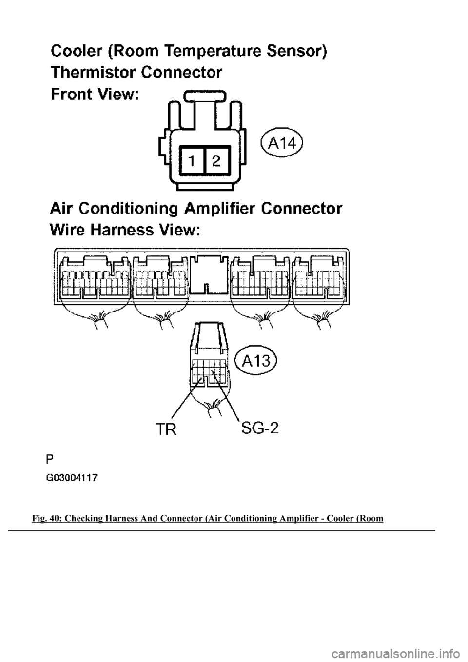
A13-16 (TR) - A14-1AlwaysBelow 1 ohms
A13-9 (SG-2) - A14-2AlwaysBelow 1 ohms
A13-16 (TR) - Body groundAlways10 kohms or higher
A13-9 (SG-2) - Body groundAlwaysBelow 1 ohms
Page 257 of 4500
Fig. 40: Checking Harness And Connector (Air Conditioning Amplifier - Cooler (Room
Page 258 of 4500
Temperature Sensor)Thermistor)
Courtesy of TOYOTA MOTOR SALES, U.S.A., INC.
OK: REPLACE AIR CONDITIONING AMPLIFIER (SEE REPLACEMENT
)
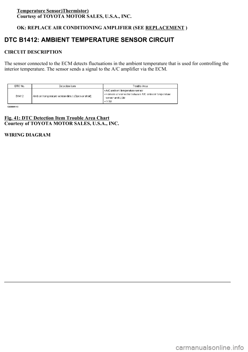
CIRCUIT DESCRIPTION
The sensor connected to the ECM detects fluctuations in the ambient temperature that is used for controlling the
interior temperature. The sensor sends a signal to the A/C amplifier via the ECM.
Fig. 41: DTC Detection Item Trouble Area Chart
Courtesy of TOYOTA MOTOR SALES, U.S.A., INC.
WIRING DIAGRAM
Page 259 of 4500
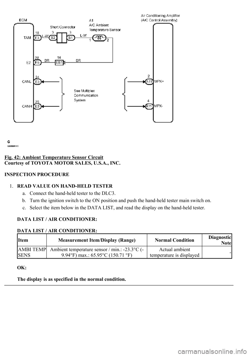
Fig. 42: Ambient Temperature Sensor Circuit
Courtesy of TOYOTA MOTOR SALES, U.S.A., INC.
INSPECTION PROCEDURE
1.READ VALUE ON HAND-HELD TESTER
a. Connect the hand-held tester to the DLC3.
b. Turn the ignition switch to the ON position and push the hand-held tester main switch on.
c. Select the item below in the DATA LIST, and read the display on the hand-held tester.
DATA LIST / AIR CONDITIONER:
DATA LIST / AIR CONDITIONER:
OK:
The display is as specified in the normal condition.
ItemMeasurement Item/Display (Range)Normal ConditionDiagnostic
Note
AMBI TEMP
SENSAmbient temperature sensor / min.: -23.3°C (-
9.94°F) max.: 65.95°C (150.71 °F)Actual ambient
temperature is displayed-
Page 260 of 4500
Result:
AIR CONDITIONER TEST RESULT
B: PROCEED TO NEXT CIRCUIT INSPECTION SHOWN IN PROBLEM SYMPTOMS TABLE
C: REPLACE AIR CONDITIONING AMPLIFIER (SEE REPLACEMENT )
A
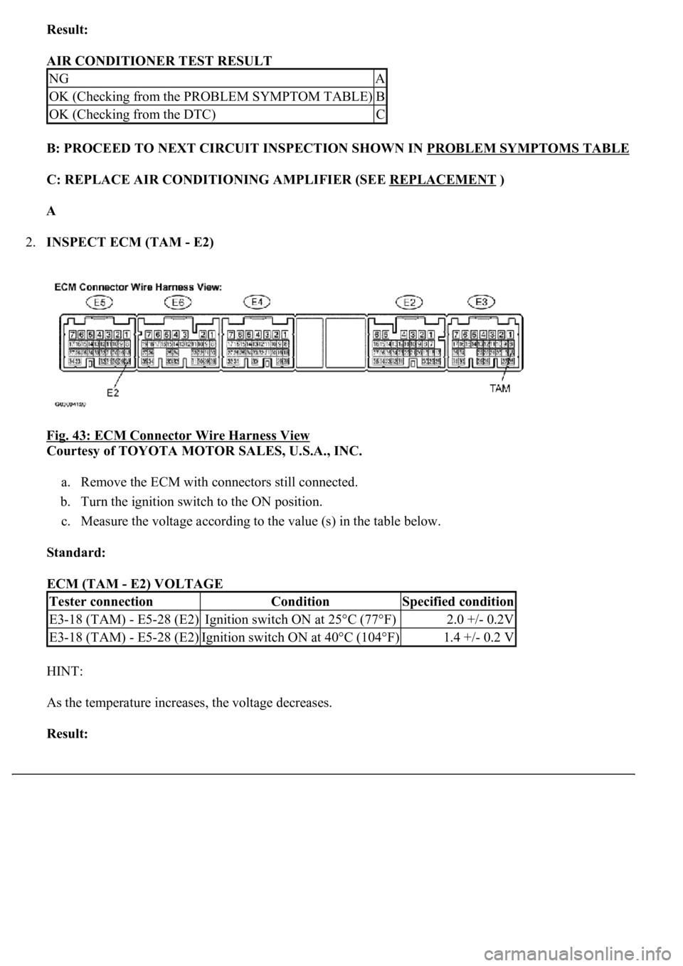
2.INSPECT ECM (TAM - E2)
Fig. 43: ECM Connector Wire Harness View
Courtesy of TOYOTA MOTOR SALES, U.S.A., INC.
a. Remove the ECM with connectors still connected.
b. Turn the ignition switch to the ON position.
c. Measure the voltage according to the value (s) in the table below.
Standard:
ECM (TAM - E2) VOLTAGE
HINT:
As the temperature increases, the voltage decreases.
Result:
NGA
OK (Checking from the PROBLEM SYMPTOM TABLE)B
OK (Checking from the DTC)C
Tester connectionConditionSpecified condition
E3-18 (TAM) - E5-28 (E2)Ignition switch ON at 25°C (77°F)2.0 +/- 0.2V
E3-18 (TAM) - E5-28 (E2)Ignition switch ON at 40°C (104°F)1.4 +/- 0.2 V
Trending: B2402, content, high beam, Sp2, cruise control, roof rack, oil capacity
