LEXUS LS430 2003 Factory Repair Manual
Manufacturer: LEXUS, Model Year: 2003,
Model line: LS430,
Model: LEXUS LS430 2003
Pages: 4500, PDF Size: 87.45 MB
LEXUS LS430 2003 Factory Repair Manual
LS430 2003
LEXUS
LEXUS
https://www.carmanualsonline.info/img/36/57050/w960_57050-0.png
LEXUS LS430 2003 Factory Repair Manual
Trending: sat nav, fuel cap, engine oil, warning lights, transmission oil, trunk, air filter
Page 241 of 4500
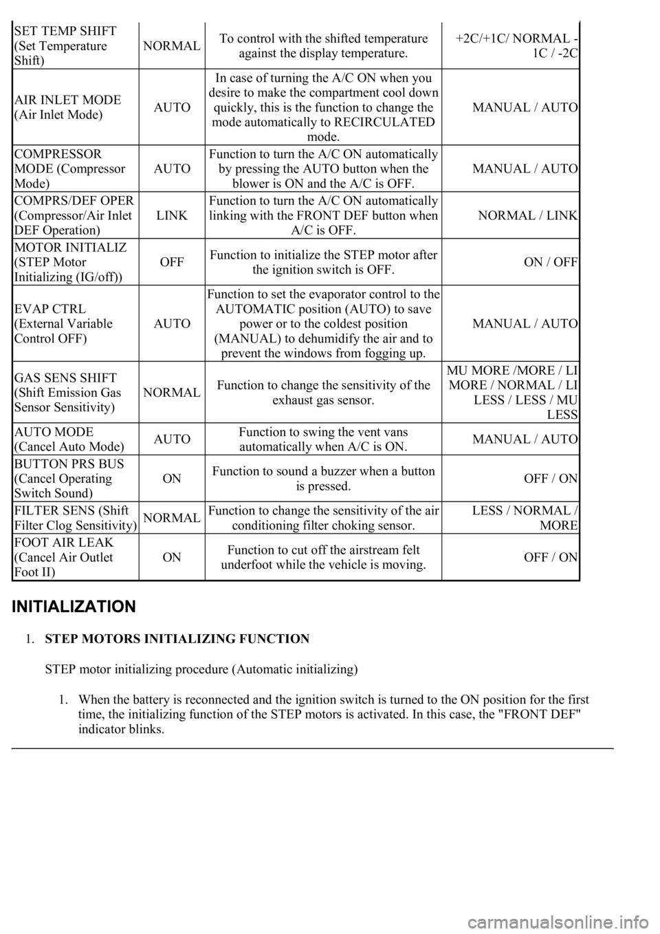
1.STEP MOTORS INITIALIZING FUNCTION
STEP motor initializing procedure (Automatic initializing)
1. When the battery is reconnected and the ignition switch is turned to the ON position for the first
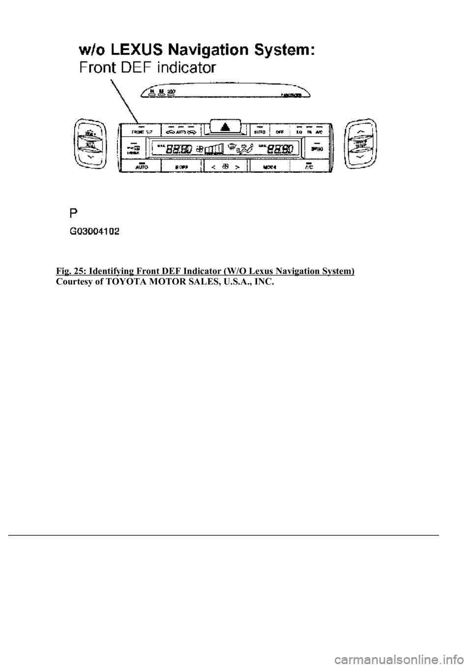
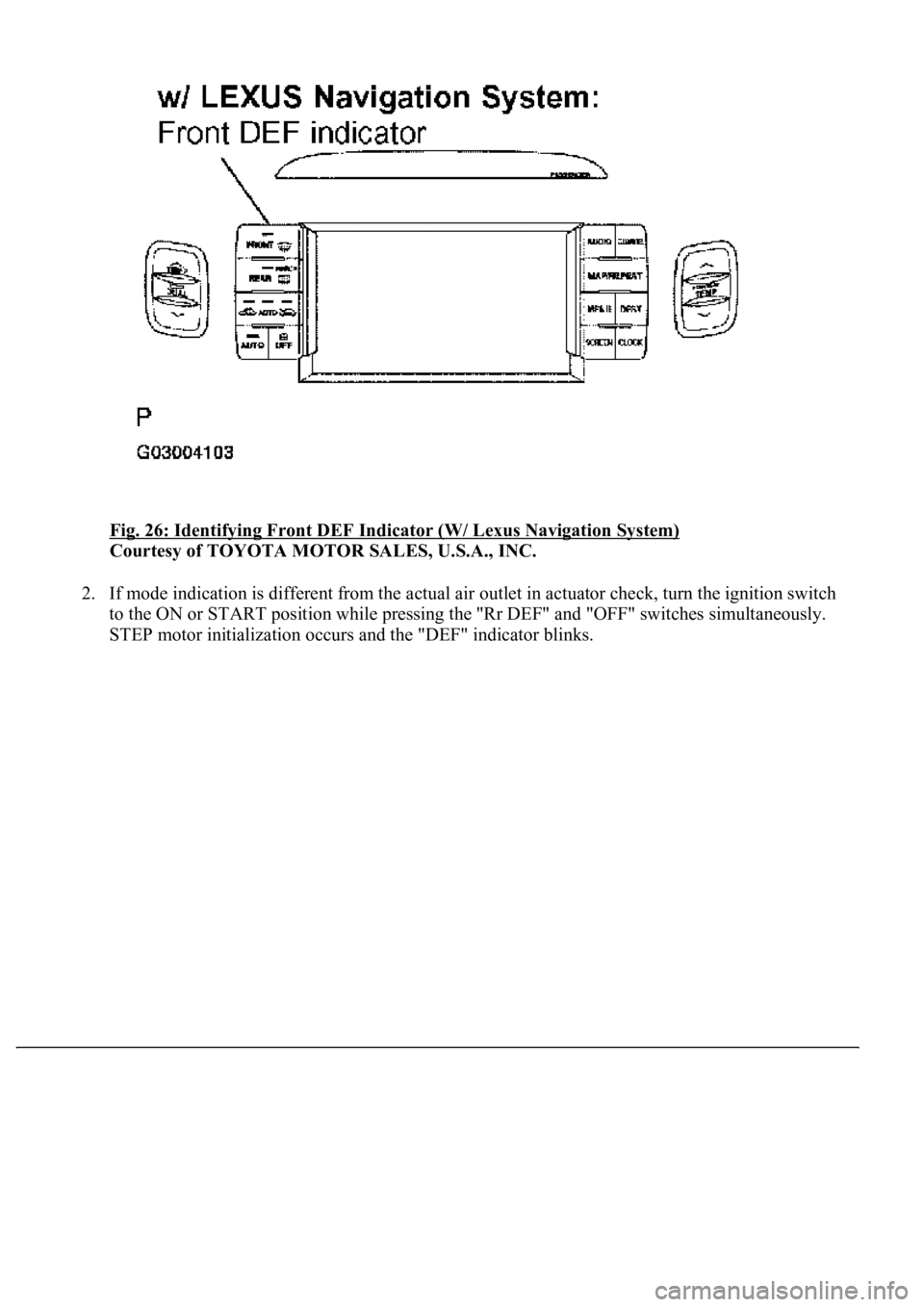
time, the initializing function of the STEP motors is activated. In this case, the "FRONT DEF"
indicator blinks.
SET TEMP SHIFT
(Set Temperature
Shift)
NORMALTo control with the shifted temperature
against the display temperature.+2C/+1C/ NORMAL -
1C / -2C
AIR INLET MODE
(Air Inlet Mode)AUTO
In case of turning the A/C ON when you
desire to make the compartment cool down
quickly, this is the function to change the
mode automatically to RECIRCULATED
mode.
MANUAL / AUTO
COMPRESSOR
MODE (Compressor
Mode)
AUTO
Function to turn the A/C ON automatically
by pressing the AUTO button when the
blower is ON and the A/C is OFF.
MANUAL / AUTO
COMPRS/DEF OPER
(Compressor/Air Inlet
DEF Operation)
LINK
Function to turn the A/C ON automatically
linking with the FRONT DEF button when
A/C is OFF.
NORMAL / LINK
MOTOR INITIALIZ
(STEP Motor
Initializing (IG/off))
OFFFunction to initialize the STEP motor after
the ignition switch is OFF.ON / OFF
EVAP CTRL
(External Variable
Control OFF)
AUTO
Function to set the evaporator control to the
AUTOMATIC position (AUTO) to save
power or to the coldest position
(MANUAL) to dehumidify the air and to
prevent the windows from fogging up.
MANUAL / AUTO
GAS SENS SHIFT
(Shift Emission Gas
Sensor Sensitivity)
NORMALFunction to change the sensitivity of the
exhaust gas sensor.
MU MORE /MORE / LI
MORE / NORMAL / LI
LESS / LESS / MU
LESS
AUTO MODE
(Cancel Auto Mode)AUTOFunction to swing the vent vans
automatically when A/C is ON.MANUAL / AUTO
BUTTON PRS BUS
(Cancel Operating
Switch Sound)
ONFunction to sound a buzzer when a button
is pressed.OFF / ON
FILTER SENS (Shift
Filter Clog Sensitivity)NORMALFunction to change the sensitivity of the air
conditioning filter choking sensor.LESS / NORMAL /
MORE
FOOT AIR LEAK
(Cancel Air Outlet
Foot II)
ONFunction to cut off the airstream felt
underfoot while the vehicle is moving.OFF / ON
Page 242 of 4500
Fig. 25: Identifying Front DEF Indicator (W/O Lexus Navigation System)
Courtesy of TOYOTA MOTOR SALES, U.S.A., INC.
Page 243 of 4500
Fig. 26: Identifying Front DEF Indicator (W/ Lexus Navigation System)
Courtesy of TOYOTA MOTOR SALES, U.S.A., INC.
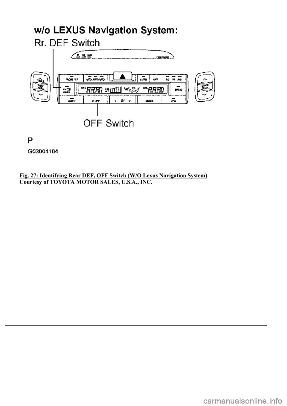
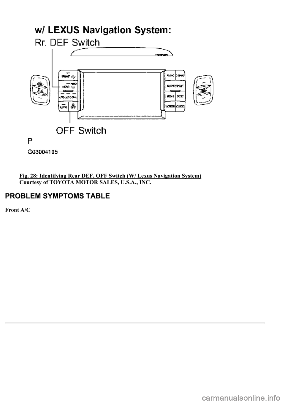
2. If mode indication is different from the actual air outlet in actuator check, turn the ignition switch
to the ON or START position while pressing the "Rr DEF" and "OFF" switches simultaneously.
STEP motor initialization occurs and the "DEF" indicator blinks.
Page 244 of 4500
Fig. 27: Identifying Rear DEF, OFF Switch (W/O Lexus Navigation System)
Courtesy of TOYOTA MOTOR SALES, U.S.A., INC.
Page 245 of 4500
Fig. 28: Identifying Rear DEF, OFF Switch (W/ Lexus Navigation System)
Courtesy of TOYOTA MOTOR SALES, U.S.A., INC.
Front A/C
Page 246 of 4500
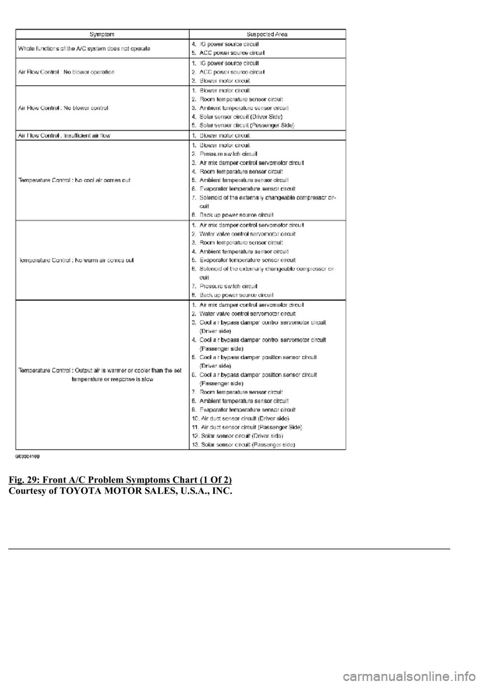
Fig. 29: Front A/C Problem Symptoms Chart (1 Of 2)
Courtesy of TOYOTA MOTOR SALES, U.S.A., INC.
Page 247 of 4500
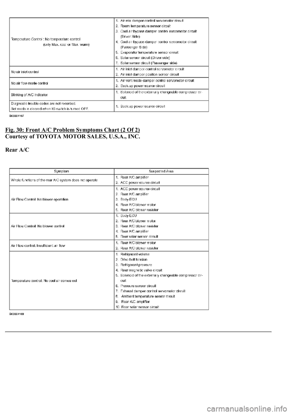
Fig. 30: Front A/C Problem Symptoms Chart (2 Of 2)
Courtesy of TOYOTA MOTOR SALES, U.S.A., INC.
Rear A/C
Page 248 of 4500

Fig. 31: Rear A/C Problem Symptoms Chart
Courtesy of TOYOTA MOTOR SALES, U.S.A., INC.
Air Purifier
Fig. 32: Air Purifier Problem Symptoms Chart
Courtesy of TOYOTA MOTOR SALES, U.S.A., INC.
Intelligent Swing Register
Fig. 33: Intelligent Swing Register Problem Symptoms Chart
Courtesy of TOYOTA MOTOR SALES, U.S.A., INC.
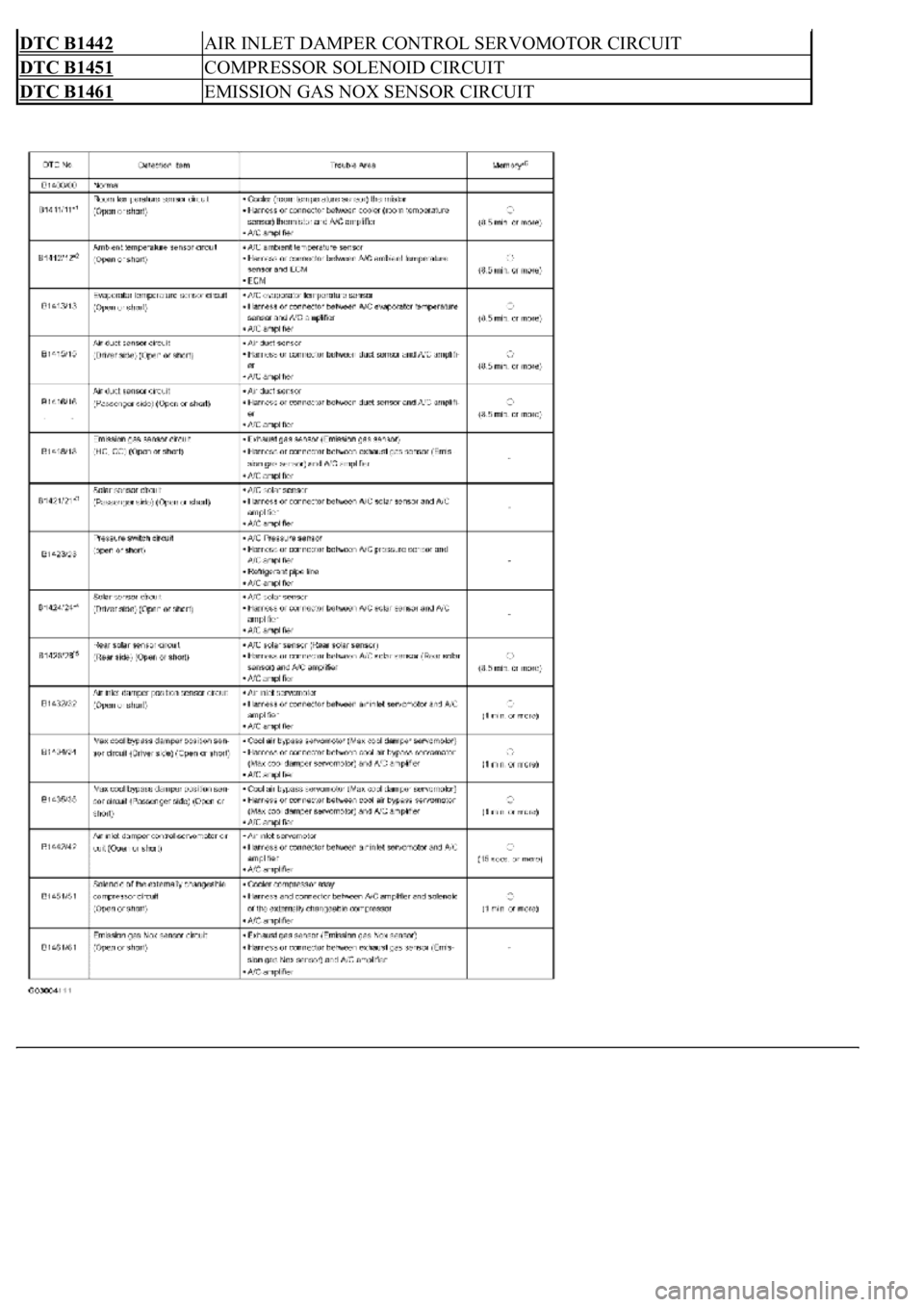
If a malfunction code is displayed during the DTC check (sensor check), check the circuit listed for that code in
the table below.
DIAGNOSTIC TROUBLE CODE CHART
DTCDescription
DTC B1411ROOM TEMPERATURE SENSOR CIRCUIT
DTC B1412AMBIENT TEMPERATURE SENSOR CIRCUIT
DTC B1413EVAPORATOR TEMPERATURE SENSOR CIRCUIT
DTC B1415AIR DUCT SENSOR CIRCUIT (DRIVER SIDE)
DTC B1416AIR DUCT SENSOR CIRCUIT (PASSENGER SIDE)
DTC B1418EMISSION GAS SENSOR CIRCUIT
DTC B1421SOLAR SENSOR CIRCUIT (PASSENGER SIDE)
DTC B1423PRESSURE SWITCH CIRCUIT
DTC B1424SOLAR SENSOR CIRCUIT (DRIVER SIDE)
DTC B1428REAR SOLAR SENSOR CIRCUIT
DTC B1432AIR INLET DAMPER POSITION SENSOR CIRCUIT
DTC B1434MAX COOL DAMPER POSITION SENSOR CIRCUIT (DRIVER SIDE)
DTC B1435MAX COOL DAMPER POSITION SENSOR CIRCUIT (PASSENGER SIDE)
Page 249 of 4500
DTC B1442AIR INLET DAMPER CONTROL SERVOMOTOR CIRCUIT
DTC B1451COMPRESSOR SOLENOID CIRCUIT
DTC B1461EMISSION GAS NOX SENSOR CIRCUIT
Page 250 of 4500
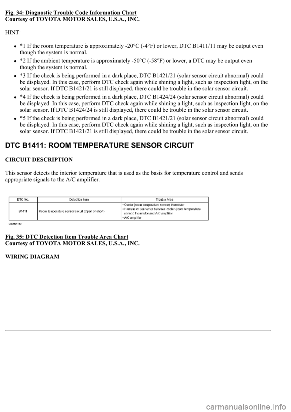
Fig. 34: Diagnostic Trouble Code Information Chart
Courtesy of TOYOTA MOTOR SALES, U.S.A., INC.
HINT:
*1 If the room temperature is approximately -20°C (-4°F) or lower, DTC B1411/11 may be output even
though the system is normal.
*2 If the ambient temperature is approximately -50°C (-58°F) or lower, a DTC may be output even
though the system is normal.
*3 If the check is being performed in a dark place, DTC B1421/21 (solar sensor circuit abnormal) could
be displayed. In this case, perform DTC check again while shining a light, such as inspection light, on the
solar sensor. If DTC B1421/21 is still displayed, there could be trouble in the solar sensor circuit.
*4 If the check is being performed in a dark place, DTC B1424/24 (solar sensor circuit abnormal) could
be displayed. In this case, perform DTC check again while shining a light, such as inspection light, on the
solar sensor. If DTC B1424/24 is still displayed, there could be trouble in the solar sensor circuit.
*5 If the check is being performed in a dark place, DTC B1421/21 (solar sensor circuit abnormal) could
be displayed. In this case, perform DTC check again while shining a light, such as inspection light, on the
solar sensor. If DTC B1421/21 is still displayed, there could be trouble in the solar sensor circuit.
CIRCUIT DESCRIPTION
This sensor detects the interior temperature that is used as the basis for temperature control and sends
appropriate signals to the A/C amplifier.
Fig. 35: DTC Detection Item Trouble Area Chart
Courtesy of TOYOTA MOTOR SALES, U.S.A., INC.
WIRING DIAGRAM
Trending: Soft hard, clock, airbag, fuel filter, mirror, B2419, B2419 bean

