LEXUS LS430 2003 Factory Repair Manual
Manufacturer: LEXUS, Model Year: 2003, Model line: LS430, Model: LEXUS LS430 2003Pages: 4500, PDF Size: 87.45 MB
Page 3961 of 4500
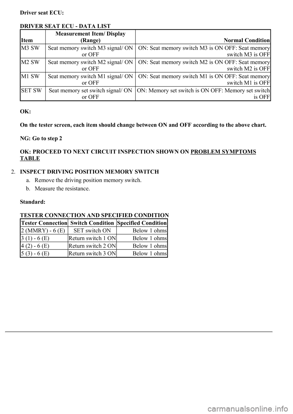
Driver seat ECU:
DRIVER SEAT ECU - DATA LIST
OK:
On the tester screen, each item should change between ON and OFF according to the above chart.
NG: Go to step 2
OK: PROCEED TO NEXT CIRCUIT INSPECTION SHOWN ON PROBLEM SYMPTOMS
TABLE
2.INSPECT DRIVING POSITION MEMORY SWITCH
a. Remove the driving position memory switch.
b. Measure the resistance.
Standard:
TESTER CONNECTION AND SPECIFIED CONDITION
Item
Measurement Item/ Display
(Range)
Normal Condition
M3 SWSeat memory switch M3 signal/ ON
or OFFON: Seat memory switch M3 is ON OFF: Seat memory
switch M3 is OFF
M2 SWSeat memory switch M2 signal/ ON
or OFFON: Seat memory switch M2 is ON OFF: Seat memory
switch M2 is OFF
M1 SWSeat memory switch M1 signal/ ON
or OFFON: Seat memory switch M1 is ON OFF: Seat memory
switch M1 is OFF
SET SWSeat memory set switch signal/ ON
or OFFON: Memory set switch is ON OFF: Memory set switch
is OFF
Tester ConnectionSwitch ConditionSpecified Condition
2 (MMRY) - 6 (E)SET switch ONBelow 1 ohms
3 (1) - 6 (E)Return switch 1 ONBelow 1 ohms
4 (2) - 6 (E)Return switch 2 ONBelow 1 ohms
5 (3) - 6 (E)Return switch 3 ONBelow 1 ohms
Page 3962 of 4500

Fig. 35: Identifying Driving Position Memory Switch Connector Terminals
Page 3963 of 4500
Courtesy of TOYOTA MOTOR SALES, U.S.A., INC.
NG: REPLACE DRIVING POSITION MEMORY SWITCH
OK: GO TO NEXT STEP
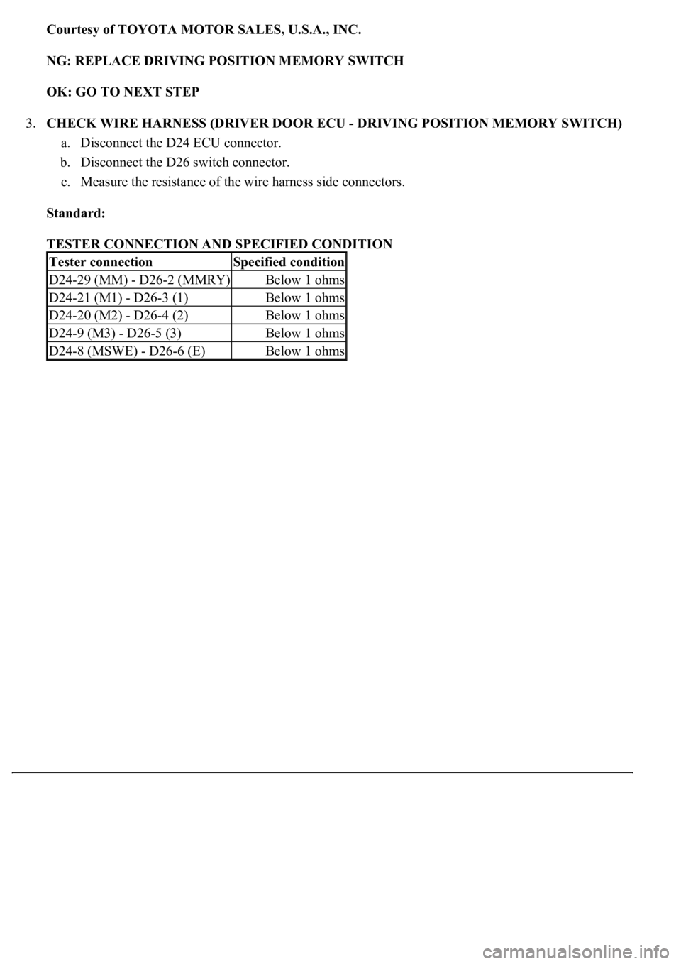
3.CHECK WIRE HARNESS (DRIVER DOOR ECU - DRIVING POSITION MEMORY SWITCH)
a. Disconnect the D24 ECU connector.
b. Disconnect the D26 switch connector.
c. Measure the resistance of the wire harness side connectors.
Standard:
TESTER CONNECTION AND SPECIFIED CONDITION
Tester connectionSpecified condition
D24-29 (MM) - D26-2 (MMRY)Below 1 ohms
D24-21 (M1) - D26-3 (1)Below 1 ohms
D24-20 (M2) - D26-4 (2)Below 1 ohms
D24-9 (M3) - D26-5 (3)Below 1 ohms
D24-8 (MSWE) - D26-6 (E)Below 1 ohms
Page 3964 of 4500

Page 3965 of 4500
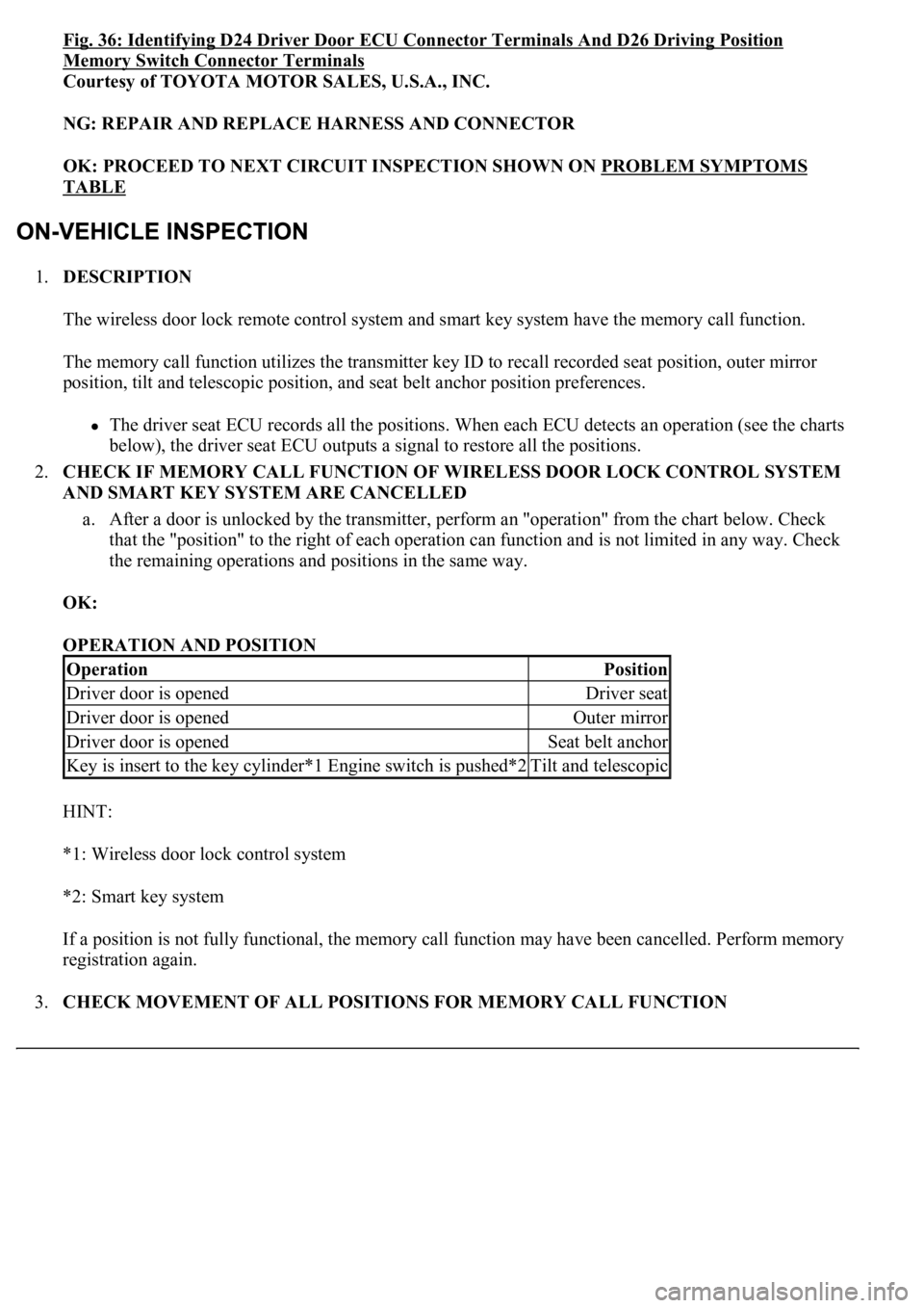
Fig. 36: Identifying D24 Driver Door ECU Connector Terminals And D26 Driving Position
Memory Switch Connector Terminals
Courtesy of TOYOTA MOTOR SALES, U.S.A., INC.
NG: REPAIR AND REPLACE HARNESS AND CONNECTOR
OK: PROCEED TO NEXT CIRCUIT INSPECTION SHOWN ON PROBLEM SYMPTOMS
TABLE
1.DESCRIPTION
The wireless door lock remote control system and smart key system have the memory call function.
The memory call function utilizes the transmitter key ID to recall recorded seat position, outer mirror
position, tilt and telescopic position, and seat belt anchor position preferences.
The driver seat ECU records all the positions. When each ECU detects an operation (see the charts
below), the driver seat ECU outputs a signal to restore all the positions.
2.CHECK IF MEMORY CALL FUNCTION OF WIRELESS DOOR LOCK CONTROL SYSTEM
AND SMART KEY SYSTEM ARE CANCELLED
a. After a door is unlocked by the transmitter, perform an "operation" from the chart below. Check
that the "position" to the right of each operation can function and is not limited in any way. Check
<0057004b004800030055004800500044004c0051004c0051004a0003005200530048005500440057004c00520051005600030044005100470003005300520056004c0057004c0052005100560003004c005100030057004b00480003005600440050004800
03005a0044005c001100030003[
OK:
OPERATION AND POSITION
HINT:
*1: Wireless door lock control system
*2: Smart key system
If a position is not fully functional, the memory call function may have been cancelled. Perform memory
registration again.
3.CHECK MOVEMENT OF ALL POSITIONS FOR MEMORY CALL FUNCTION
OperationPosition
Driver door is openedDriver seat
Driver door is openedOuter mirror
Driver door is openedSeat belt anchor
<002e0048005c0003004c00560003004c0051005600480055005700030057005200030057004b00480003004e0048005c00030046005c004f004c0051004700480055000d0014000300280051004a004c0051004800030056005a004c00570046004b000300
4c00560003005300580056004b00480047000d0015[Tilt and telescopic
Page 3966 of 4500
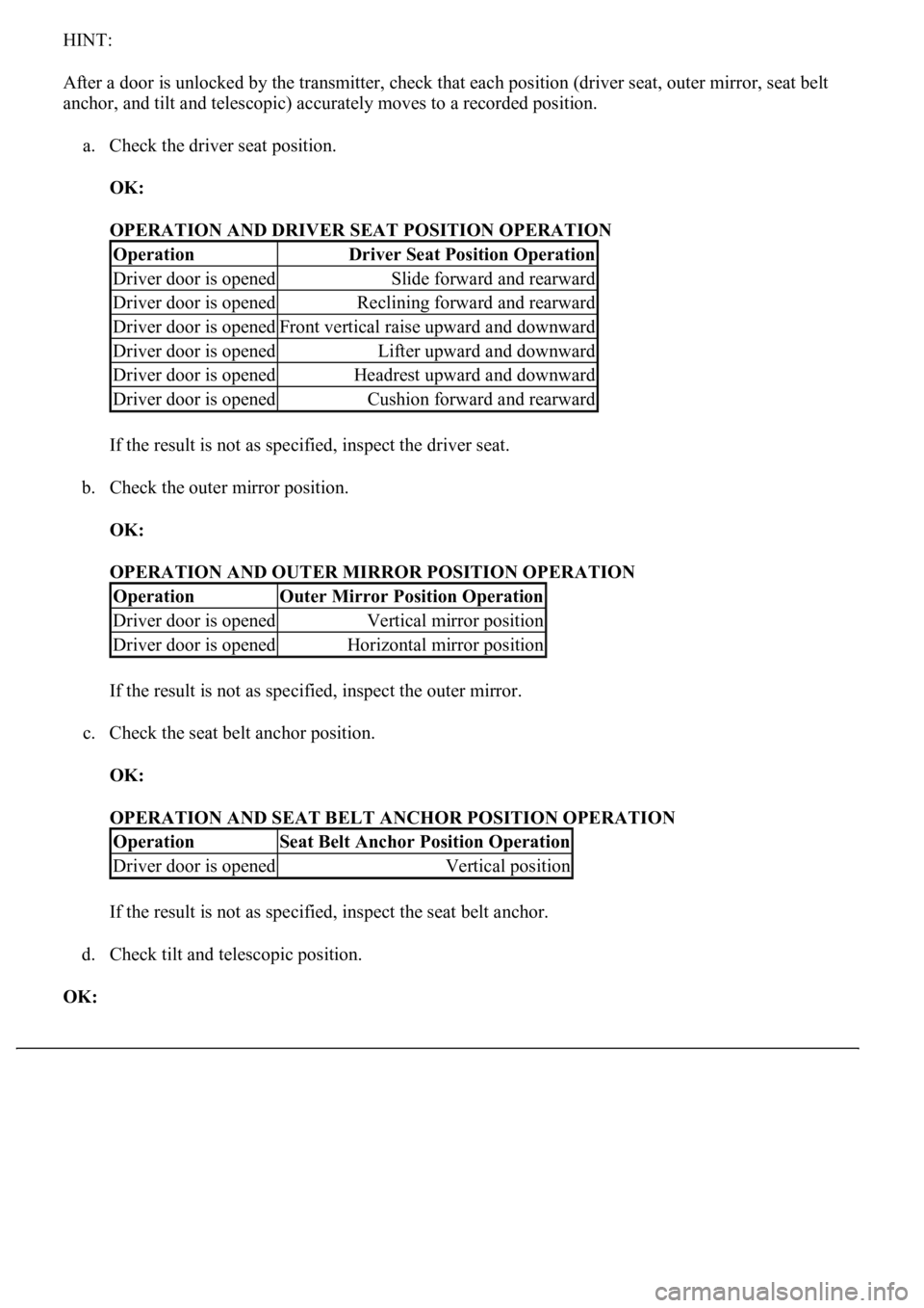
HINT:
After a door is unlocked by the transmitter, check that each position (driver seat, outer mirror, seat belt
anchor, and tilt and telescopic) accurately moves to a recorded position.
a. Check the driver seat position.
OK:
OPERATION AND DRIVER SEAT POSITION OPERATION
If the result is not as specified, inspect the driver seat.
b. Check the outer mirror position.
OK:
OPERATION AND OUTER MIRROR POSITION OPERATION
If the result is not as specified, inspect the outer mirror.
c. Check the seat belt anchor position.
OK:
OPERATION AND SEAT BELT ANCHOR POSITION OPERATION
If the result is not as specified, inspect the seat belt anchor.
d. Check tilt and telescopic position.
OK:
OperationDriver Seat Position Operation
Driver door is openedSlide forward and rearward
Driver door is openedReclining forward and rearward
Driver door is openedFront vertical raise upward and downward
Driver door is openedLifter upward and downward
Driver door is openedHeadrest upward and downward
Driver door is openedCushion forward and rearward
OperationOuter Mirror Position Operation
Driver door is openedVertical mirror position
Driver door is openedHorizontal mirror position
OperationSeat Belt Anchor Position Operation
Driver door is openedVertical position
Page 3967 of 4500
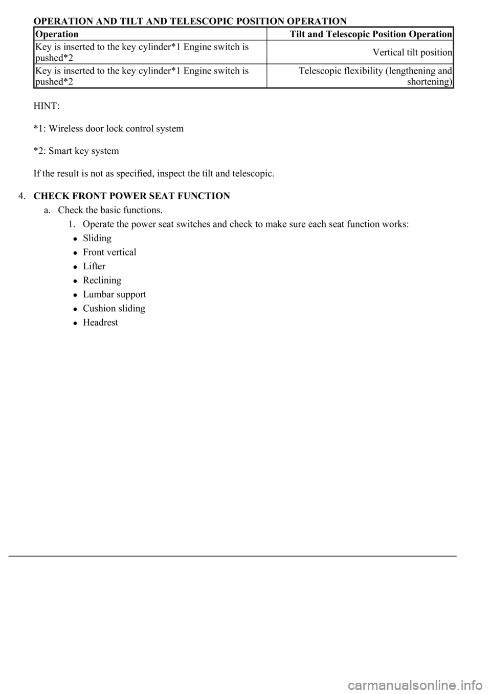
OPERATION AND TILT AND TELESCOPIC POSITION OPERATION
HINT:
*1: Wireless door lock control system
*2: Smart key system
If the result is not as specified, inspect the tilt and telescopic.
4.CHECK FRONT POWER SEAT FUNCTION
a. Check the basic functions.
1. Operate the power seat switches and check to make sure each seat function works:
Sliding
Front vertical
Lifter
Reclining
Lumbar support
Cushion sliding
Headrest
OperationTilt and Telescopic Position Operation
Key is inserted to the key cylinder*1 Engine switch is
pushed*2Vertical tilt position
Key is inserted to the key cylinder*1 Engine switch is
pushed*2Telescopic flexibility (lengthening and
shortening)
Page 3968 of 4500

Fig. 37: Identifying Front Power Seat Function
Courtesy of TOYOTA MOTOR SALES, U.S.A., INC.
5.CHECK POWER SEAT MOTOR ASSY
Page 3969 of 4500
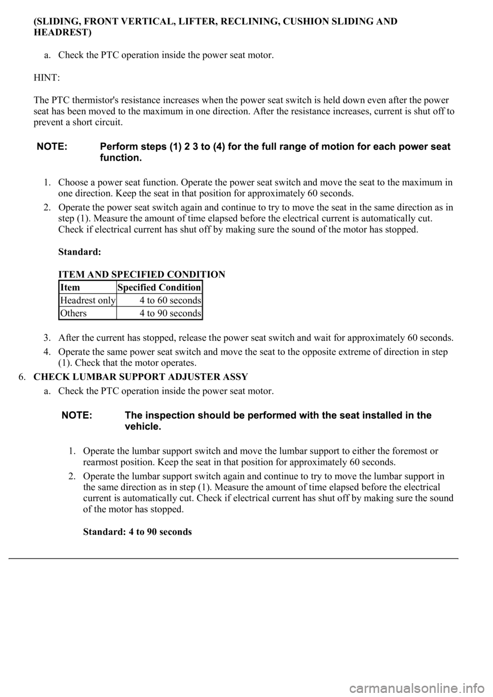
(SLIDING, FRONT VERTICAL, LIFTER, RECLINING, CUSHION SLIDING AND
HEADREST)
a. Check the PTC operation inside the power seat motor.
HINT:
The PTC thermistor's resistance increases when the power seat switch is held down even after the power
seat has been moved to the maximum in one direction. After the resistance increases, current is shut off to
prevent a short circuit.
1. Choose a power seat function. Operate the power seat switch and move the seat to the maximum in
one direction. Keep the seat in that position for approximately 60 seconds.
2. Operate the power seat switch again and continue to try to move the seat in the same direction as in
step (1). Measure the amount of time elapsed before the electrical current is automatically cut.
Check if electrical current has shut off by making sure the sound of the motor has stopped.
Standard:
ITEM AND SPECIFIED CONDITION
3. After the current has stopped, release the power seat switch and wait for approximately 60 seconds.
4. Operate the same power seat switch and move the seat to the opposite extreme of direction in step
(1). Check that the motor operates.
6.CHECK LUMBAR SUPPORT ADJUSTER ASSY
a. Check the PTC operation inside the power seat motor.
1. Operate the lumbar support switch and move the lumbar support to either the foremost or
rearmost position. Keep the seat in that position for approximately 60 seconds.
2. Operate the lumbar support switch again and continue to try to move the lumbar support in
the same direction as in step (1). Measure the amount of time elapsed before the electrical
current is automatically cut. Check if electrical current has shut off by making sure the sound
of the motor has stopped.
Standard: 4 to 90 seconds
ItemSpecified Condition
Headrest only4 to 60 seconds
Others4 to 90 seconds
Page 3970 of 4500
3. After the current has stopped, release the lumbar support switch and wait for approximately
60 seconds.
4. Operate the lumbar support switch and move the seat to the opposite extreme of direction in
step (1). Check that the motor operates.
7.CHECK MEMORY AND REACTIVATION FUNCTION
a. Turn the ignition switch ON and move the shift lever into the P position.
b. Check the M1 switch.
1. Using the seat switches, fully slide the seat forward, fully recline the seatback forward, and
fully raise the seat cushion and headrest.
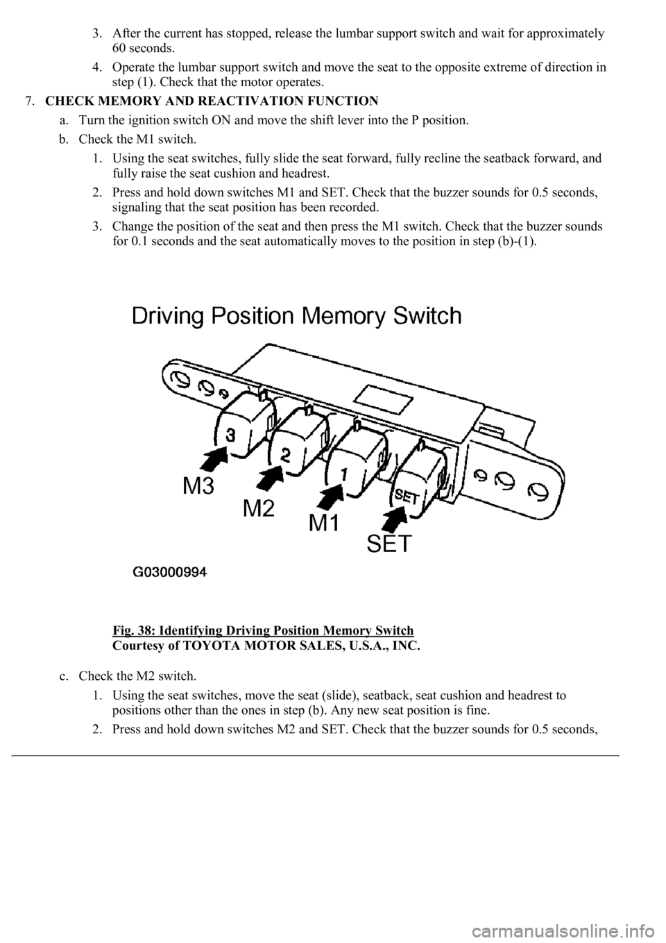
2. Press and hold down switches M1 and SET. Check that the buzzer sounds for 0.5 seconds,
signaling that the seat position has been recorded.
3. Change the position of the seat and then press the M1 switch. Check that the buzzer sounds
for 0.1 seconds and the seat automatically moves to the position in step (b)-(1).
<0029004c004a001100030016001b001d0003002c0047004800510057004c0049005c004c0051004a000300270055004c0059004c0051004a0003003300520056004c0057004c00520051000300300048005000520055005c00030036005a004c0057004600
4b[
Courtesy of TOYOTA MOTOR SALES, U.S.A., INC.
c. Check the M2 switch.
1. Using the seat switches, move the seat (slide), seatback, seat cushion and headrest to
positions other than the ones in step (b). Any new seat position is fine.
2. Press and hold down switches M2 and SET. Check that the buzzer sounds for 0.5 seconds,