LEXUS LS430 2003 Factory Repair Manual
Manufacturer: LEXUS, Model Year: 2003,
Model line: LS430,
Model: LEXUS LS430 2003
Pages: 4500, PDF Size: 87.45 MB
LEXUS LS430 2003 Factory Repair Manual
LS430 2003
LEXUS
LEXUS
https://www.carmanualsonline.info/img/36/57050/w960_57050-0.png
LEXUS LS430 2003 Factory Repair Manual
Trending: Soft hard, Expansion Valve, spare tire, audio, center console, air condition, compressor pressure
Page 3931 of 4500
Fig. 15: ECU Power Source Circuit (Driver Seat ECU) - Wiring Diagram
Courtesy of TOYOTA MOTOR SALES, U.S.A., INC.
Page 3932 of 4500
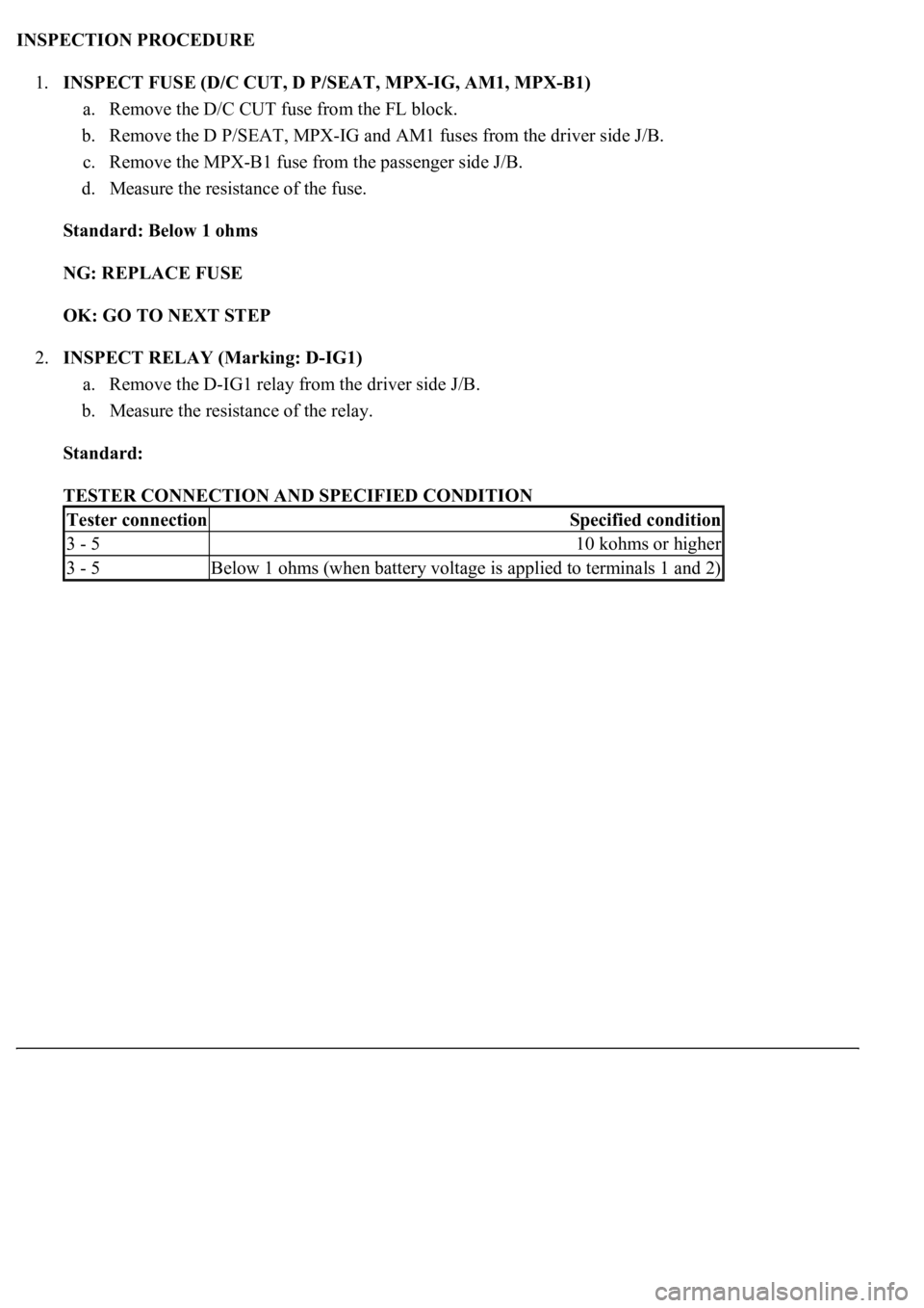
INSPECTION PROCEDURE
1.INSPECT FUSE (D/C CUT, D P/SEAT, MPX-IG, AM1, MPX-B1)
a. Remove the D/C CUT fuse from the FL block.
b. Remove the D P/SEAT, MPX-IG and AM1 fuses from the driver side J/B.
c. Remove the MPX-B1 fuse from the passenger side J/B.
d. Measure the resistance of the fuse.
Standard: Below 1 ohms
NG: REPLACE FUSE
OK: GO TO NEXT STEP
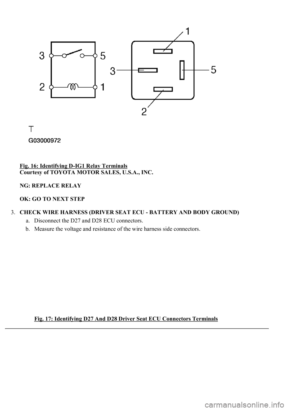
2.INSPECT RELAY (Marking: D-IG1)
a. Remove the D-IG1 relay from the driver side J/B.
b. Measure the resistance of the relay.
Standard:
TESTER CONNECTION AND SPECIFIED CONDITION
Tester connectionSpecified condition
3 - 510 kohms or higher
3 - 5Below 1 ohms (when battery voltage is applied to terminals 1 and 2)
Page 3933 of 4500
Fig. 16: Identifying D-IG1 Relay Terminals
Courtesy of TOYOTA MOTOR SALES, U.S.A., INC.
NG: REPLACE RELAY
OK: GO TO NEXT STEP
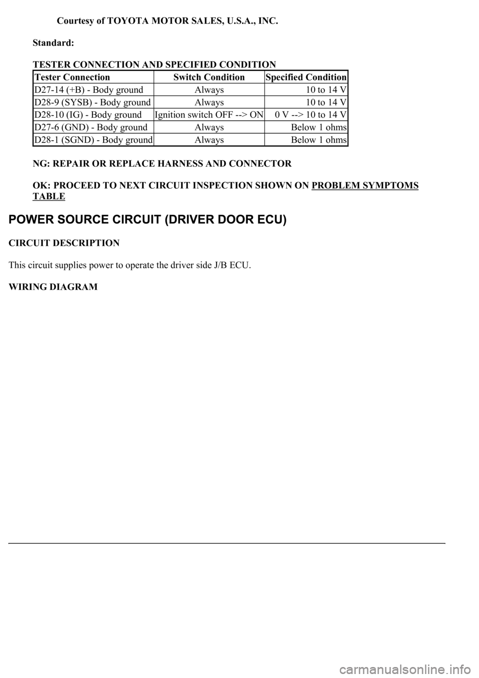
3.CHECK WIRE HARNESS (DRIVER SEAT ECU - BATTERY AND BODY GROUND)
a. Disconnect the D27 and D28 ECU connectors.
b. Measure the voltage and resistance of the wire harness side connectors.
Fig. 17: Identifying D27 And D28 Driver Seat ECU Connectors Terminals
Page 3934 of 4500
Courtesy of TOYOTA MOTOR SALES, U.S.A., INC.
Standard:
TESTER CONNECTION AND SPECIFIED CONDITION
NG: REPAIR OR REPLACE HARNESS AND CONNECTOR
OK: PROCEED TO NEXT CIRCUIT INSPECTION SHOWN ON PROBLEM SYMPTOMS
TABLE
CIRCUIT DESCRIPTION
This circuit supplies power to operate the driver side J/B ECU.
WIRING DIAGRAM
Tester ConnectionSwitch ConditionSpecified Condition
D27-14 (+B) - Body groundAlways10 to 14 V
D28-9 (SYSB) - Body groundAlways10 to 14 V
D28-10 (IG) - Body groundIgnition switch OFF --> ON0 V --> 10 to 14 V
D27-6 (GND) - Body groundAlwaysBelow 1 ohms
D28-1 (SGND) - Body groundAlwaysBelow 1 ohms
Page 3935 of 4500
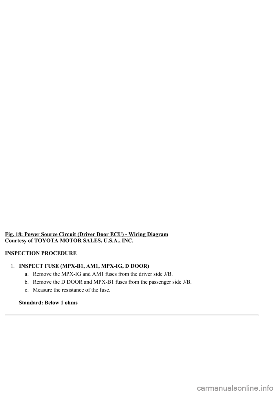
Fig. 18: Power Source Circuit (Driver Door ECU) - Wiring Diagram
Courtesy of TOYOTA MOTOR SALES, U.S.A., INC.
INSPECTION PROCEDURE
1.INSPECT FUSE (MPX-B1, AM1, MPX-IG, D DOOR)
a. Remove the MPX-IG and AM1 fuses from the driver side J/B.
b. Remove the D DOOR and MPX-B1 fuses from the passenger side J/B.
c. Measure the resistance of the fuse.
Standard: Below 1 ohms
Page 3936 of 4500
NG: REPLACE FUSE
OK: GO TO NEXT STEP
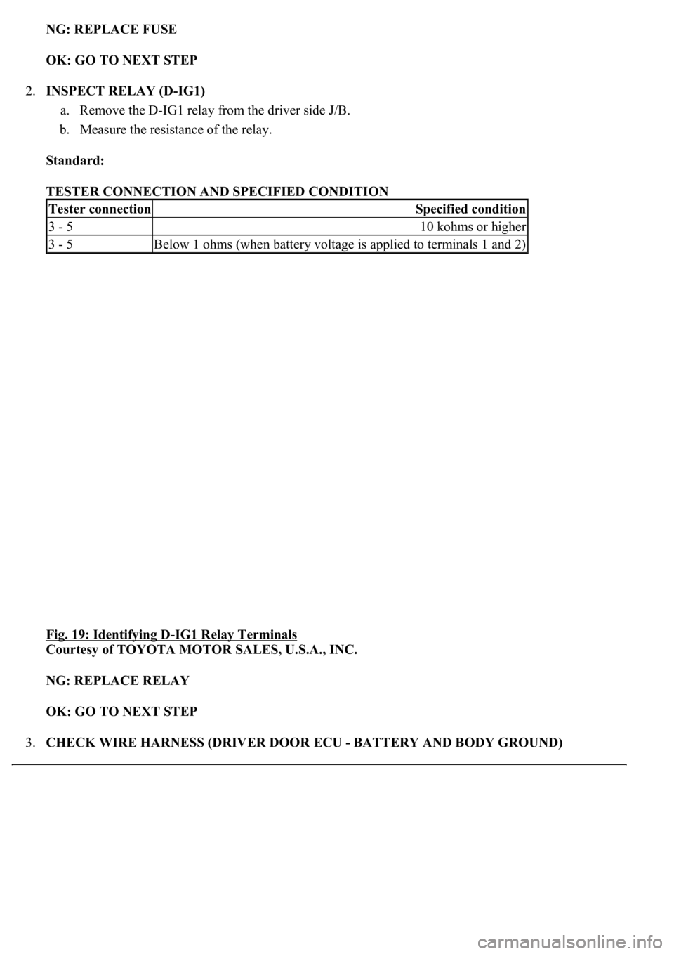
2.INSPECT RELAY (D-IG1)
a. Remove the D-IG1 relay from the driver side J/B.
b. Measure the resistance of the relay.
Standard:
TESTER CONNECTION AND SPECIFIED CONDITION
Fig. 19: Identifying D
-IG1 Relay Terminals
Courtesy of TOYOTA MOTOR SALES, U.S.A., INC.
NG: REPLACE RELAY
OK: GO TO NEXT STEP
3.CHECK WIRE HARNESS (DRIVER DOOR ECU - BATTERY AND BODY GROUND)
Tester connectionSpecified condition
3 - 510 kohms or higher
3 - 5Below 1 ohms (when battery voltage is applied to terminals 1 and 2)
Page 3937 of 4500
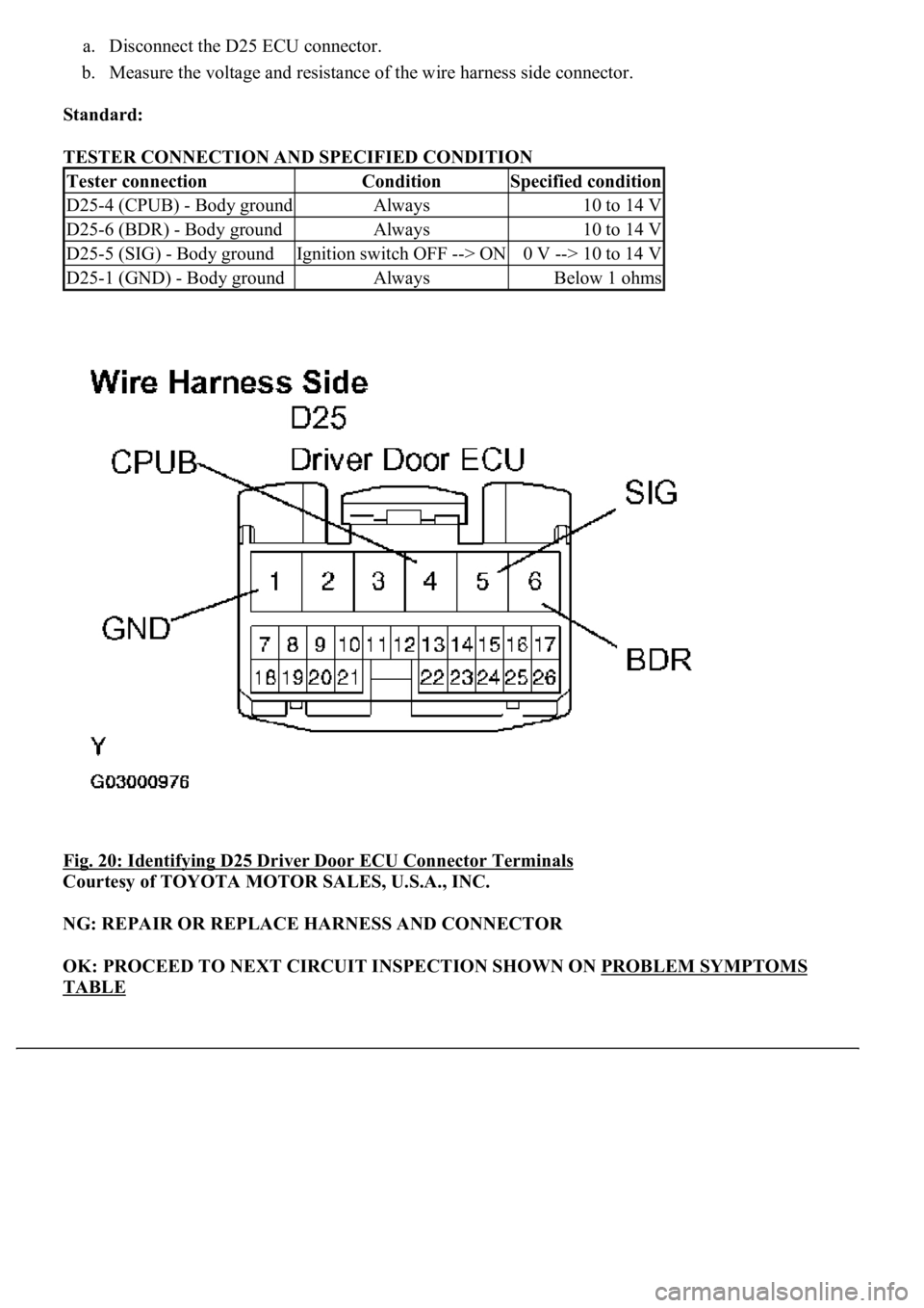
a. Disconnect the D25 ECU connector.
b. Measure the voltage and resistance of the wire harness side connector.
Standard:
TESTER CONNECTION AND SPECIFIED CONDITION
Fig. 20: Identifying D25 Driver Door ECU Connector Terminals
Courtesy of TOYOTA MOTOR SALES, U.S.A., INC.
NG: REPAIR OR REPLACE HARNESS AND CONNECTOR
OK: PROCEED TO NEXT CIRCUIT INSPECTION SHOWN ON PROBLEM SYMPTOMS
TABLE
Tester connectionConditionSpecified condition
D25-4 (CPUB) - Body groundAlways10 to 14 V
D25-6 (BDR) - Body groundAlways10 to 14 V
D25-5 (SIG) - Body groundIgnition switch OFF --> ON0 V --> 10 to 14 V
D25-1 (GND) - Body groundAlwaysBelow 1 ohms
Page 3938 of 4500
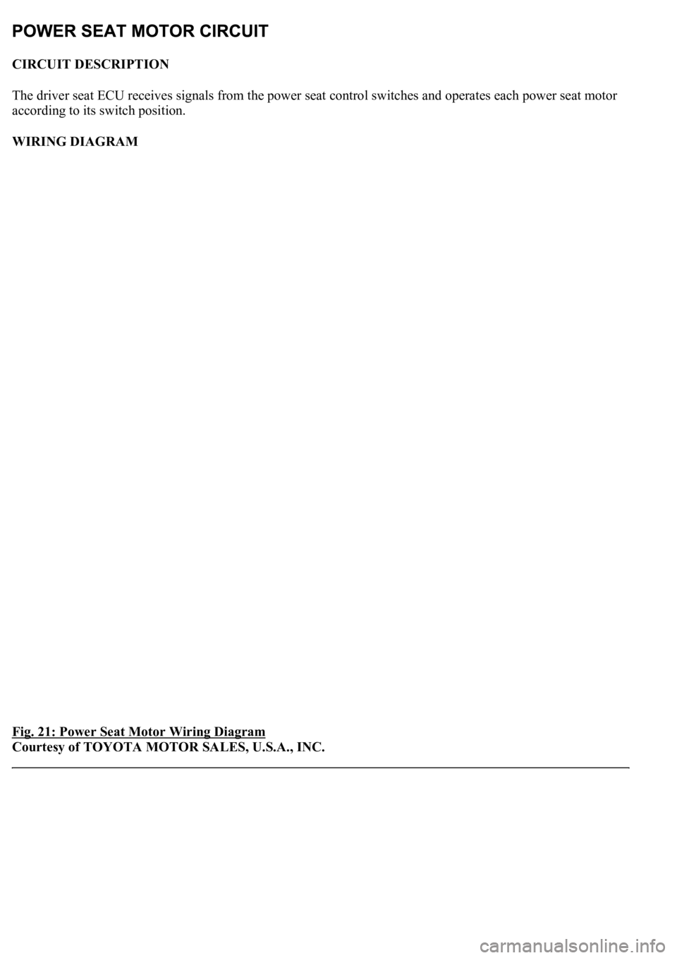
CIRCUIT DESCRIPTION
The driver seat ECU receives signals from the power seat control switches and operates each power seat motor
according to its switch position.
WIRING DIAGRAM
Fig. 21: Power Seat Motor Wiring Diagram
Courtesy of TOYOTA MOTOR SALES, U.S.A., INC.
Page 3939 of 4500
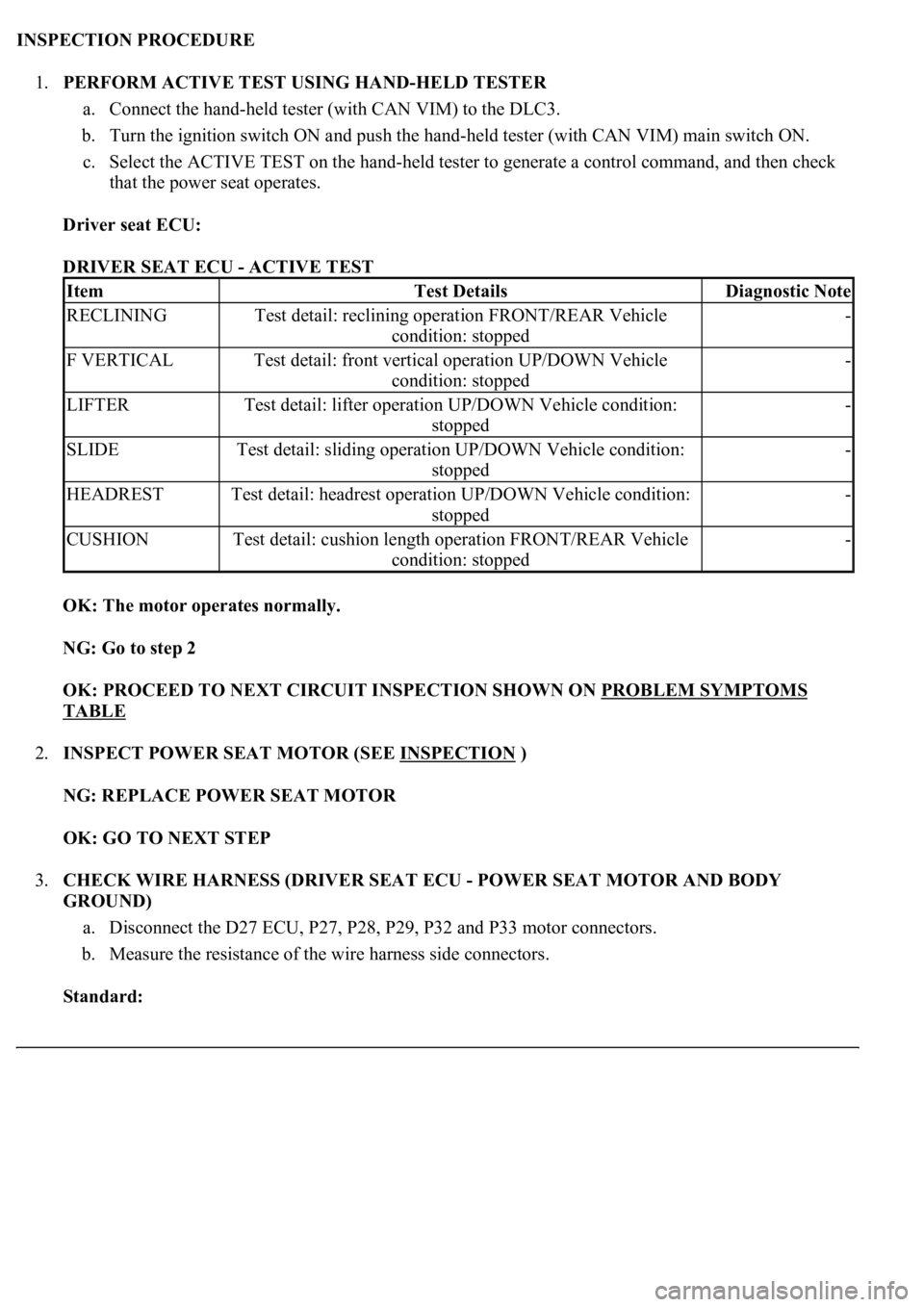
INSPECTION PROCEDURE
1.PERFORM ACTIVE TEST USING HAND-HELD TESTER
a. Connect the hand-held tester (with CAN VIM) to the DLC3.
b. Turn the ignition switch ON and push the hand-held tester (with CAN VIM) main switch ON.
c. Select the ACTIVE TEST on the hand-held tester to generate a control command, and then check
that the power seat operates.
Driver seat ECU:
DRIVER SEAT ECU - ACTIVE TEST
OK: The motor operates normally.
NG: Go to step 2
OK: PROCEED TO NEXT CIRCUIT INSPECTION SHOWN ON PROBLEM SYMPTOMS
TABLE
2.INSPECT POWER SEAT MOTOR (SEE INSPECTION
)
NG: REPLACE POWER SEAT MOTOR
OK: GO TO NEXT STEP
3.CHECK WIRE HARNESS (DRIVER SEAT ECU - POWER SEAT MOTOR AND BODY
GROUND)
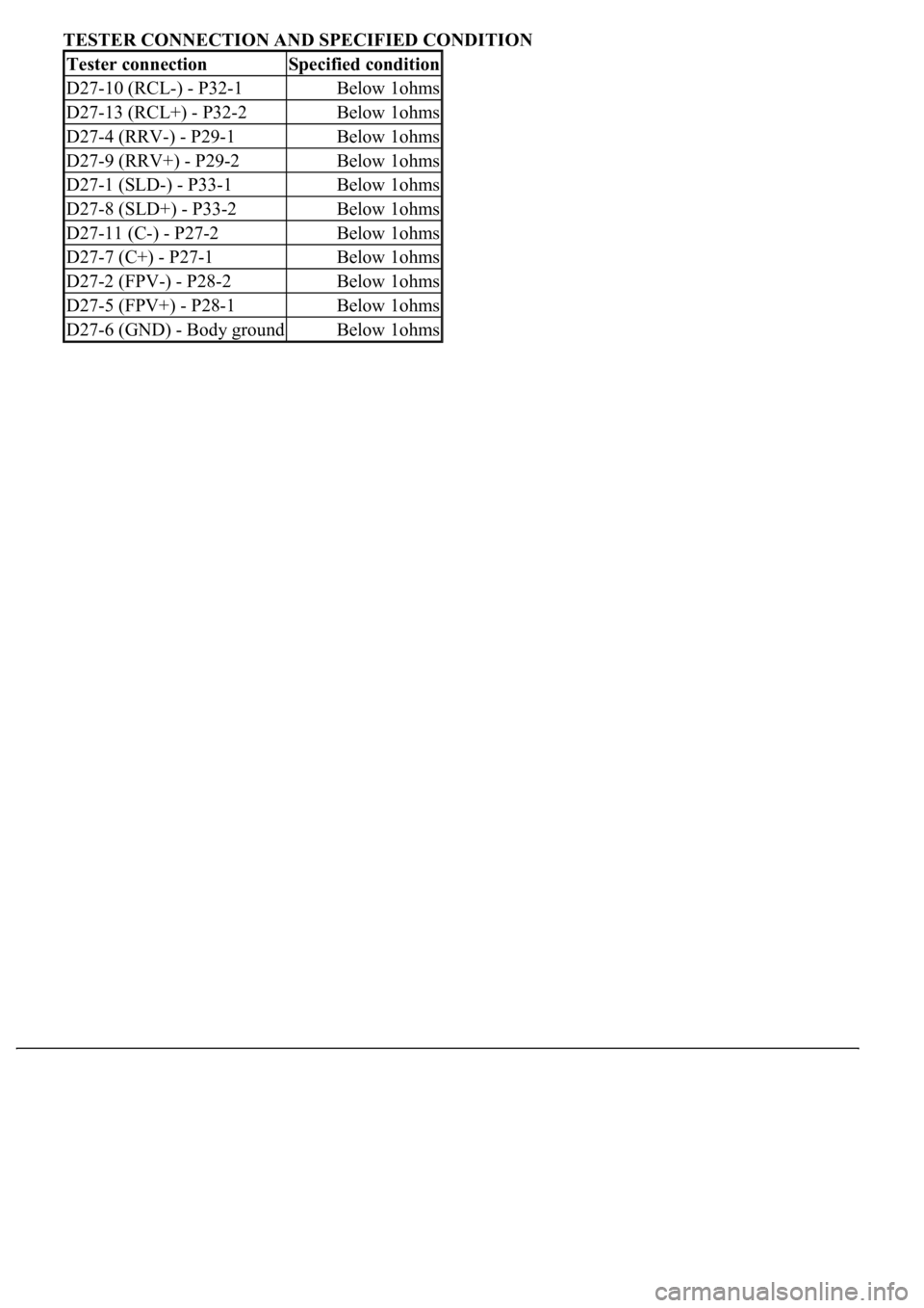
a. Disconnect the D27 ECU, P27, P28, P29, P32 and P33 motor connectors.
b. Measure the resistance of the wire harness side connectors.
Standard:
ItemTest DetailsDiagnostic Note
RECLININGTest detail: reclining operation FRONT/REAR Vehicle
condition: stopped-
F VERTICALTest detail: front vertical operation UP/DOWN Vehicle
condition: stopped-
LIFTERTest detail: lifter operation UP/DOWN Vehicle condition:
stopped-
SLIDETest detail: sliding operation UP/DOWN Vehicle condition:
stopped-
HEADRESTTest detail: headrest operation UP/DOWN Vehicle condition:
stopped-
CUSHIONTest detail: cushion length operation FRONT/REAR Vehicle
condition: stopped-
Page 3940 of 4500
TESTER CONNECTION AND SPECIFIED CONDITION
Tester connectionSpecified condition
D27-10 (RCL-) - P32-1Below 1ohms
D27-13 (RCL+) - P32-2Below 1ohms
D27-4 (RRV-) - P29-1Below 1ohms
D27-9 (RRV+) - P29-2Below 1ohms
D27-1 (SLD-) - P33-1Below 1ohms
D27-8 (SLD+) - P33-2Below 1ohms
D27-11 (C-) - P27-2Below 1ohms
D27-7 (C+) - P27-1Below 1ohms
D27-2 (FPV-) - P28-2Below 1ohms
D27-5 (FPV+) - P28-1Below 1ohms
D27-6 (GND) - Body groundBelow 1ohms
Trending: mirror, intake manifold inlet, clock, belt, steering interlock cable, C1752, coolant level

