LEXUS LS430 2003 Factory Repair Manual
Manufacturer: LEXUS, Model Year: 2003,
Model line: LS430,
Model: LEXUS LS430 2003
Pages: 4500, PDF Size: 87.45 MB
LEXUS LS430 2003 Factory Repair Manual
LS430 2003
LEXUS
LEXUS
https://www.carmanualsonline.info/img/36/57050/w960_57050-0.png
LEXUS LS430 2003 Factory Repair Manual
Trending: torque, idler tensioner pulley, fuel pressure, dlc3, wiring diagram, fuse diagram, seats
Page 3941 of 4500
Page 3942 of 4500
Fig. 22: Identifying D27 Driver Seat ECU Connector Terminals And Power Seat Motor Connector
Terminals
Courtesy of TOYOTA MOTOR SALES, U.S.A., INC.
NG: REPAIR OR REPLACE WIRE HARNESS AND CONNECTOR
OK: PROCEED TO NEXT CIRCUIT INSPECTION SHOWN ON PROBLEM SYMPTOMS
TABLE
CIRCUIT DESCRIPTION
The position sensor detects seat movement and sends pulse signals to the driver seat ECU for use with the
memory function.
The ECU records the number of pulses relative to a previously recorded seat position and uses this data to
return the seat to that position.
If a malfunction occurs in a position sensor and seat movement does not result in pulse signals being input into
the ECU, the memory function is deactivated.
WIRING DIAGRAM
Page 3943 of 4500
Fig. 23: Position Sensor Wiring Diagram
Courtesy of TOYOTA MOTOR SALES, U.S.A., INC.
Page 3944 of 4500
INSPECTION PROCEDURE
1.READ VALUE OF HAND-HELD TESTER
a. Connect the hand-held tester (with CAN VIM) to the DLC3.
b. Turn the ignition switch ON and press the hand-held tester main switch ON.
c. Select the items below in the DATA LIST, and read the hand-held tester's screen.
d. Watch the hand-held tester screen while adjusting the seat with the power seat control switches.
Check that the position sensor value changes.
e. Watch the hand-held tester screen while adjusting the seat with the power seat control switches.
Check that the motor status changes from STANDBY to MOVING.
HINT:
When the seat is at an extreme position (for example, seatback position fully forward or sliding position
fully rearward) and the power seat control switch is held down, the motor status should read LOCK.
When the switch is released, the motor status should change to STANDBY.
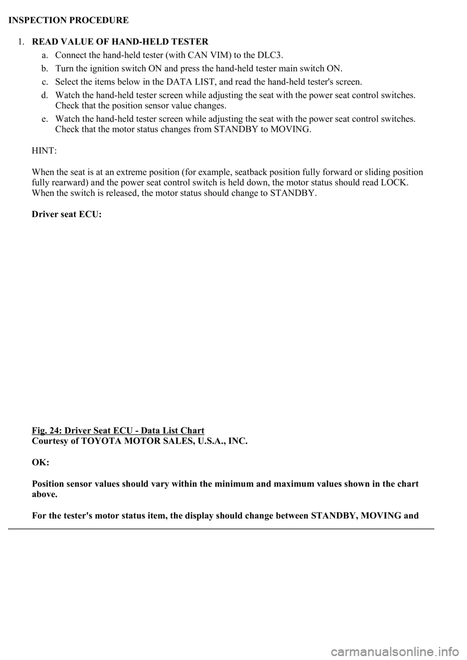
Driver seat ECU:
Fig. 24: Driver Seat ECU
- Data List Chart
Courtesy of TOYOTA MOTOR SALES, U.S.A., INC.
OK:
Position sensor values should vary within the minimum and maximum values shown in the chart
above.
For the tester's motor status item, the display should change between STANDBY, MOVING and
Page 3945 of 4500
LOCK according to the chart above.
NG: Go to step 2
OK: PROCEED TO NEXT CIRCUIT INSPECTION SHOWN ON PROBLEM SYMPTOMS
TABLE
2.CHECK WIRE HARNESS (DRIVER SEAT ECU - POWER SEAT SENSOR AND BODY
GROUND)
a. Disconnect the D27 and D28 ECU connectors.
b. Disconnect the P40, P41, P42, P43, P44 and P45 sensor connectors.
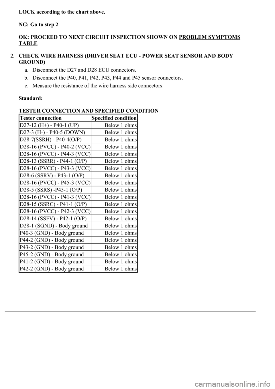
c. Measure the resistance of the wire harness side connectors.
Standard:
TESTER CONNECTION AND SPECIFIED CONDITION
Tester connectionSpecified condition
D27-12 (H+) - P40-1 (UP)Below 1 ohms
D27-3 (H-) - P40-5 (DOWN)Below 1 ohms
D28-7(SSRH) - P40-4(O/P)Below 1 ohms
D28-16 (PVCC) - P40-2 (VCC)Below 1 ohms
D28-16 (PVCC) - P44-3 (VCC)Below 1 ohms
D28-13 (SSRR) - P44-1 (O/P)Below 1 ohms
D28-16 (PVCC) - P43-3 (VCC)Below 1 ohms
D28-6 (SSRV) - P43-1 (O/P)Below 1 ohms
D28-16 (PVCC) - P45-3 (VCC)Below 1 ohms
D28-5 (SSRS) -P45-1 (O/P)Below 1 ohms
D28-16 (PVCC) - P41-3 (VCC)Below 1 ohms
D28-15 (SSRC) - P41-1 (O/P)Below 1 ohms
D28-16 (PVCC) - P42-3 (VCC)Below 1 ohms
D28-14 (SSFV) - P42-1 (O/P)Below 1 ohms
D28-1 (SGND) - Body groundBelow 1 ohms
P40-3 (GND) - Body groundBelow 1 ohms
P44-2 (GND) - Body groundBelow 1 ohms
P43-2 (GND) - Body groundBelow 1 ohms
P45-2 (GND) - Body groundBelow 1 ohms
P41-2 (GND) - Body groundBelow 1 ohms
P42-2 (GND) - Body groundBelow 1 ohms
Page 3946 of 4500
Fig. 25: Identifying D27, D28 Driver Seat ECU Connector Terminals And Power Seat Sensor
Connector Terminals
Courtesy of TOYOTA MOTOR SALES, U.S.A., INC.
NG: REPAIR OR REPLACE HARNESS AND CONNECTOR
Page 3947 of 4500
OK: GO TO NEXT STEP
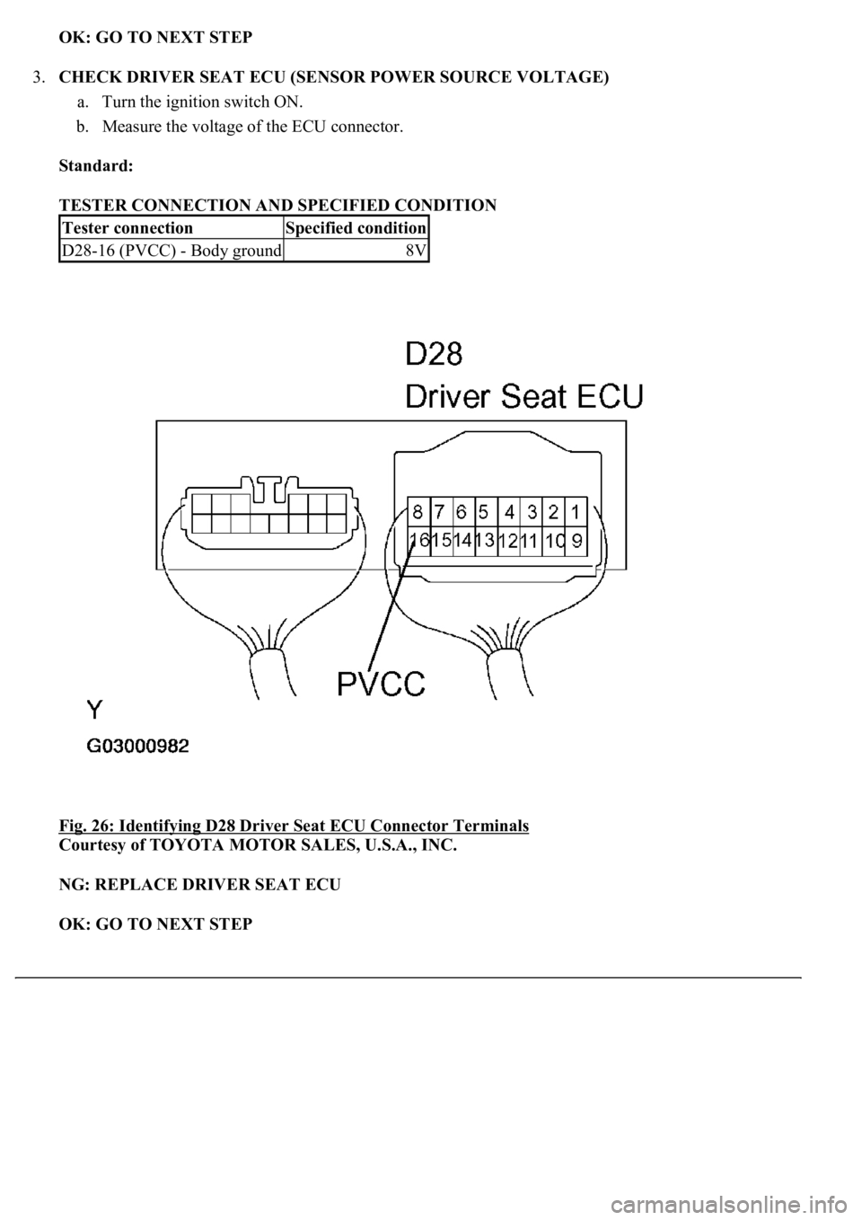
3.CHECK DRIVER SEAT ECU (SENSOR POWER SOURCE VOLTAGE)
a. Turn the ignition switch ON.
b. Measure the voltage of the ECU connector.
Standard:
TESTER CONNECTION AND SPECIFIED CONDITION
Fig. 26: Identifying D28 Driver Seat ECU Connector Terminals
Courtesy of TOYOTA MOTOR SALES, U.S.A., INC.
NG: REPLACE DRIVER SEAT ECU
OK: GO TO NEXT STEP
Tester connectionSpecified condition
D28-16 (PVCC) - Body ground8V
Page 3948 of 4500
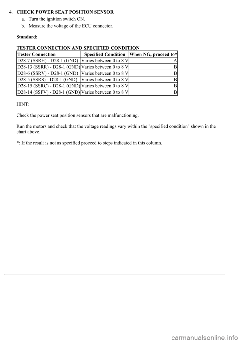
4.CHECK POWER SEAT POSITION SENSOR
a. Turn the ignition switch ON.
b. Measure the voltage of the ECU connector.
Standard:
TESTER CONNECTION AND SPECIFIED CONDITION
HINT:
Check the power seat position sensors that are malfunctioning.
Run the motors and check that the voltage readings vary within the "specified condition" shown in the
chart above.
*: If the result is not as specified proceed to steps indicated in this column.
Tester ConnectionSpecified ConditionWhen NG, proceed to*
D28-7 (SSRH) - D28-1 (GND)Varies between 0 to 8 VA
D28-13 (SSRR) - D28-1 (GND)Varies between 0 to 8 VB
D28-6 (SSRV) - D28-1 (GND)Varies between 0 to 8 VB
D28-5 (SSRS) - D28-1 (GND)Varies between 0 to 8 VB
D28-15 (SSRC) - D28-1 (GND)Varies between 0 to 8 VB
D28-14 (SSFV) - D28-1 (GND)Varies between 0 to 8 VB
Page 3949 of 4500
Fig. 27: Identifying D28 Driver Seat ECU Connector Terminals
Courtesy of TOYOTA MOTOR SALES, U.S.A., INC.
A: REPLACE FRONT SEAT HEADREST ADJUSTER
B: REPLACE FRONT POWER SEAT ADJUSTER
OK: PROCEED TO NEXT CIRCUIT INSPECTION SHOWN ON PROBLEM SYMPTOMS
TABLE
CIRCUIT DESCRIPTION
Pressing the lumbar switch activates the lumbar support motor.
Because the lumbar support switch is not connected to the driver seat ECU, pressing this switch does not
operate ECU operations such as the memory function.
WIRING DIAGRAM
Page 3950 of 4500
Fig. 28: Lumbar Support Switch Wiring Diagram
Courtesy of TOYOTA MOTOR SALES, U.S.A., INC.
INSPECTION PROCEDURE
1.INSPECT LUMBAR SUPPORT SWITCH
a. Remove the lumbar support switch.
b. Measure the resistance.
Standard:
Upper side control
TESTER CONNECTION AND SPECIFIED CONDITION
Trending: brake pads, radio antenna, oil reset, fuse box location, Identifying ac, oil filter, traction control

