LEXUS LS430 2003 Factory Repair Manual
Manufacturer: LEXUS, Model Year: 2003,
Model line: LS430,
Model: LEXUS LS430 2003
Pages: 4500, PDF Size: 87.45 MB
LEXUS LS430 2003 Factory Repair Manual
LS430 2003
LEXUS
LEXUS
https://www.carmanualsonline.info/img/36/57050/w960_57050-0.png
LEXUS LS430 2003 Factory Repair Manual
Trending: light, suspension, oil dipstick, oil pressure, Identifying ac, oil change, mirror
Page 4001 of 4500
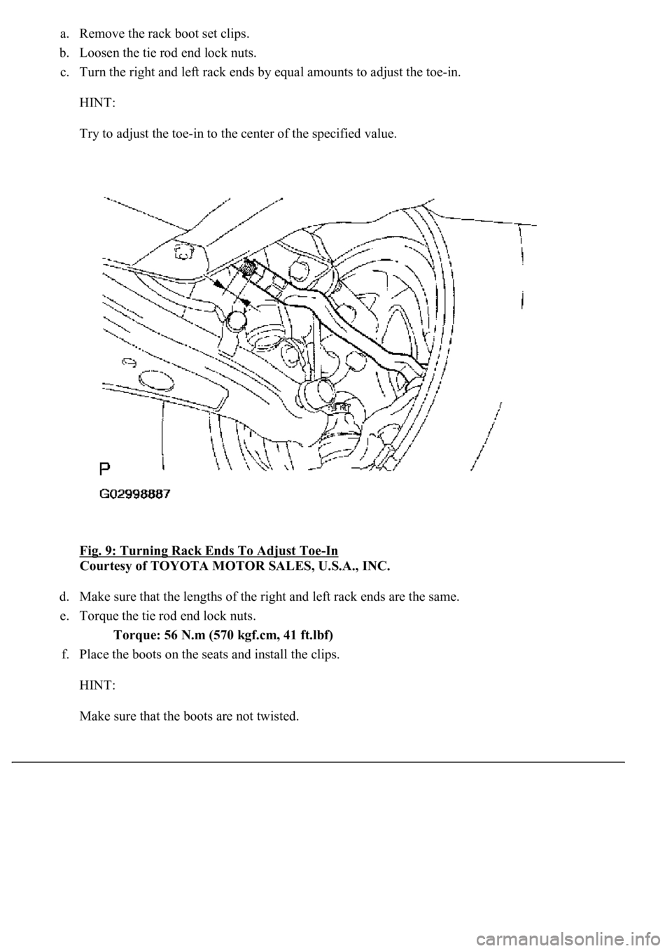
a. Remove the rack boot set clips.
b. Loosen the tie rod end lock nuts.
c. Turn the right and left rack ends by equal amounts to adjust the toe-in.
HINT:
Try to adjust the toe-in to the center of the specified value.
Fig. 9: Turning Rack Ends To Adjust Toe
-In
Courtesy of TOYOTA MOTOR SALES, U.S.A., INC.
d. Make sure that the lengths of the right and left rack ends are the same.
e. Torque the tie rod end lock nuts.
Torque: 56 N.m (570 kgf.cm, 41 ft.lbf)
f. Place the boots on the seats and install the clips.
HINT:
Make sure that the boots are not twisted.
Page 4002 of 4500
g. Perform the zero point calibration of yaw rate and deceleration sensor (see CALIBRATION ).
5.INSPECT WHEEL ANGLE
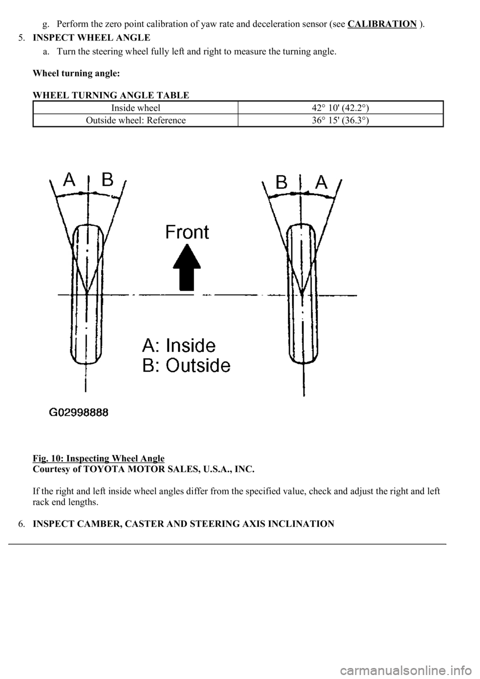
a. Turn the steering wheel fully left and right to measure the turning angle.
Wheel turning angle:
WHEEL TURNING ANGLE TABLE
Fig. 10: Inspecting Wheel Angle
Courtesy of TOYOTA MOTOR SALES, U.S.A., INC.
If the right and left inside wheel angles differ from the specified value, check and adjust the right and left
rack end lengths.
6.INSPECT CAMBER, CASTER AND STEERING AXIS INCLINATION
Inside wheel42° 10' (42.2°)
Outside wheel: Reference36° 15' (36.3°)
Page 4003 of 4500
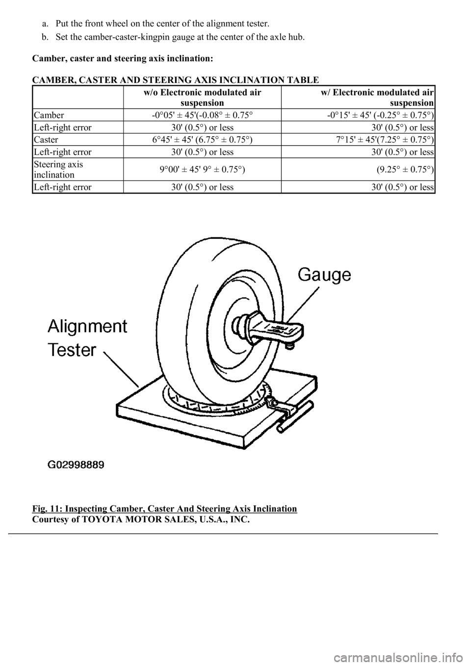
a. Put the front wheel on the center of the alignment tester.
b. Set the camber-caster-kingpin gauge at the center of the axle hub.
Camber, caster and steering axis inclination:
CAMBER, CASTER AND STEERING AXIS INCLINATION TABLE
Fig. 11: Inspecting Camber, Caster And Steering Axis Inclination
Courtesy of TOYOTA MOTOR SALES, U.S.A., INC.
w/o Electronic modulated air
suspensionw/ Electronic modulated air
suspension
Camber-0°05' ± 45'(-0.08° ± 0.75°-0°15' ± 45' (-0.25° ± 0.75°)
Left-right error30' (0.5°) or less30' (0.5°) or less
Caster6°45' ± 45' (6.75° ± 0.75°)7°15' ± 45'(7.25° ± 0.75°)
Left-right error30' (0.5°) or less30' (0.5°) or less
Steering axis
inclination9°00' ± 45' 9° ± 0.75°)(9.25° ± 0.75°)
Left-right error30' (0.5°) or less30' (0.5°) or less
Page 4004 of 4500
7.ADJUST CAMBER
HINT:
After adjusting the camber, inspect the caster and toe-in.
Try to adjust the camber to the center value.
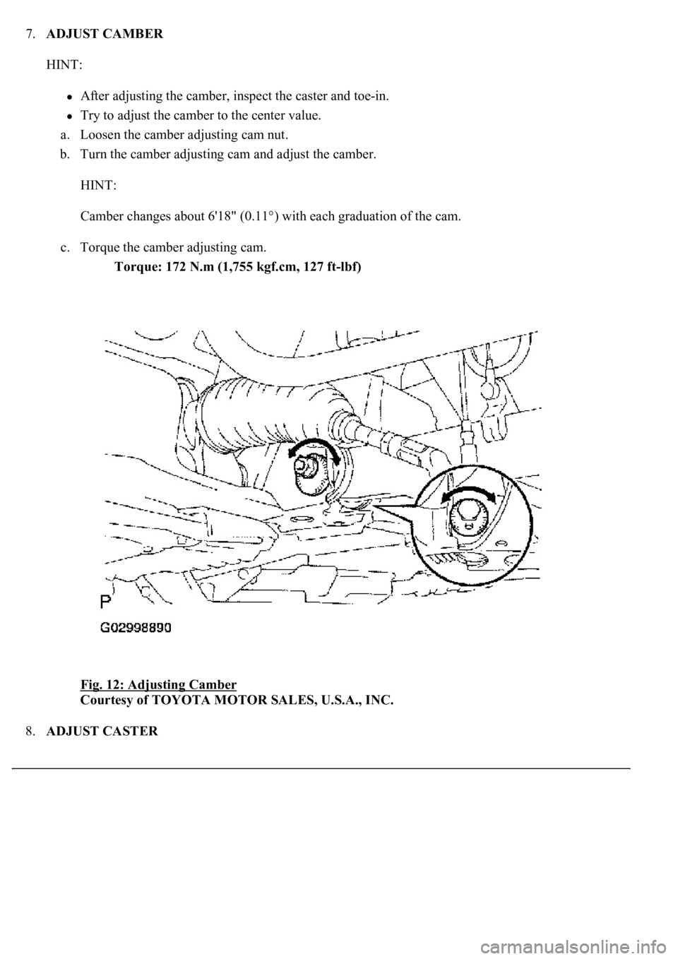
a. Loosen the camber adjusting cam nut.
b. Turn the camber adjusting cam and adjust the camber.
HINT:
Camber changes about 6'18" (0.11°) with each graduation of the cam.
c. Torque the camber adjusting cam.
Torque: 172 N.m (1,755 kgf.cm, 127 ft-lbf)
Fig. 12: Adjusting Camber
Courtesy of TOYOTA MOTOR SALES, U.S.A., INC.
8.ADJUST CASTER
Page 4005 of 4500
HINT:
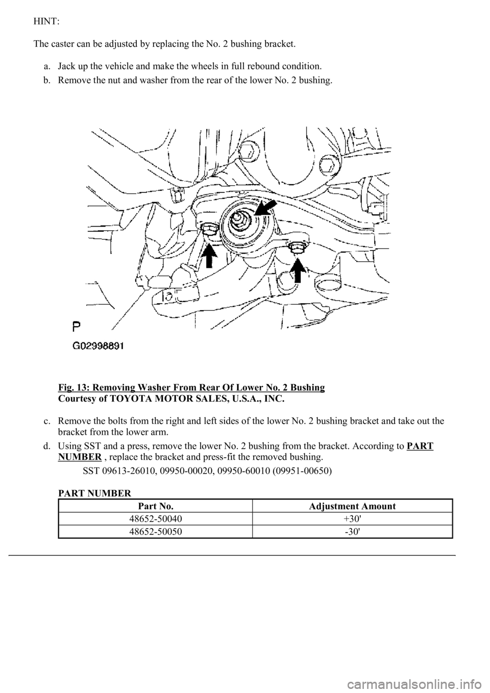
The caster can be adjusted by replacing the No. 2 bushing bracket.
a. Jack up the vehicle and make the wheels in full rebound condition.
b. Remove the nut and washer from the rear of the lower No. 2 bushing.
<0029004c004a0011000300140016001d000300350048005000520059004c0051004a0003003a00440056004b0048005500030029005500520050000300350048004400550003003200490003002f0052005a00480055000300310052001100030015000300
2500580056004b004c0051004a[
Courtesy of TOYOTA MOTOR SALES, U.S.A., INC.
c. Remove the bolts from the right and left sides of the lower No. 2 bushing bracket and take out the
bracket from the lower arm.
d. Using SST and a press, remove the lower No. 2 bushing from the bracket. According to PART
NUMBER<0003000f0003005500480053004f00440046004800030057004b004800030045005500440046004e00480057000300440051004700030053005500480056005600100049004c005700030057004b0048000300550048005000520059004800470003004500
580056004b004c0051004a00110003[
<00360036003700030013001c001900140016001000150019001300140013000f00030013001c001c00180013001000130013001300150013000f00030013001c001c001800130010001900130013001400130003000b0013001c001c001800140010001300
13001900180013000c00030003[
PART NUMBER
Part No.Adjustment Amount
48652-50040+30'
48652-50050-30'
Page 4006 of 4500
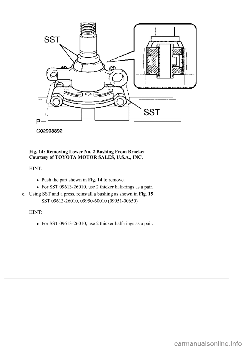
Fig. 14: Removing Lower No. 2 Bushing From Bracket
Courtesy of TOYOTA MOTOR SALES, U.S.A., INC.
HINT:
Push the part shown in Fig. 14 to remove.
For SST 09613-26010, use 2 thicker half-rings as a pair.
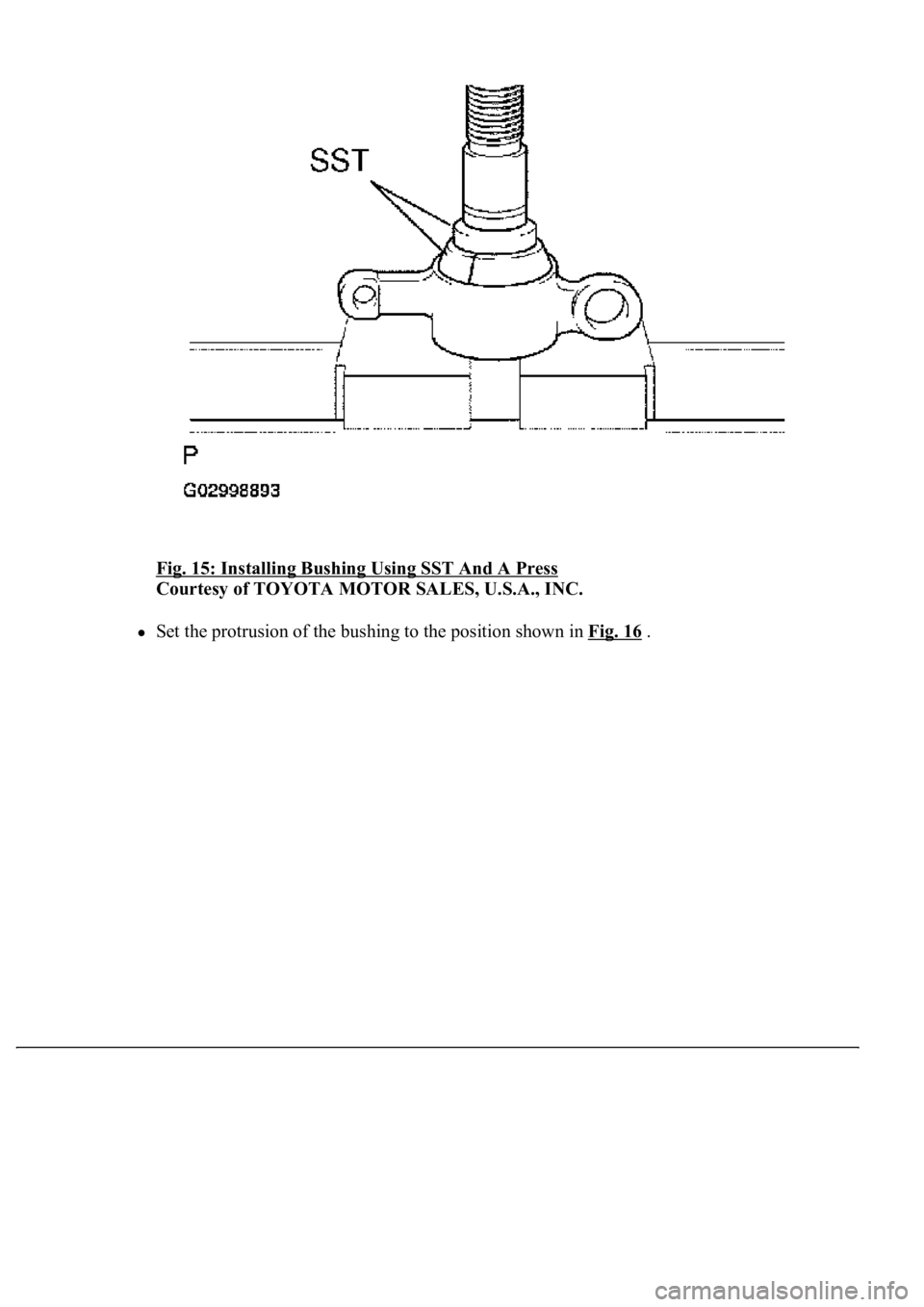
e. Using SST and a press, reinstall a bushing as shown in Fig. 15
.
SST 09613-26010, 09950-60010 (09951-00650)
HINT:
For SST 09613-26010, use 2 thicker half-rings as a pair.
Page 4007 of 4500
Fig. 15: Installing Bushing Using SST And A Press
Courtesy of TOYOTA MOTOR SALES, U.S.A., INC.
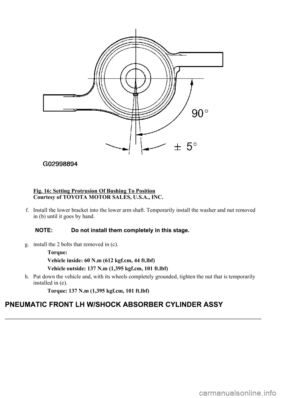
Set the protrusion of the bushing to the position shown in Fig. 16 .
Page 4008 of 4500
Fig. 16: Setting Protrusion Of Bushing To Position
Courtesy of TOYOTA MOTOR SALES, U.S.A., INC.
f. Install the lower bracket into the lower arm shaft. Temporarily install the washer and nut removed
in (b) until it goes by hand.
g. install the 2 bolts that removed in (c).
Torque:
Vehicle inside: 60 N.m (612 kgf.cm, 44 ft.lbf)
Vehicle outside: 137 N.m (1,395 kgf.cm, 101 ft.lbf)
h. Put down the vehicle and, with its wheels completely grounded, tighten the nut that is temporarily
installed in (e).
Torque: 137 N.m (1,395 kgf.cm, 101 ft.lbf)
Page 4009 of 4500
REPLACEMENT
HINT:
Use the same procedures for the RH side and LH side.
The procedures listed below are for the LH side.
1.REMOVE FRONT WHEELS
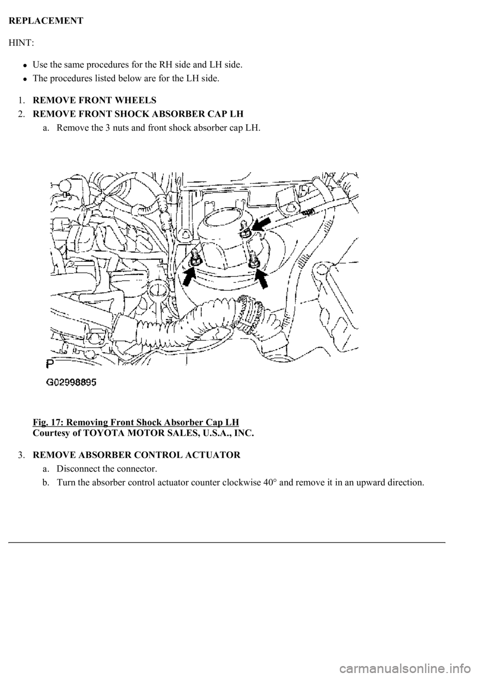
2.REMOVE FRONT SHOCK ABSORBER CAP LH
a. Remove the 3 nuts and front shock absorber cap LH.
Fig. 17: Removing Front Shock Absorber Cap LH
Courtesy of TOYOTA MOTOR SALES, U.S.A., INC.
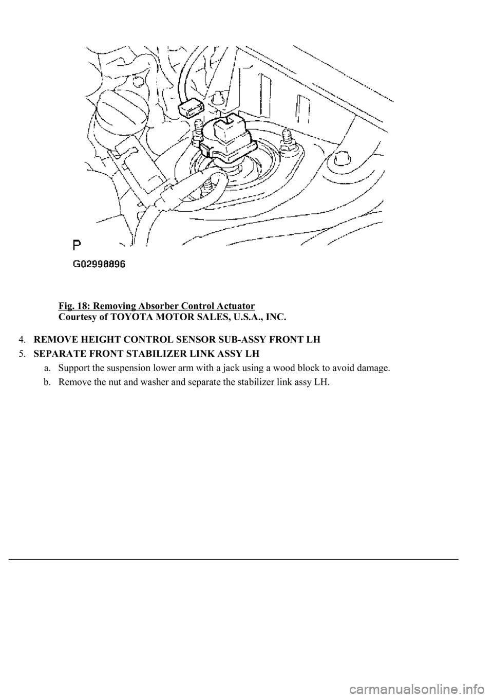
3.REMOVE ABSORBER CONTROL ACTUATOR
a. Disconnect the connector.
b. Turn the absorber control actuator counter clockwise 40° and remove it in an upward direction.
Page 4010 of 4500
Fig. 18: Removing Absorber Control Actuator
Courtesy of TOYOTA MOTOR SALES, U.S.A., INC.
4.REMOVE HEIGHT CONTROL SENSOR SUB-ASSY FRONT LH
5.SEPARATE FRONT STABILIZER LINK ASSY LH
a. Support the suspension lower arm with a jack using a wood block to avoid damage.
b. Remove the nut and washer and separate the stabilizer link assy LH.
Trending: navigation system, steering wheel adjustment, zero point calibration, coolant temperature, Ecm, height adjustment, water pump
