LEXUS LS430 2003 Factory Repair Manual
Manufacturer: LEXUS, Model Year: 2003,
Model line: LS430,
Model: LEXUS LS430 2003
Pages: 4500, PDF Size: 87.45 MB
LEXUS LS430 2003 Factory Repair Manual
LS430 2003
LEXUS
LEXUS
https://www.carmanualsonline.info/img/36/57050/w960_57050-0.png
LEXUS LS430 2003 Factory Repair Manual
Trending: trip computer, c1336, Air Conditioning Compressor, wheel, Rear suspension, height adjustment, airbag off
Page 4091 of 4500
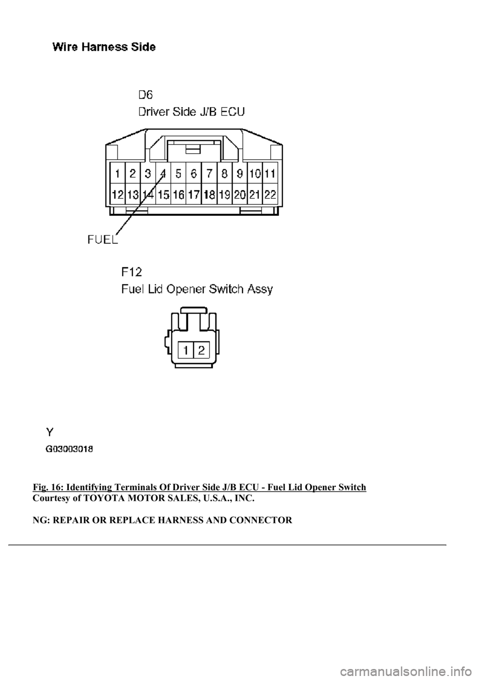
Fig. 16: Identifying Terminals Of Driver Side J/B ECU - Fuel Lid Opener Switch
Courtesy of TOYOTA MOTOR SALES, U.S.A., INC.
NG: REPAIR OR REPLACE HARNESS AND CONNECTOR
Page 4092 of 4500
OK: PROCEED TO NEXT CIRCUIT INSPECTION SHOWN ON PROBLEM SYMPTOMS
TABLE
CIRCUIT DESCRIPTION
The circuit opens the fuel lid when the ECU sends signals to the fuel lid opener switch.
WIRING DIAGRAM
Fig. 17: Wiring Diagram
- Fuel Lid Opener Motor Circuit
Courtesy of TOYOTA MOTOR SALES, U.S.A., INC.
INSPECTION PROCEDURE
1.PERFORM ACTIVE TEST (FUEL LID OPEN)
a. Select the ACTIVE TEST, use the hand-held tester to generate a control command, and then check
the fuel lid opener motor.
Luggage room J/B ECU:
LUGGAGE ROOM J/B ECU
Page 4093 of 4500
OK: Fuel lid opener is opened.
NG: Go to step 2
OK: PROCEED TO NEXT CIRCUIT INSPECTION SHOWN ON PROBLEM SYMPTOMS
TABLE
2.INSPECT FUSE (FUEL OPN)
a. Remove the FUEL OPN fuse from the luggage room J/B.
b. Measure the resistance.
Standard: Below 1 ohms
NG: REPLACE FUSE
OK: GO TO NEXT STEP
3.INSPECT FUEL LID OPENER MOTOR ASSY
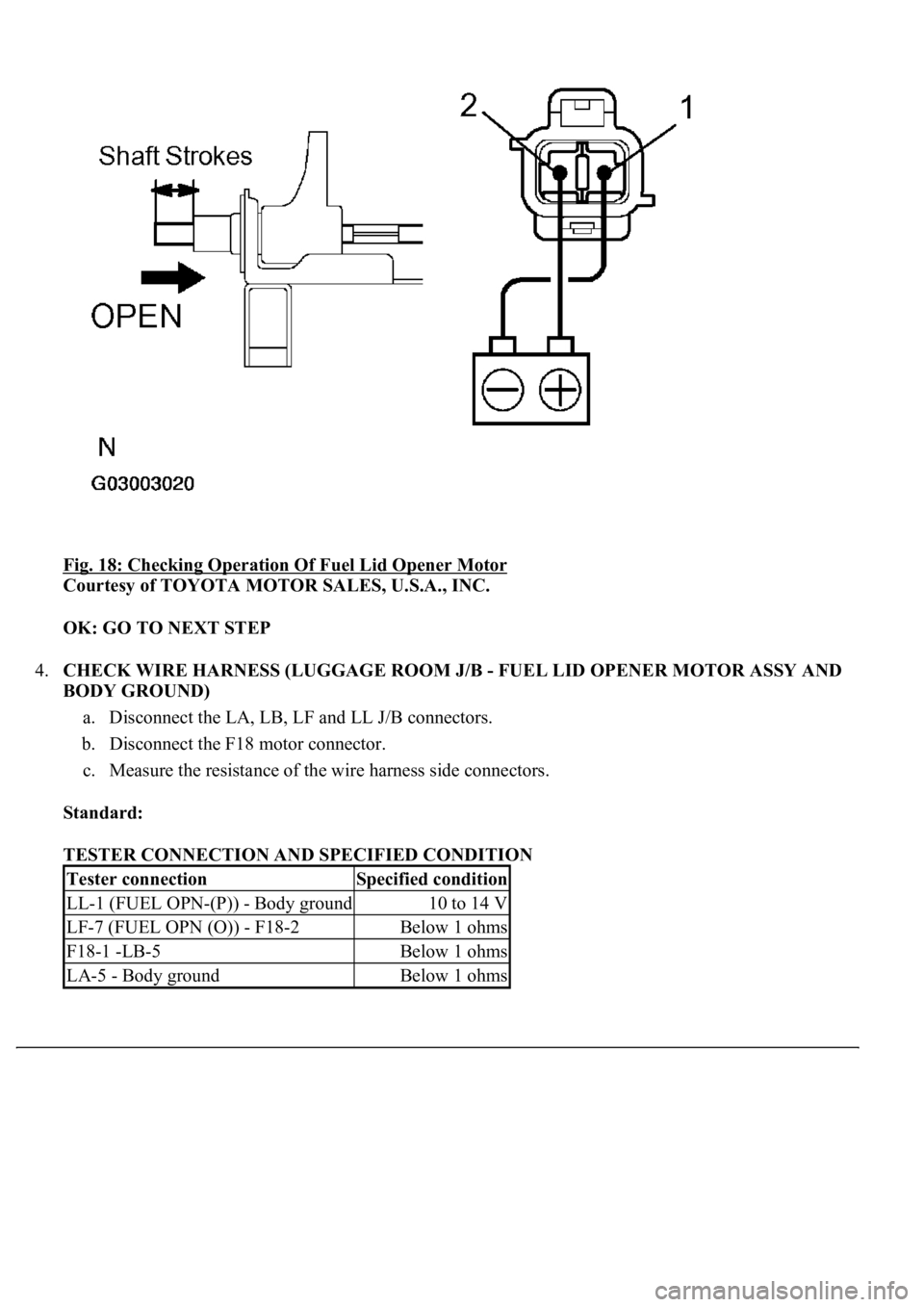
a. Apply battery voltage to the motor and check operation of the fuel lid opener motor.
OK:
MEASUREMENT CONDITION
NG: REPLACE FUEL LID OPENER MOTOR ASSY
ItemTest DetailDiagnostic Note
FUEL LID OPENOperate fuel lid motor OFF/ON-
Measurement ConditionSpecified Condition
Battery positive (+) --> Terminal 2 Battery negative (-) --> Terminal 1Moves to open direction
Page 4094 of 4500
<0029004c004a001100030014001b001d00030026004b00480046004e004c0051004a0003003200530048005500440057004c005200510003003200490003002900580048004f0003002f004c00470003003200530048005100480055000300300052005700
520055[
Courtesy of TOYOTA MOTOR SALES, U.S.A., INC.
OK: GO TO NEXT STEP
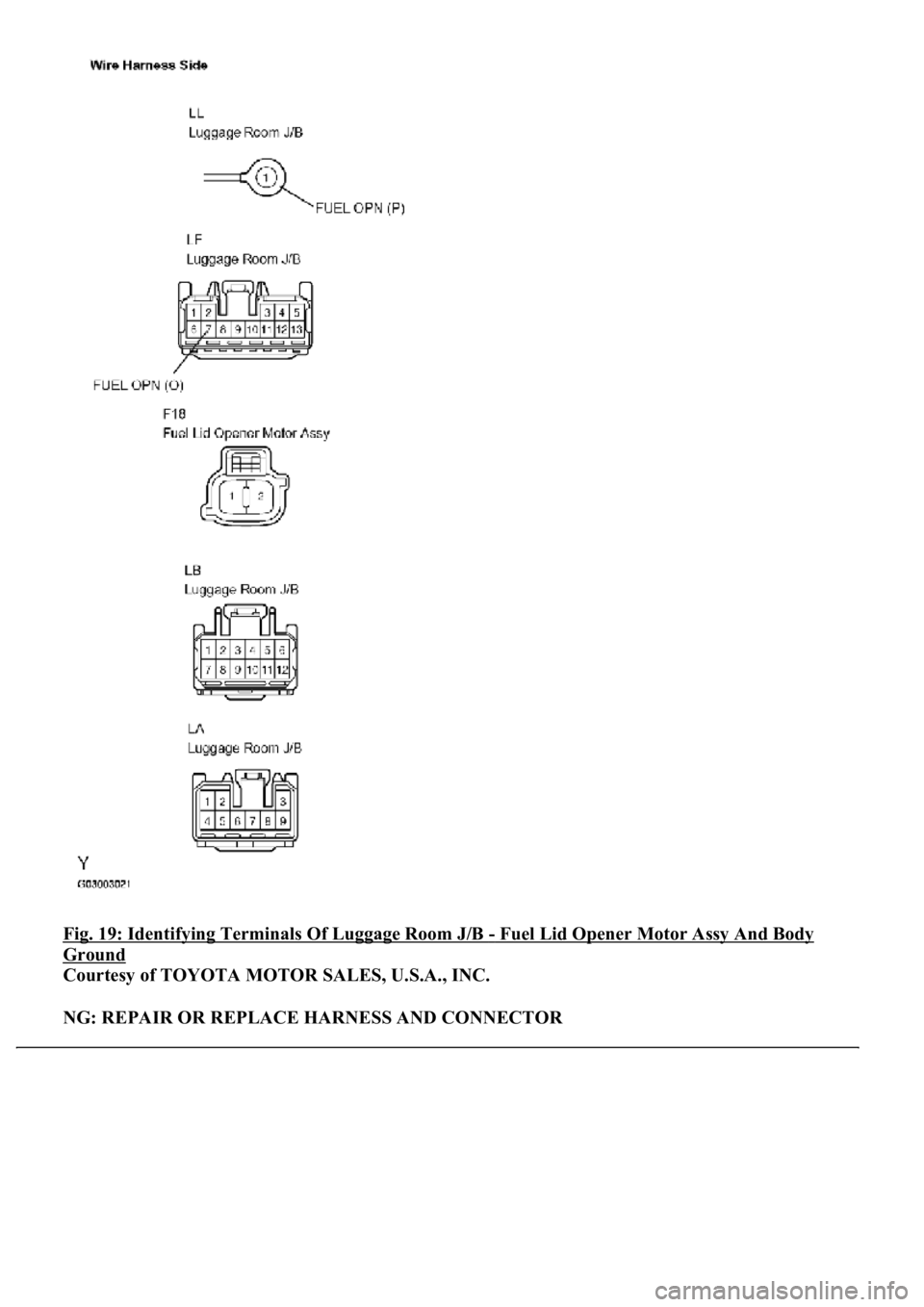
4.CHECK WIRE HARNESS (LUGGAGE ROOM J/B - FUEL LID OPENER MOTOR ASSY AND
BODY GROUND)
a. Disconnect the LA, LB, LF and LL J/B connectors.
b. Disconnect the F18 motor connector.
c. Measure the resistance of the wire harness side connectors.
Standard:
TESTER CONNECTION AND SPECIFIED CONDITION
Tester connectionSpecified condition
LL-1 (FUEL OPN-(P)) - Body ground10 to 14 V
LF-7 (FUEL OPN (O)) - F18-2Below 1 ohms
F18-1 -LB-5Below 1 ohms
LA-5 - Body groundBelow 1 ohms
Page 4095 of 4500
Fig. 19: Identifying Terminals Of Luggage Room J/B - Fuel Lid Opener Motor Assy And Body
Ground
Courtesy of TOYOTA MOTOR SALES, U.S.A., INC.
NG: REPAIR OR REPLACE HARNESS AND CONNECTOR
Page 4096 of 4500
OK: PROCEED TO NEXT CIRCUIT INSPECTION SHOWN ON PROBLEM SYMPTOMS
TABLE
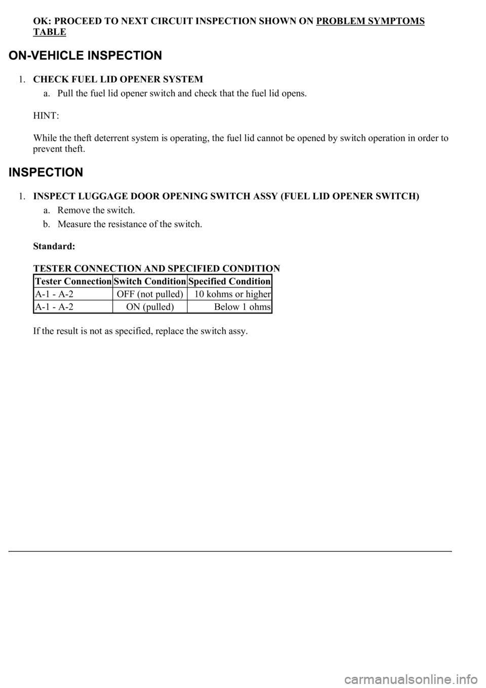
1.CHECK FUEL LID OPENER SYSTEM
a. Pull the fuel lid opener switch and check that the fuel lid opens.
HINT:
While the theft deterrent system is operating, the fuel lid cannot be opened by switch operation in order to
prevent theft.
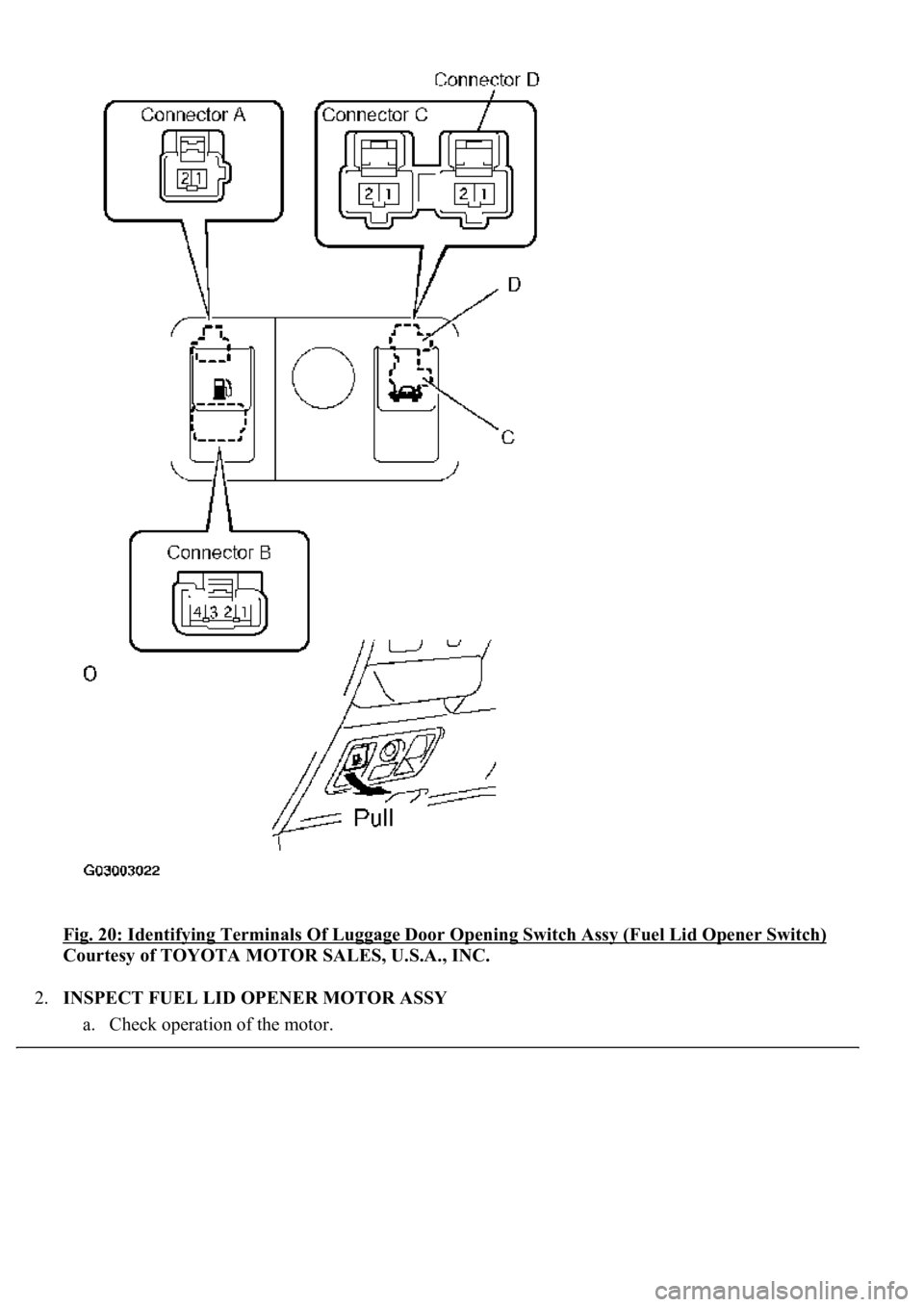
1.INSPECT LUGGAGE DOOR OPENING SWITCH ASSY (FUEL LID OPENER SWITCH)
a. Remove the switch.
b. Measure the resistance of the switch.
Standard:
TESTER CONNECTION AND SPECIFIED CONDITION
If the result is not as specified, replace the switch ass
y.
Tester ConnectionSwitch ConditionSpecified Condition
A-1 - A-2OFF (not pulled)10 kohms or higher
A-1 - A-2ON (pulled)Below 1 ohms
Page 4097 of 4500
Fig. 20: Identifying Terminals Of Luggage Door Opening Switch Assy (Fuel Lid Opener Switch)
Courtesy of TOYOTA MOTOR SALES, U.S.A., INC.
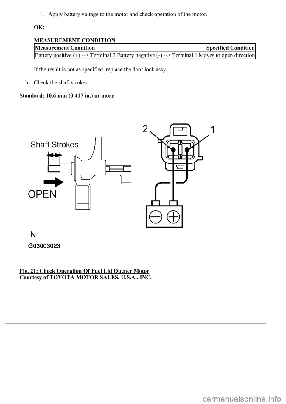
2.INSPECT FUEL LID OPENER MOTOR ASSY
a. Check operation of the motor.
Page 4098 of 4500
1. Apply battery voltage to the motor and check operation of the motor.
OK:
MEASUREMENT CONDITION
If the result is not as specified, replace the door lock assy.
b. Check the shaft strokes.
Standard: 10.6 mm (0.417 in.) or more
Fig. 21: Check Operation Of Fuel Lid Opener Motor
Courtesy of TOYOTA MOTOR SALES, U.S.A., INC.
Measurement ConditionSpecified Condition
Battery positive (+) --> Terminal 2 Battery negative (-) --> Terminal 1Moves to open direction
Page 4099 of 4500
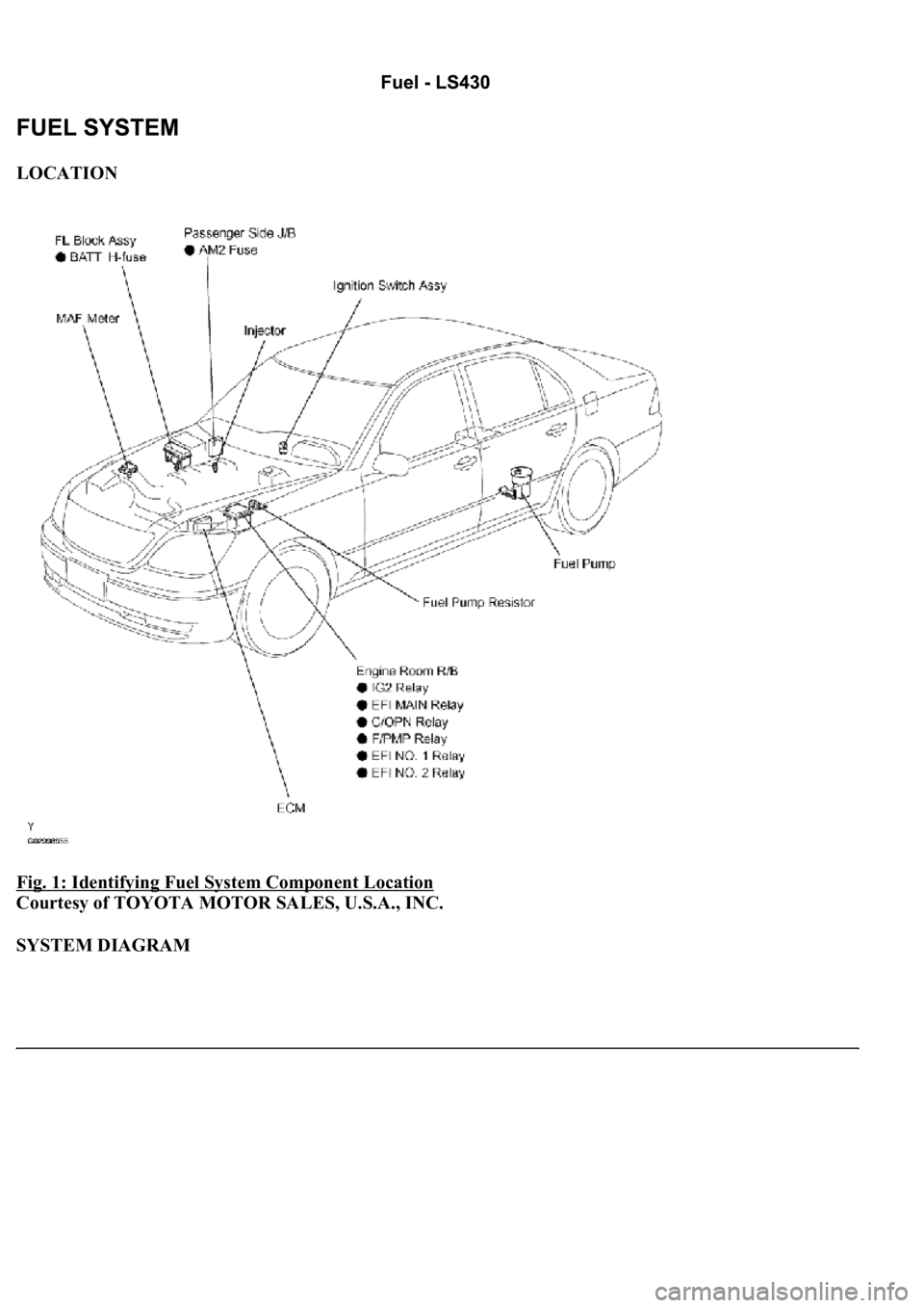
LOCATION
Fig. 1: Identifying Fuel System Component Location
Courtesy of TOYOTA MOTOR SALES, U.S.A., INC.
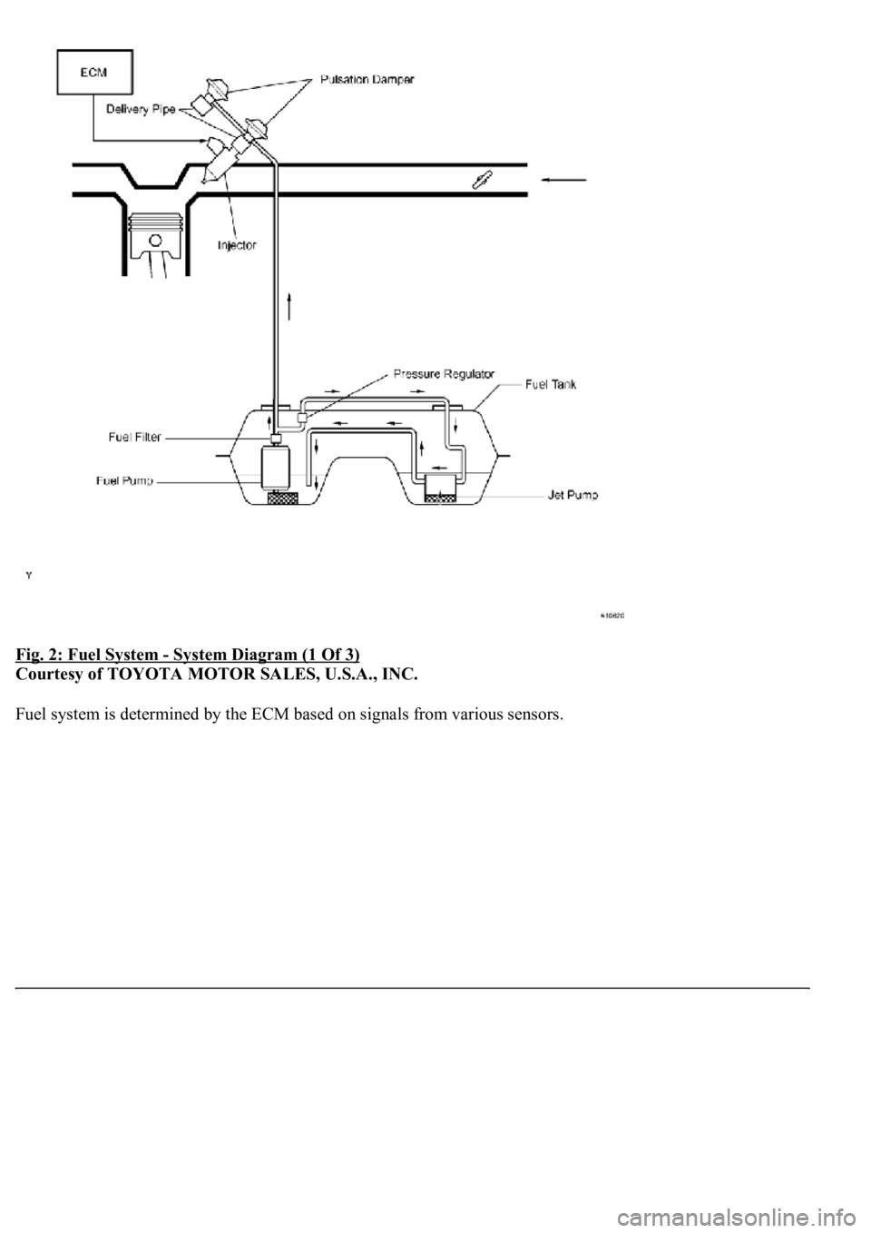
SYSTEM DIAGRAM
Page 4100 of 4500
Fig. 2: Fuel System - System Diagram (1 Of 3)
Courtesy of TOYOTA MOTOR SALES, U.S.A., INC.
Fuel s
ystem is determined by the ECM based on signals from various sensors.
Trending: radio, Modulated, fuel pump, ground clearance, automatic transmission, air bleeding, fuel filter
