LEXUS LS430 2003 Factory Repair Manual
Manufacturer: LEXUS, Model Year: 2003,
Model line: LS430,
Model: LEXUS LS430 2003
Pages: 4500, PDF Size: 87.45 MB
LEXUS LS430 2003 Factory Repair Manual
LS430 2003
LEXUS
LEXUS
https://www.carmanualsonline.info/img/36/57050/w960_57050-0.png
LEXUS LS430 2003 Factory Repair Manual
Trending: Modulated, trip computer, radio antenna, check engine, service reset, parking brake, engine coolant
Page 4071 of 4500
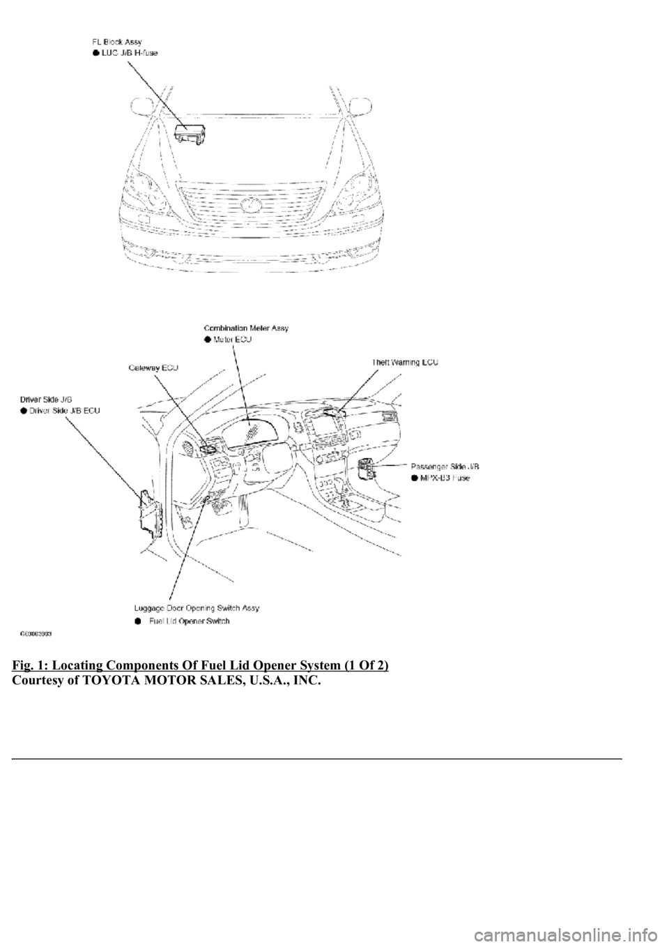
Fig. 1: Locating Components Of Fuel Lid Opener System (1 Of 2)
Courtesy of TOYOTA MOTOR SALES, U.S.A., INC.
Page 4072 of 4500
Fig. 2: Locating Components Of Fuel Lid Opener System (2 Of 2)
Courtesy of TOYOTA MOTOR SALES, U.S.A., INC.
Page 4073 of 4500
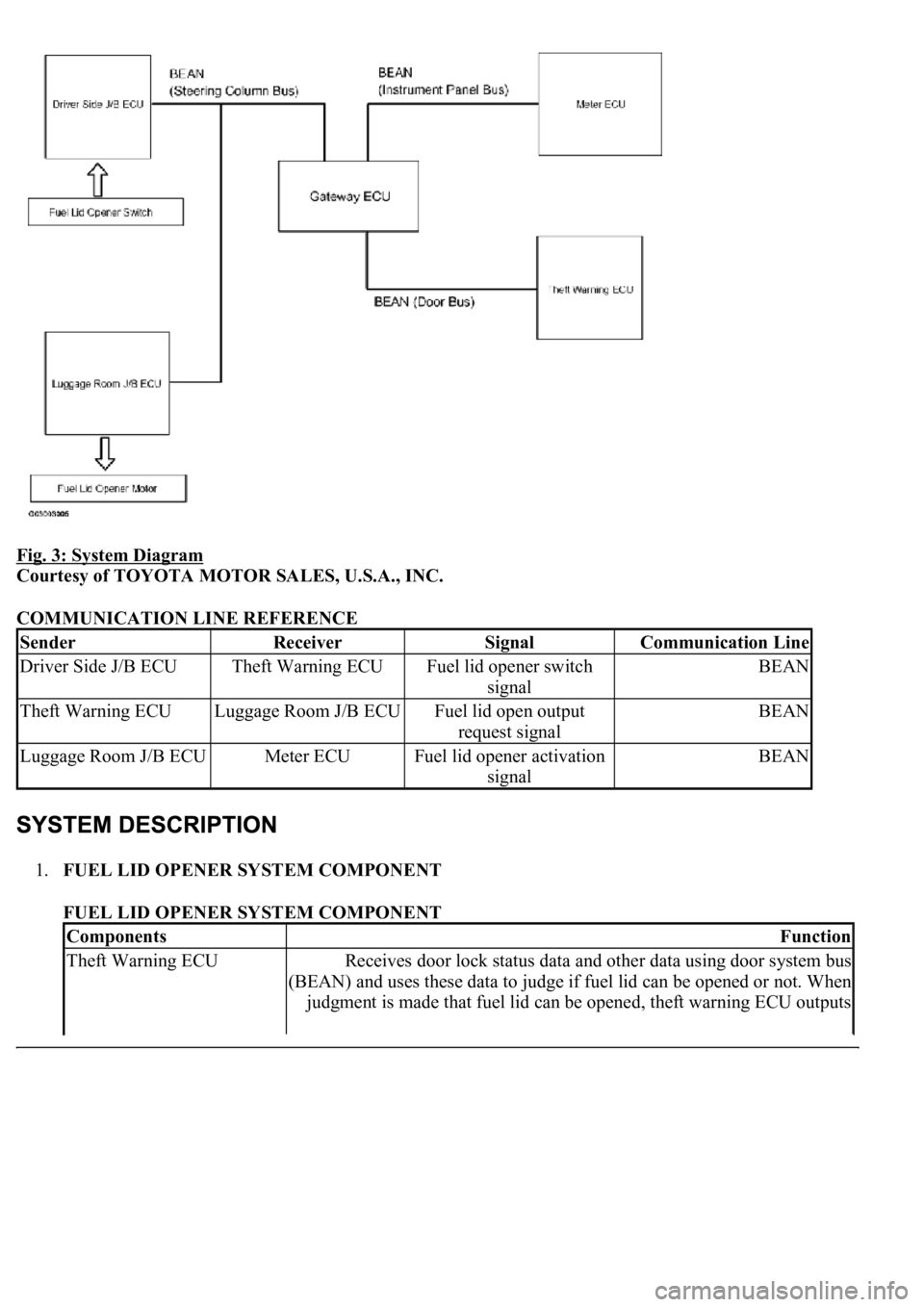
Fig. 3: System Diagram
Courtesy of TOYOTA MOTOR SALES, U.S.A., INC.
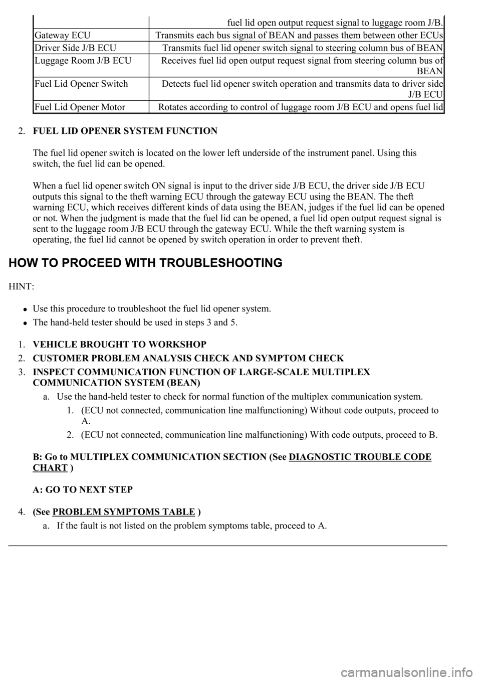
COMMUNICATION LINE REFERENCE
1.FUEL LID OPENER SYSTEM COMPONENT
FUEL LID OPENER SYSTEM COMPONENT
SenderReceiverSignalCommunication Line
Driver Side J/B ECUTheft Warning ECUFuel lid opener switch
signalBEAN
Theft Warning ECULuggage Room J/B ECUFuel lid open output
request signalBEAN
Luggage Room J/B ECUMeter ECUFuel lid opener activation
signalBEAN
ComponentsFunction
Theft Warning ECUReceives door lock status data and other data using door system bus
(BEAN) and uses these data to judge if fuel lid can be opened or not. When
judgment is made that fuel lid can be opened, theft warning ECU outputs
Page 4074 of 4500
2.FUEL LID OPENER SYSTEM FUNCTION
The fuel lid opener switch is located on the lower left underside of the instrument panel. Using this
switch, the fuel lid can be opened.
When a fuel lid opener switch ON signal is input to the driver side J/B ECU, the driver side J/B ECU
outputs this signal to the theft warning ECU through the gateway ECU using the BEAN. The theft
warning ECU, which receives different kinds of data using the BEAN, judges if the fuel lid can be opened
or not. When the judgment is made that the fuel lid can be opened, a fuel lid open output request signal is
sent to the luggage room J/B ECU through the gateway ECU. While the theft warning system is
operating, the fuel lid cannot be opened by switch operation in order to prevent theft.
HINT:
Use this procedure to troubleshoot the fuel lid opener system.
<0037004b00480003004b0044005100470010004b0048004f0047000300570048005600570048005500030056004b00520058004f0047000300450048000300580056004800470003004c005100030056005700480053005600030016000300440051004700
030018001100030003[
1.VEHICLE BROUGHT TO WORKSHOP
2.CUSTOMER PROBLEM ANALYSIS CHECK AND SYMPTOM CHECK
3.INSPECT COMMUNICATION FUNCTION OF LARGE-SCALE MULTIPLEX
COMMUNICATION SYSTEM (BEAN)
a. Use the hand-held tester to check for normal function of the multiplex communication system.
1. (ECU not connected, communication line malfunctioning) Without code outputs, proceed to
A.
2. (ECU not connected, communication line malfunctioning) With code outputs, proceed to B.
B: Go to MULTIPLEX COMMUNICATION SECTION (See DIAGNOSTIC TROUBLE CODE
CHART )
A: GO TO NEXT STEP
4.(See PROBLEM SYMPTOMS TABLE
)
a. If the fault is not listed on the problem s
ymptoms table, proceed to A.
fuel lid open output request signal to luggage room J/B.
Gateway ECUTransmits each bus signal of BEAN and passes them between other ECUs
Driver Side J/B ECUTransmits fuel lid opener switch signal to steering column bus of BEAN
Luggage Room J/B ECUReceives fuel lid open output request signal from steering column bus of
BEAN
Fuel Lid Opener SwitchDetects fuel lid opener switch operation and transmits data to driver side
J/B ECU
Fuel Lid Opener MotorRotates according to control of luggage room J/B ECU and opens fuel lid
Page 4075 of 4500
b. If the fault is listed on the problem symptoms table, proceed to B.
B: Go to step 6
A: GO TO NEXT STEP
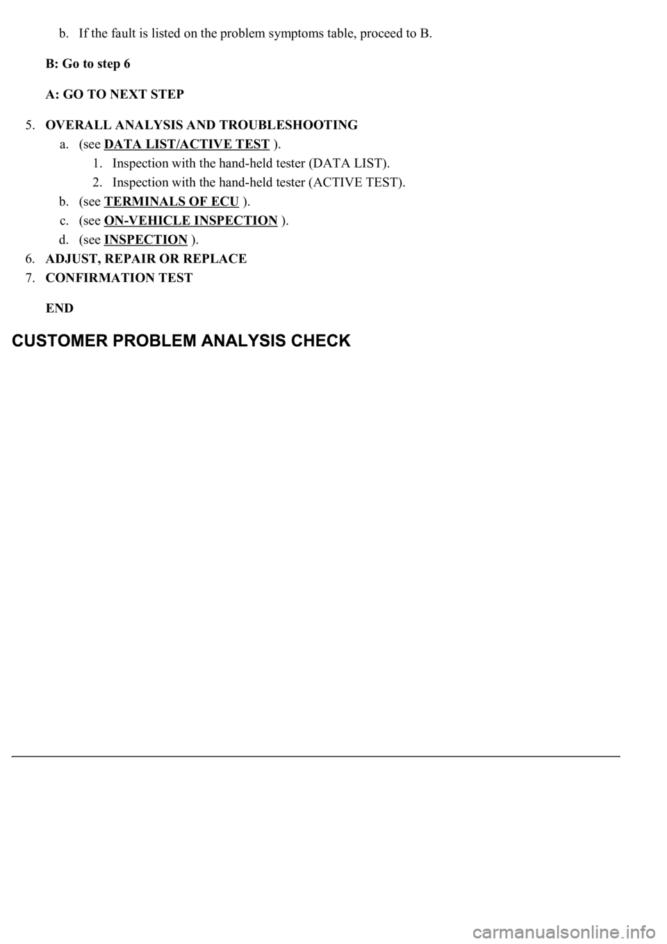
5.OVERALL ANALYSIS AND TROUBLESHOOTING
a. (see DATA LIST/ACTIVE TEST
).
1. Inspection with the hand-held tester (DATA LIST).
2. Inspection with the hand-held tester (ACTIVE TEST).
b. (see TERMINALS OF ECU
).
c. (see ON
-VEHICLE INSPECTION ).
d. (see INSPECTION
).
6.ADJUST, REPAIR OR REPLACE
7.CONFIRMATION TEST
END
Page 4076 of 4500
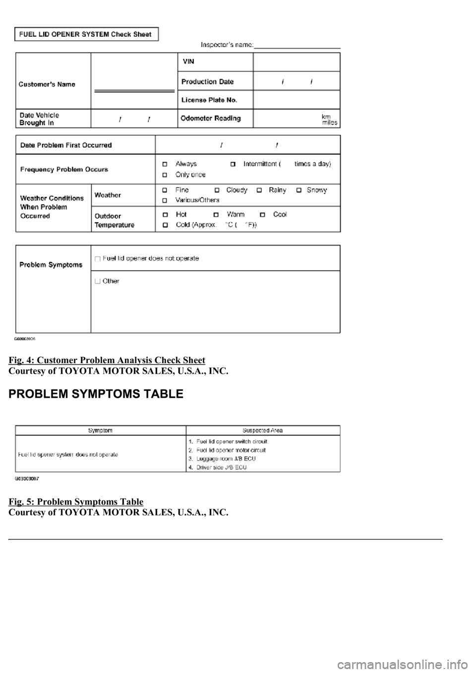
Fig. 4: Customer Problem Analysis Check Sheet
Courtesy of TOYOTA MOTOR SALES, U.S.A., INC.
Fig. 5: Problem Symptoms Table
Courtesy of TOYOTA MOTOR SALES, U.S.A., INC.
Page 4077 of 4500
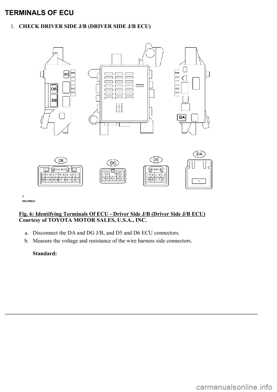
1.CHECK DRIVER SIDE J/B (DRIVER SIDE J/B ECU)
Fig. 6: Identifying Terminals Of ECU
- Driver Side J/B (Driver Side J/B ECU)
Courtesy of TOYOTA MOTOR SALES, U.S.A., INC.
a. Disconnect the DA and DG J/B, and D5 and D6 ECU connectors.
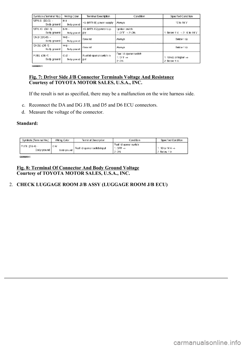
b. Measure the voltage and resistance of the wire harness side connectors.
Standard:
Page 4078 of 4500
Fig. 7: Driver Side J/B Connector Terminals Voltage And Resistance
Courtesy of TOYOTA MOTOR SALES, U.S.A., INC.
If the result is not as specified, there may be a malfunction on the wire harness side.
c. Reconnect the DA and DG J/B, and D5 and D6 ECU connectors.
d. Measure the voltage of the connector.
Standard:
Fig. 8: Terminal Of Connector And Body Ground Voltage
Courtesy of TOYOTA MOTOR SALES, U.S.A., INC.
2.CHECK LUGGAGE ROOM J/B ASSY (LUGGAGE ROOM J/B ECU)
Page 4079 of 4500
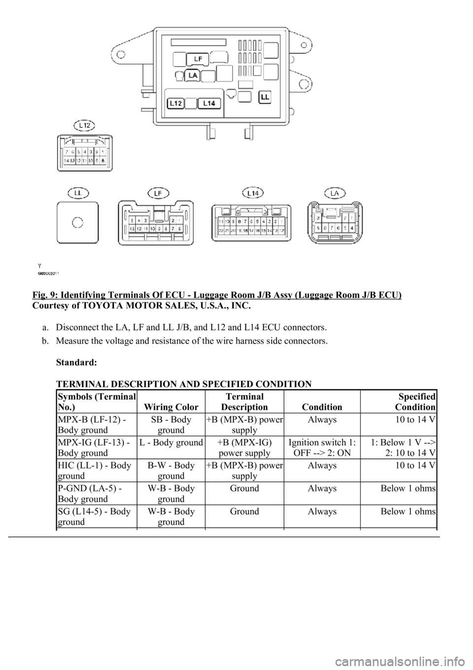
Fig. 9: Identifying Terminals Of ECU - Luggage Room J/B Assy (Luggage Room J/B ECU)
Courtesy of TOYOTA MOTOR SALES, U.S.A., INC.
a. Disconnect the LA, LF and LL J/B, and L12 and L14 ECU connectors.
b. Measure the voltage and resistance of the wire harness side connectors.
Standard:
TERMINAL DESCRIPTION AND SPECIFIED CONDITION
Symbols (Terminal
No.)
Wiring Color
Terminal
Description
Condition
Specified
Condition
MPX-B (LF-12) -
Body groundSB - Body
ground+B (MPX-B) power
supplyAlways10 to 14 V
MPX-IG (LF-13) -
Body groundL - Body ground+B (MPX-IG)
power supplyIgnition switch 1:
OFF --> 2: ON1: Below 1 V -->
2: 10 to 14 V
HIC (LL-1) - Body
groundB-W - Body
ground+B (MPX-B) power
supplyAlways10 to 14 V
P-GND (LA-5) -
Body groundW-B - Body
groundGroundAlwaysBelow 1 ohms
SG (L14-5) - Body
groundW-B - Body
groundGroundAlwaysBelow 1 ohms
Page 4080 of 4500
If the result is not as specified, there may be a malfunction on the wire harness side.
c. Reconnect the LA, LF and LL J/B, and L12 and L14 ECU connectors.
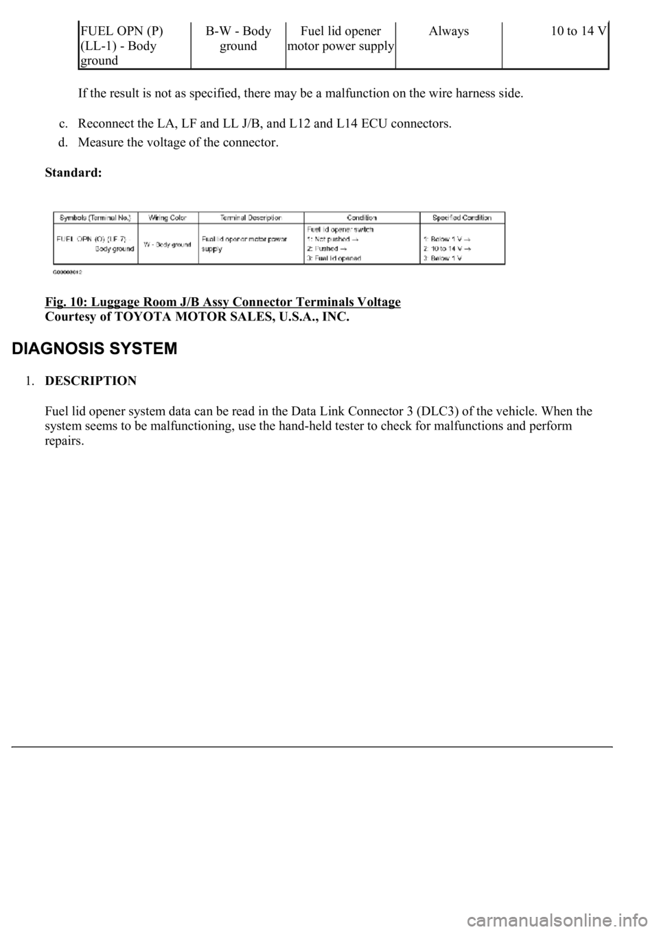
d. Measure the voltage of the connector.
Standard:
Fig. 10: Luggage Room J/B Assy Connector Terminals Voltage
Courtesy of TOYOTA MOTOR SALES, U.S.A., INC.
1.DESCRIPTION
Fuel lid opener system data can be read in the Data Link Connector 3 (DLC3) of the vehicle. When the
system seems to be malfunctioning, use the hand-held tester to check for malfunctions and perform
repairs.
FUEL OPN (P)
(LL-1) - Body
groundB-W - Body
groundFuel lid opener
motor power supplyAlways10 to 14 V
Trending: window, torque, shock absorber, oil pressure, transmission oil, park, v belt tensioner pulley
