LEXUS LS430 2003 Factory Repair Manual
Manufacturer: LEXUS, Model Year: 2003,
Model line: LS430,
Model: LEXUS LS430 2003
Pages: 4500, PDF Size: 87.45 MB
LEXUS LS430 2003 Factory Repair Manual
LS430 2003
LEXUS
LEXUS
https://www.carmanualsonline.info/img/36/57050/w960_57050-0.png
LEXUS LS430 2003 Factory Repair Manual
Trending: cylinder head, Identifying ac, diagram, vacuum switching valve, mileage, checking oil, evaporator removal
Page 4111 of 4500
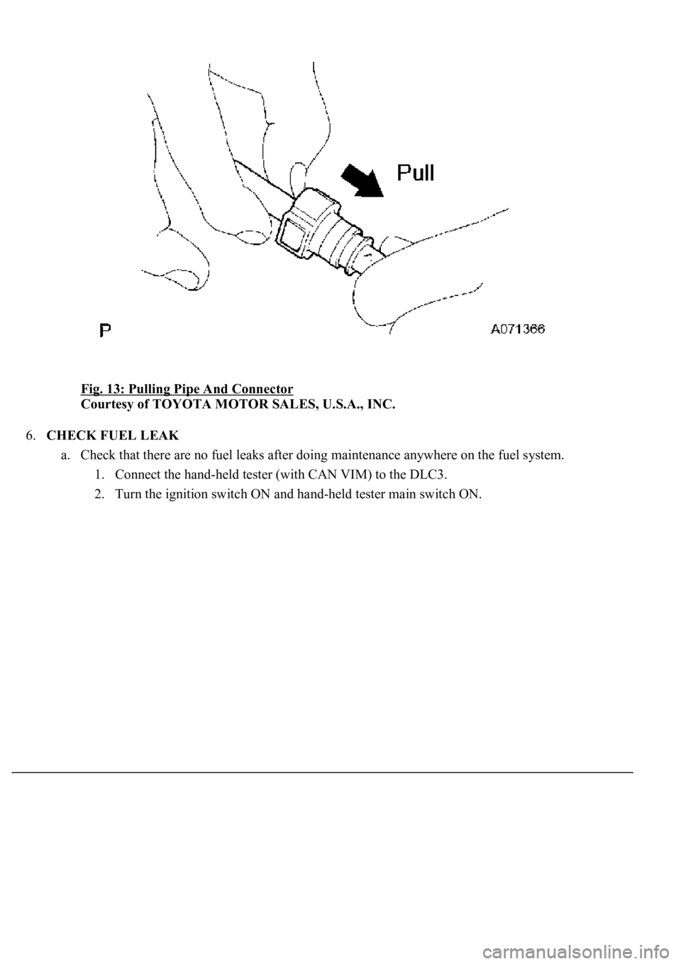
Fig. 13: Pulling Pipe And Connector
Courtesy of TOYOTA MOTOR SALES, U.S.A., INC.
6.CHECK FUEL LEAK
a. Check that there are no fuel leaks after doing maintenance anywhere on the fuel system.
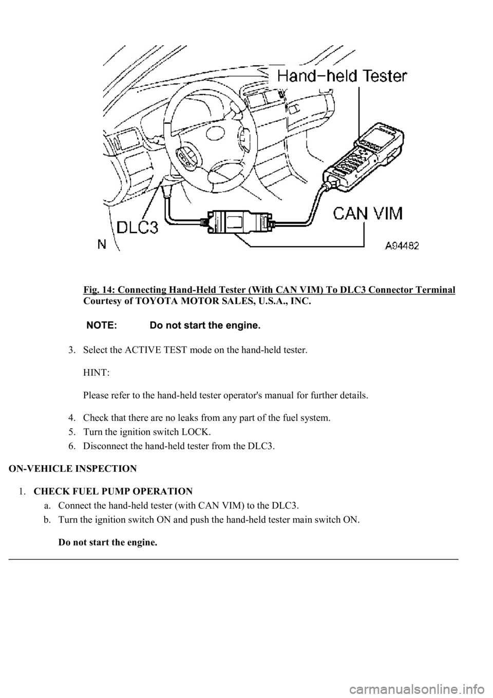
1. Connect the hand-held tester (with CAN VIM) to the DLC3.
2. Turn the i
gnition switch ON and hand-held tester main switch ON.
Page 4112 of 4500
Fig. 14: Connecting Hand-Held Tester (With CAN VIM) To DLC3 Connector Terminal
Courtesy of TOYOTA MOTOR SALES, U.S.A., INC.
3. Select the ACTIVE TEST mode on the hand-held tester.
HINT:
Please refer to the hand-held tester operator's manual for further details.
4. Check that there are no leaks from any part of the fuel system.
5. Turn the ignition switch LOCK.
6. Disconnect the hand-held tester from the DLC3.
ON-VEHICLE INSPECTION
1.CHECK FUEL PUMP OPERATION
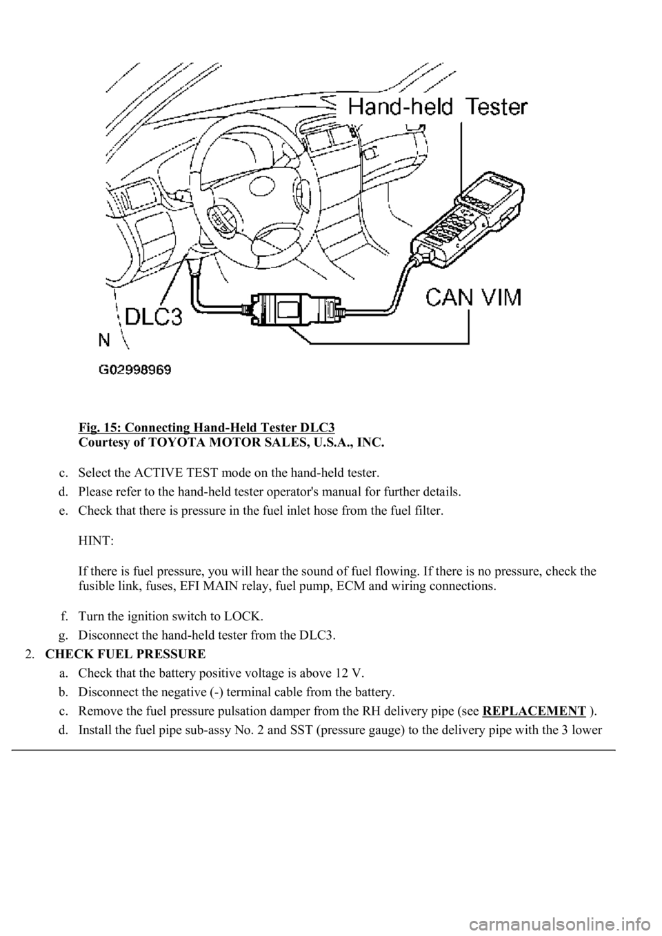
a. Connect the hand-held tester (with CAN VIM) to the DLC3.
b. Turn the ignition switch ON and push the hand-held tester main switch ON.
Do not start the engine.
Page 4113 of 4500
Fig. 15: Connecting Hand-Held Tester DLC3
Courtesy of TOYOTA MOTOR SALES, U.S.A., INC.
c. Select the ACTIVE TEST mode on the hand-held tester.
d. Please refer to the hand-held tester operator's manual for further details.
e. Check that there is pressure in the fuel inlet hose from the fuel filter.
HINT:
If there is fuel pressure, you will hear the sound of fuel flowing. If there is no pressure, check the
fusible link, fuses, EFI MAIN relay, fuel pump, ECM and wiring connections.
f. Turn the ignition switch to LOCK.
g. Disconnect the hand-held tester from the DLC3.
2.CHECK FUEL PRESSURE
a. Check that the battery positive voltage is above 12 V.
b. Disconnect the negative (-) terminal cable from the battery.
c. Remove the fuel pressure pulsation damper from the RH delivery pipe (see REPLACEMENT
).
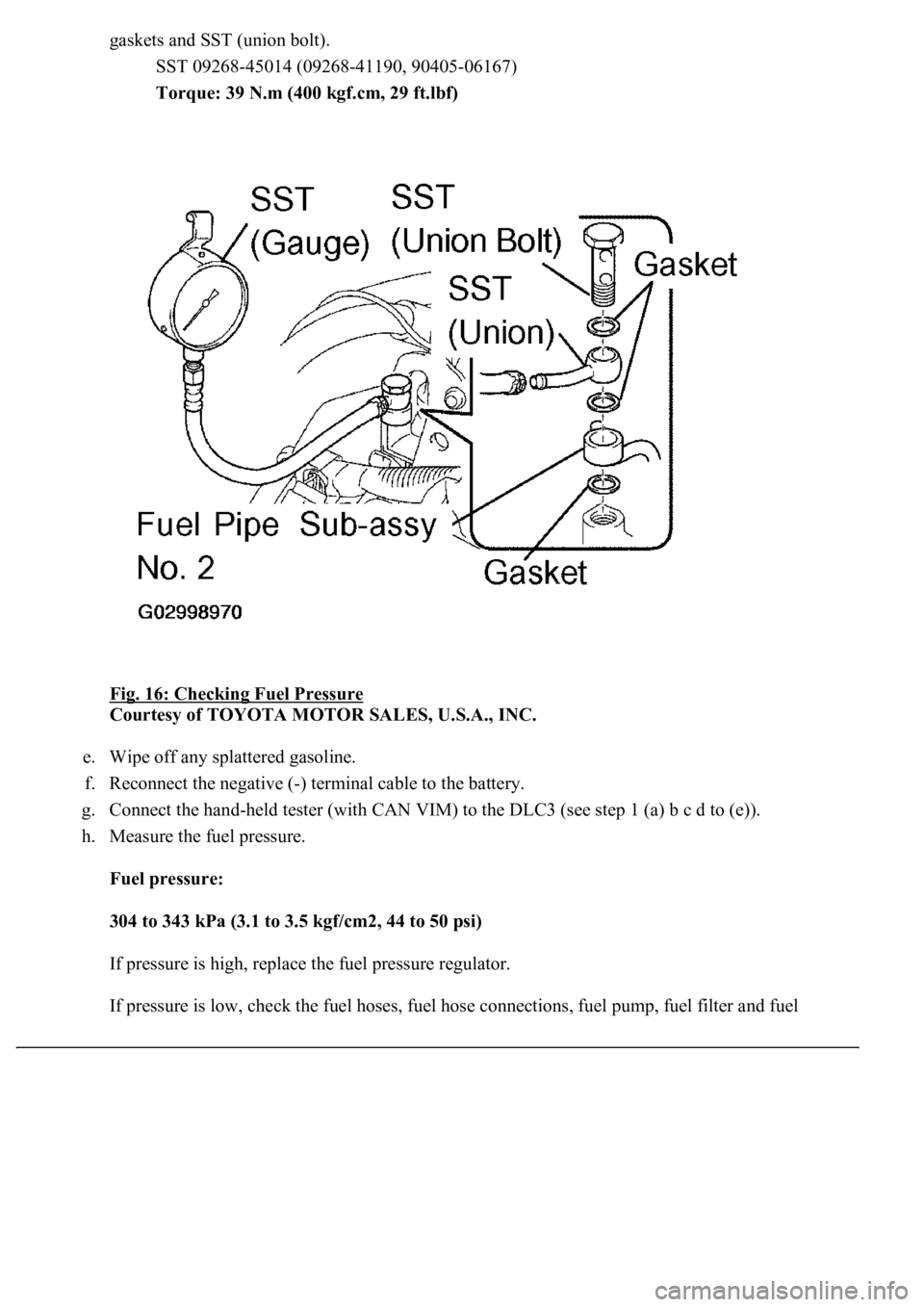
d. Install the fuel pipe sub-ass
y No. 2 and SST (pressure gauge) to the delivery pipe with the 3 lower
Page 4114 of 4500
gaskets and SST (union bolt).
SST 09268-45014 (09268-41190, 90405-06167)
Torque: 39 N.m (400 kgf.cm, 29 ft.lbf)
Fig. 16: Checking Fuel Pressure
Courtesy of TOYOTA MOTOR SALES, U.S.A., INC.
e. Wipe off any splattered gasoline.
f. Reconnect the negative (-) terminal cable to the battery.
g. Connect the hand-held tester (with CAN VIM) to the DLC3 (see step 1 (a) b c d to (e)).
h. Measure the fuel pressure.
Fuel pressure:
304 to 343 kPa (3.1 to 3.5 kgf/cm2, 44 to 50 psi)
If pressure is high, replace the fuel pressure regulator.
If pressure is low, check the fuel hoses, fuel hose connections, fuel pump, fuel filter and fuel
Page 4115 of 4500
pressure regulator.
i. Disconnect the hand-held tester from the DLC3.
j. Start the engine.
k. Measure the fuel pressure at idle.
Fuel pressure: 304 to 343 kPa (3.1 to 3.5 kgf/cm2, 44 to 50 psi)
l. Stop the engine.
m. Check that the fuel pressure remains as specified for 5 minutes after the engine has stopped.
Fuel pressure: 147 kPa (1.5 kgf/cm2, 21 psi) or more
If pressure is not as specified, check the fuel pump, pressure regulator and/or injectors.
n. After checking fuel pressure, disconnect the negative (-) terminal cable from the battery and
carefully remove the SST to prevent gasoline from spilling.
SST 09268-45014
o. Reinstall the fuel pressure pulsation damper to the RH delivery pipe (see REPLACEMENT
).
p. Reconnect the negative (-) terminal cable to the battery.
q. Check for fuel leaks.
3.INSPECT FUEL PUMP
Page 4116 of 4500
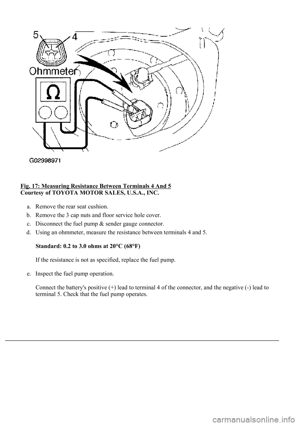
<0029004c004a001100030014001a001d0003003000480044005600580055004c0051004a0003003500480056004c0056005700440051004600480003002500480057005a00480048005100030037004800550050004c00510044004f005600030017000300
240051004700030018[
Courtesy of TOYOTA MOTOR SALES, U.S.A., INC.
a. Remove the rear seat cushion.
b. Remove the 3 cap nuts and floor service hole cover.
c. Disconnect the fuel pump & sender gauge connector.
d. Using an ohmmeter, measure the resistance between terminals 4 and 5.
Standard: 0.2 to 3.0 ohms at 20°C (68°F)
If the resistance is not as specified, replace the fuel pump.
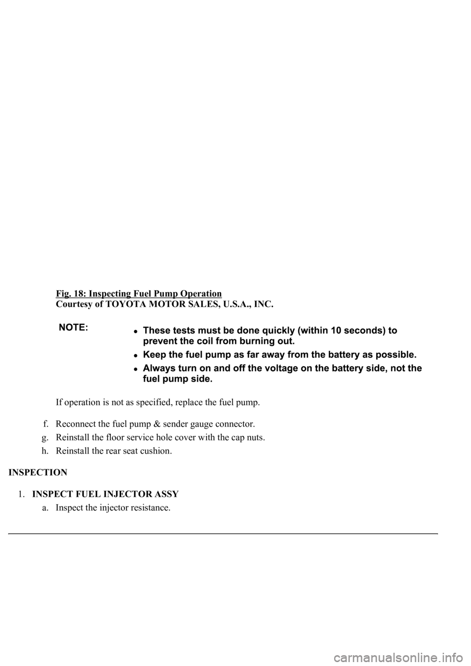
e. Inspect the fuel pump operation.
Connect the battery's positive (+) lead to terminal 4 of the connector, and the negative (-) lead to
terminal 5. Check that the fuel pump operates.
Page 4117 of 4500
Fig. 18: Inspecting Fuel Pump Operation
Courtesy of TOYOTA MOTOR SALES, U.S.A., INC.
<002c00490003005200530048005500440057004c005200510003004c0056000300510052005700030044005600030056005300480046004c0049004c00480047000f0003005500480053004f00440046004800030057004b00480003004900580048004f00
03005300580050005300110003[
f. Reconnect the fuel pump & sender gauge connector.
g. Reinstall the floor service hole cover with the cap nuts.
h. Reinstall the rear seat cushion.
INSPECTION
1.INSPECT FUEL INJECTOR ASSY
a. Inspect the in
jector resistance.
Page 4118 of 4500
Using an ohmmeter, measure the resistance between the terminals.
Standard: 13.4 to 14.2 ohms at 20°C (68°F)
HINT:
If the resistance is not as specified, replace the injector.
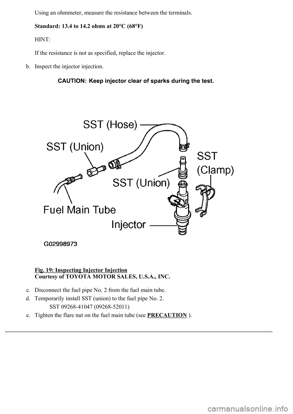
b. Inspect the injector injection.
Fig. 19: Inspecting Injector Injection
Courtesy of TOYOTA MOTOR SALES, U.S.A., INC.
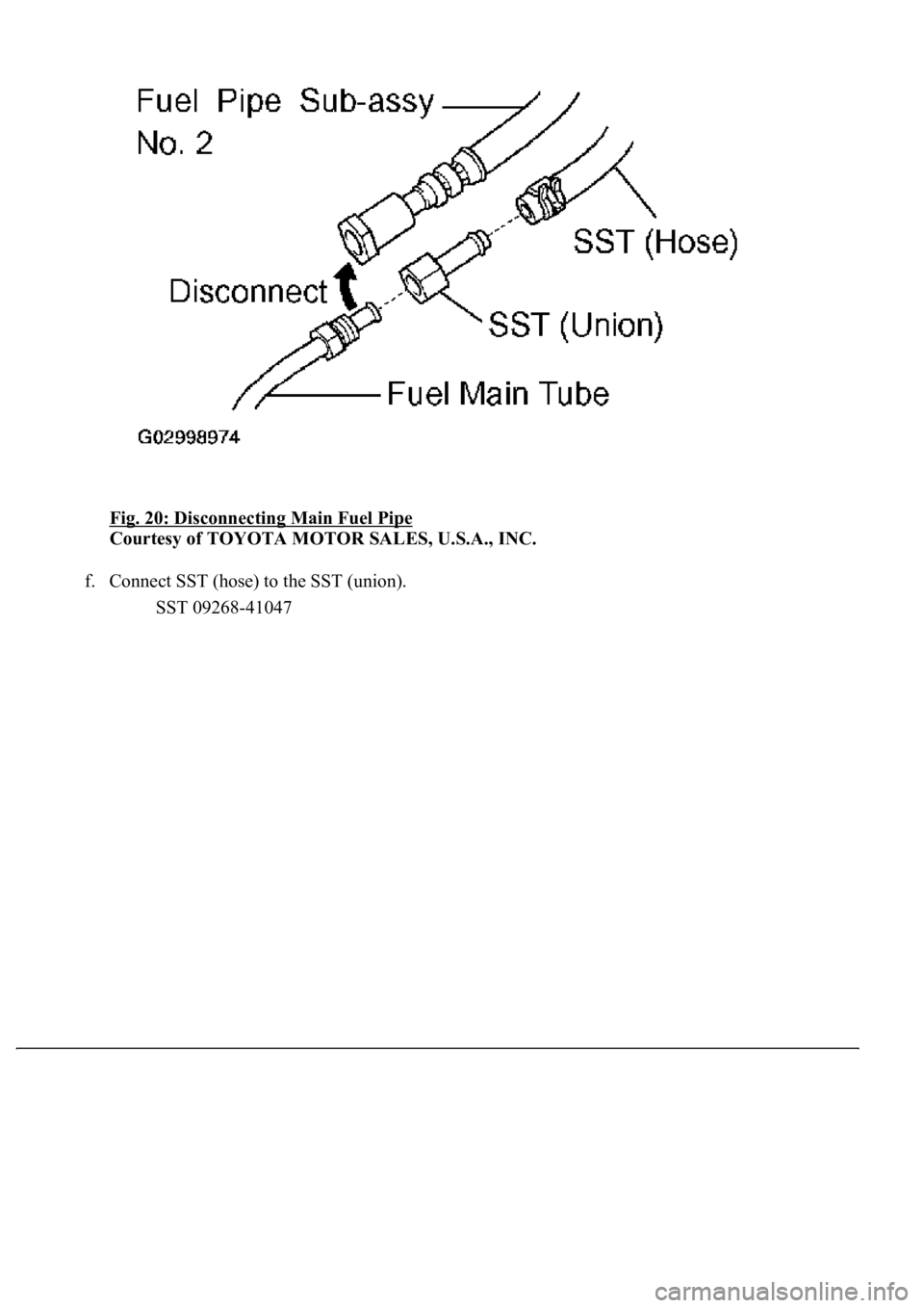
c. Disconnect the fuel pipe No. 2 from the fuel main tube.
d. Temporarily install SST (union) to the fuel pipe No. 2.
SST 09268-41047 (09268-52011)
e. Ti
ghten the flare nut on the fuel main tube (see PRECAUTION).
Page 4119 of 4500
Fig. 20: Disconnecting Main Fuel Pipe
Courtesy of TOYOTA MOTOR SALES, U.S.A., INC.
f. Connect SST (hose) to the SST (union).
SST 09268-41047
Page 4120 of 4500
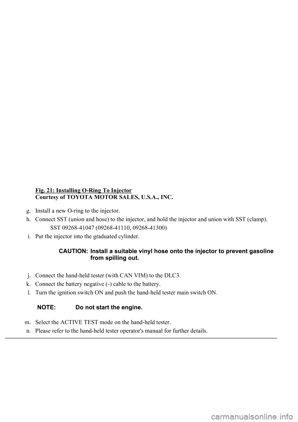
Fig. 21: Installing O-Ring To Injector
Courtesy of TOYOTA MOTOR SALES, U.S.A., INC.
g. Install a new O-ring to the injector.
h. Connect SST (union and hose) to the injector, and hold the injector and union with SST (clamp).
SST 09268-41047 (09268-41110, 09268-41300)
i. Put the injector into the graduated cylinder.
j. Connect the hand-held tester (with CAN VIM) to the DLC3.
k. Connect the battery negative (-) cable to the battery.
l. Turn the ignition switch ON and push the hand-held tester main switch ON.
m. Select the ACTIVE TEST mode on the hand-held tester.
n. Please refer to the han
d-held tester operator's manual for further details.
Trending: clock, differential, service indicator, wheel size, air condition, fuel system, B2620
