LEXUS LS430 2003 Factory Repair Manual
Manufacturer: LEXUS, Model Year: 2003,
Model line: LS430,
Model: LEXUS LS430 2003
Pages: 4500, PDF Size: 87.45 MB
LEXUS LS430 2003 Factory Repair Manual
LS430 2003
LEXUS
LEXUS
https://www.carmanualsonline.info/img/36/57050/w960_57050-0.png
LEXUS LS430 2003 Factory Repair Manual
Trending: clock, navigation update, spare tire, steering wheel adjustment, display, tow, Spark plug
Page 4381 of 4500
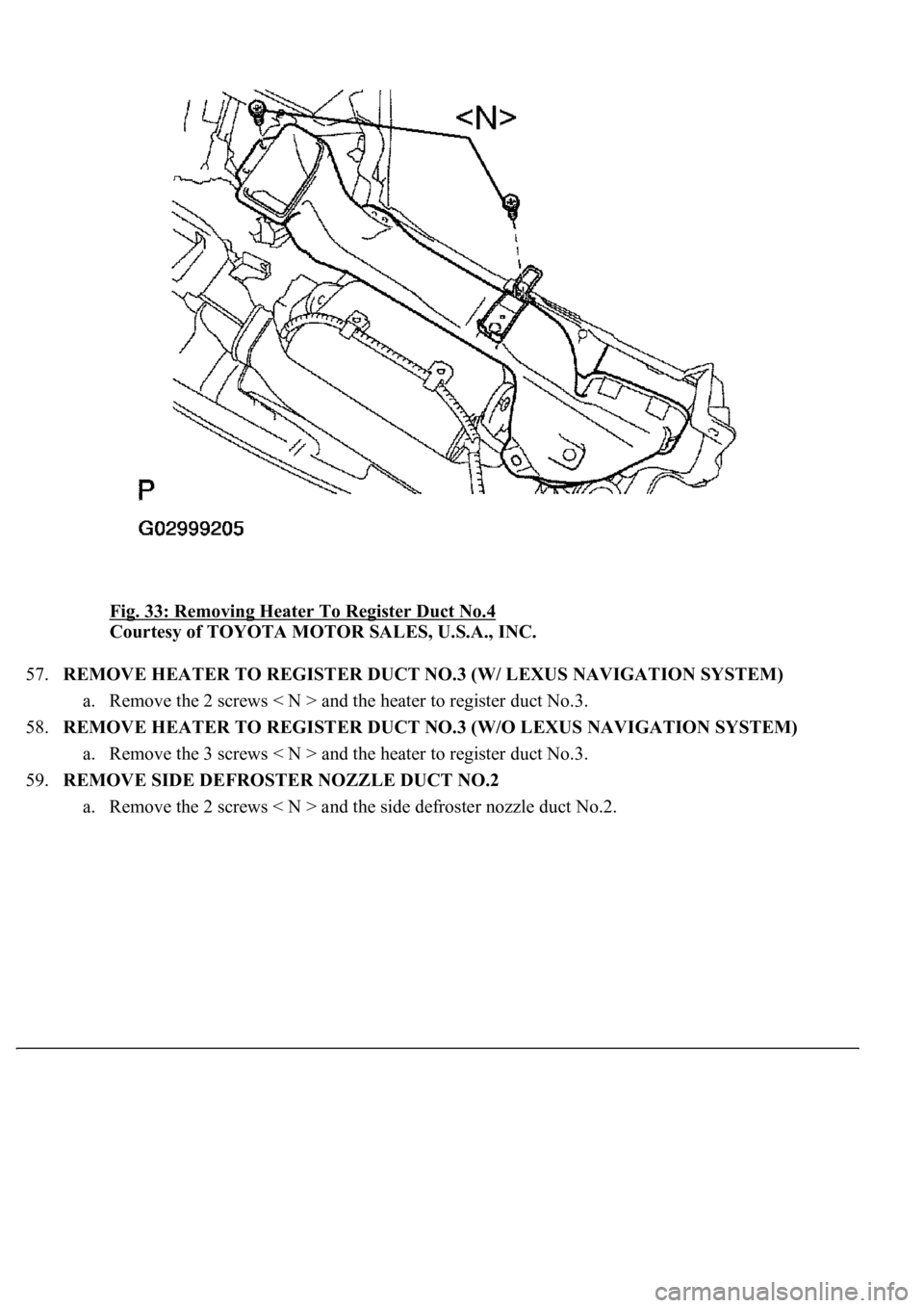
Fig. 33: Removing Heater To Register Duct No.4
Courtesy of TOYOTA MOTOR SALES, U.S.A., INC.
57.REMOVE HEATER TO REGISTER DUCT NO.3 (W/ LEXUS NAVIGATION SYSTEM)
a. Remove the 2 screws < N > and the heater to register duct No.3.
58.REMOVE HEATER TO REGISTER DUCT NO.3 (W/O LEXUS NAVIGATION SYSTEM)
a. Remove the 3 screws < N > and the heater to register duct No.3.
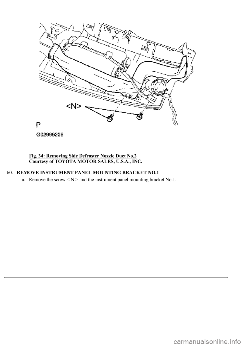
59.REMOVE SIDE DEFROSTER NOZZLE DUCT NO.2
a. Remove the 2 screws < N > and the side defroster nozzle duct No.2.
Page 4382 of 4500
Fig. 34: Removing Side Defroster Nozzle Duct No.2
Courtesy of TOYOTA MOTOR SALES, U.S.A., INC.
60.REMOVE INSTRUMENT PANEL MOUNTING BRACKET NO.1
a. Remove the screw < N > and the instrument panel mountin
g bracket No.1.
Page 4383 of 4500
Fig. 35: Removing Meter Hood Retainer No.1
Courtesy of TOYOTA MOTOR SALES, U.S.A., INC.
61.REMOVE METER HOOD RETAINER NO.1
a. Remove the screw < N > and the meter hood retainer No.1.
62.REMOVE NAVIGATION ANTENNA ASSY (W/LEXUS NAVIGATION SYSTEM) (SEE
REPLACEMENT
)
63.REMOVE FRONT NO.2 SPEAKER ASSY (SEE REPLACEMENT
)
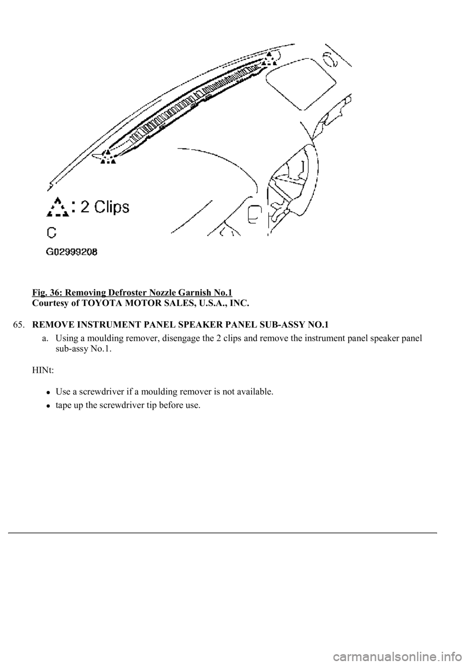
64.REMOVE DEFROSTER NOZZLE GARNISH NO.1
a. Using a moulding remover, disengage the 2 clips and remove the defroster nozzle garnish No.1.
HINt:
Use a screwdriver if a moulding remover is not available.
tape up the screwdriver tip before use.
Page 4384 of 4500
Fig. 36: Removing Defroster Nozzle Garnish No.1
Courtesy of TOYOTA MOTOR SALES, U.S.A., INC.
65.REMOVE INSTRUMENT PANEL SPEAKER PANEL SUB-ASSY NO.1
a. Using a moulding remover, disengage the 2 clips and remove the instrument panel speaker panel
sub-assy No.1.
HINt:
Use a screwdriver if a moulding remover is not available.
tape up the screwdriver tip before use.
Page 4385 of 4500
Fig. 37: Removing Instrument Panel Speaker Panel Sub-Assy No.1
Courtesy of TOYOTA MOTOR SALES, U.S.A., INC.
66.REMOVE INSTRUMENT PANEL SPEAKER PANEL SUB-ASSY NO.2
a. Use the same procedure described in the prior step.
67.REMOVE FRONT PASSENGER AIRBAG ASSY CONNECTOR (SEE REPLACEMENT
)
68.REMOVE INSTRUMENT PANEL SAFETY PAD SUB-ASSY
69.INSTALL FRONT PASSENGER AIRBAG ASSY CONNECTOR
70.INSTALL INSTRUMENT PANEL SAFETY PAD SUB-ASSY W/REINFORCEMENT ASSY
a. Install the instrument panel safety pad sub-assy w/reinforcement assy with the 9 bolts < A >, < C >,
< D >.
torque: 20 N.m (204 kgf.cm, 15 ft.Ibf)
Page 4386 of 4500
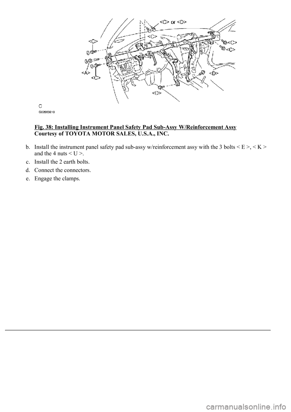
Fig. 38: Installing Instrument Panel Safety Pad Sub-Assy W/Reinforcement Assy
Courtesy of TOYOTA MOTOR SALES, U.S.A., INC.
b. Install the instrument panel safety pad sub-assy w/reinforcement assy with the 3 bolts < E >, < K >
and the 4 nuts < U >.
c. Install the 2 earth bolts.
d. Connect the connectors.
e. En
gage the clamps.
Page 4387 of 4500
Fig. 39: Installing Instrument Panel Safety Pad Sub-Assy W/Reinforcement Assy
Courtesy of TOYOTA MOTOR SALES, U.S.A., INC.
71.INSTALL STEERING COLUMN ASSY (SEE OVERHAUL
)
SSt 09921-00010
72.INSTALL INSTRUMENT PANEL AIR BAG ASSY LOWER NO.1
a. Connect the connectors.
b. Engage the clip and install the glove compartment door assy w/instrument panel airbag assy lower
No.2 with the 3 bolts < J > and the 3 screws < N >.
torque: 10 N.m (102 kgf.cm, 7 ft.Ibf)
Page 4388 of 4500
Fig. 40: Installing Instrument Panel Air Bag Assy Lower No.1
Courtesy of TOYOTA MOTOR SALES, U.S.A., INC.
73.INSTALL SPIRAL CABLE SUB-ASSY (SEE REPLACEMENT
)
74.CENTER SPIRAL CABLE (SEE REPLACEMENT
)
75.INSTALL STEERING WHEEL ASSY (SEE OVERHAUL
)
76.STEERING WHEEL CENTER POINT
77.INSTALL HORN BUTTON ASSY (SEE OVERHAUL
)
78.CONNECT BATTERY NEGATIVE TERMINAL
79.INSPECT HORN BUTTON ASSY (SEE REPLACEMENT
)
80.INSPECT SRS WARNING LIGHT (SEE DIAGNOSIS SYSTEM
)
81.PERFORM INITIALIZATION (SEE INITIALIZATION
)
OVERHAUL
HINt:
Page 4389 of 4500
SEE COMPONENTS
Installation is in the reverse order of removal.
1.REMOVE INSTRUMENT CLUSTER FINISH PANEL CENTER LOWER (SEE
REPLACEMENT
)
2.REMOVE INSTRUMENT CLUSTER FINISH PANEL END (SEE REPLACEMENT
)
3.REMOVE INSTRUMENT CLUSTER FINISH PANEL END (SEE REPLACEMENT
)
4.REMOVE COMBINATION METER ASSY (SEE REPLACEMENT
)
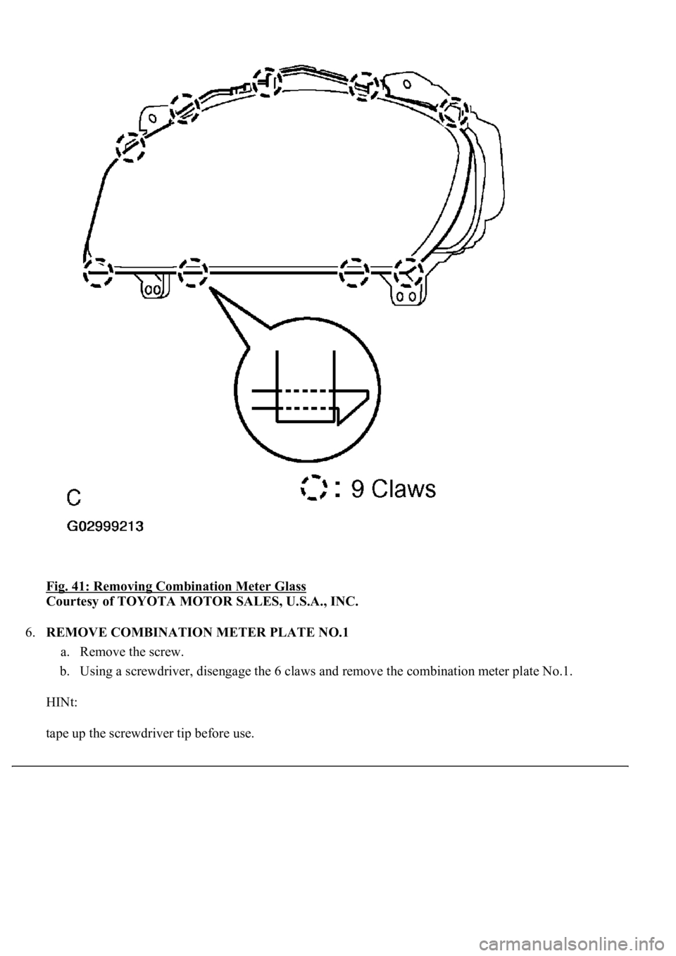
5.REMOVE COMBINATION METER GLASS
a. Using a screwdriver, disengage the 9 claws and remove the combination meter glass.
HINt:
tape up the screwdriver tip before use.
Page 4390 of 4500
Fig. 41: Removing Combination Meter Glass
Courtesy of TOYOTA MOTOR SALES, U.S.A., INC.
6.REMOVE COMBINATION METER PLATE NO.1
a. Remove the screw.
b. Using a screwdriver, disengage the 6 claws and remove the combination meter plate No.1.
HINt:
tape up the screwdriver tip before use.
Trending: instrument cluster, Absorber suspension, set clock, service interval, maintenance, wiring, air filter
