LEXUS LS430 2003 Factory Repair Manual
Manufacturer: LEXUS, Model Year: 2003,
Model line: LS430,
Model: LEXUS LS430 2003
Pages: 4500, PDF Size: 87.45 MB
LEXUS LS430 2003 Factory Repair Manual
LS430 2003
LEXUS
LEXUS
https://www.carmanualsonline.info/img/36/57050/w960_57050-0.png
LEXUS LS430 2003 Factory Repair Manual
Trending: wheel torque, Sp1, height, set clock, replacement, brake, spark plugs replace
Page 4341 of 4500
3.REMOVE V-BANK COVER
4.REMOVE ENGINE ROOM SIDE COVER
5.DISCONNECT RADIATOR HOSE NO. 1
6.REMOVE TIMING BELT COVER SUB-ASSY NO. 3 LH (See step 18 in REPLACEMENT
)
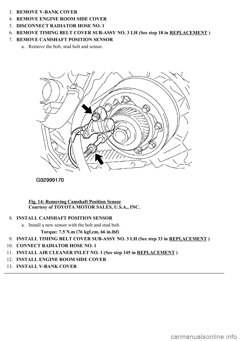
7.REMOVE CAMSHAFT POSITION SENSOR
a. Remove the bolt, stud bolt and sensor.
Fig. 14: Removing Camshaft Position Sensor
Courtesy of TOYOTA MOTOR SALES, U.S.A., INC.
8.INSTALL CAMSHAFT POSITION SENSOR
a. Install a new sensor with the bolt and stud bolt.
Torque: 7.5 N.m (76 kgf.cm, 66 in.lbf)
9.INSTALL TIMING BELT COVER SUB-ASSY NO. 3 LH (See step 33 in REPLACEMENT
)
10.CONNECT RADIATOR HOSE NO. 1
11.INSTALL AIR CLEANER INLET NO. 1 (See step 145 in REPLACEMENT
)
12.INSTALL ENGINE ROOM SIDE COVER
13.INSTALL V-BANK COVER
Page 4342 of 4500
14.REFILL ENGINE COOLANT (See REPLACEMENT )
15.WARM UP ENGINE
16.CHECK FOR ENGINE COOLANT LEAKS
COMPONENTS
Page 4343 of 4500
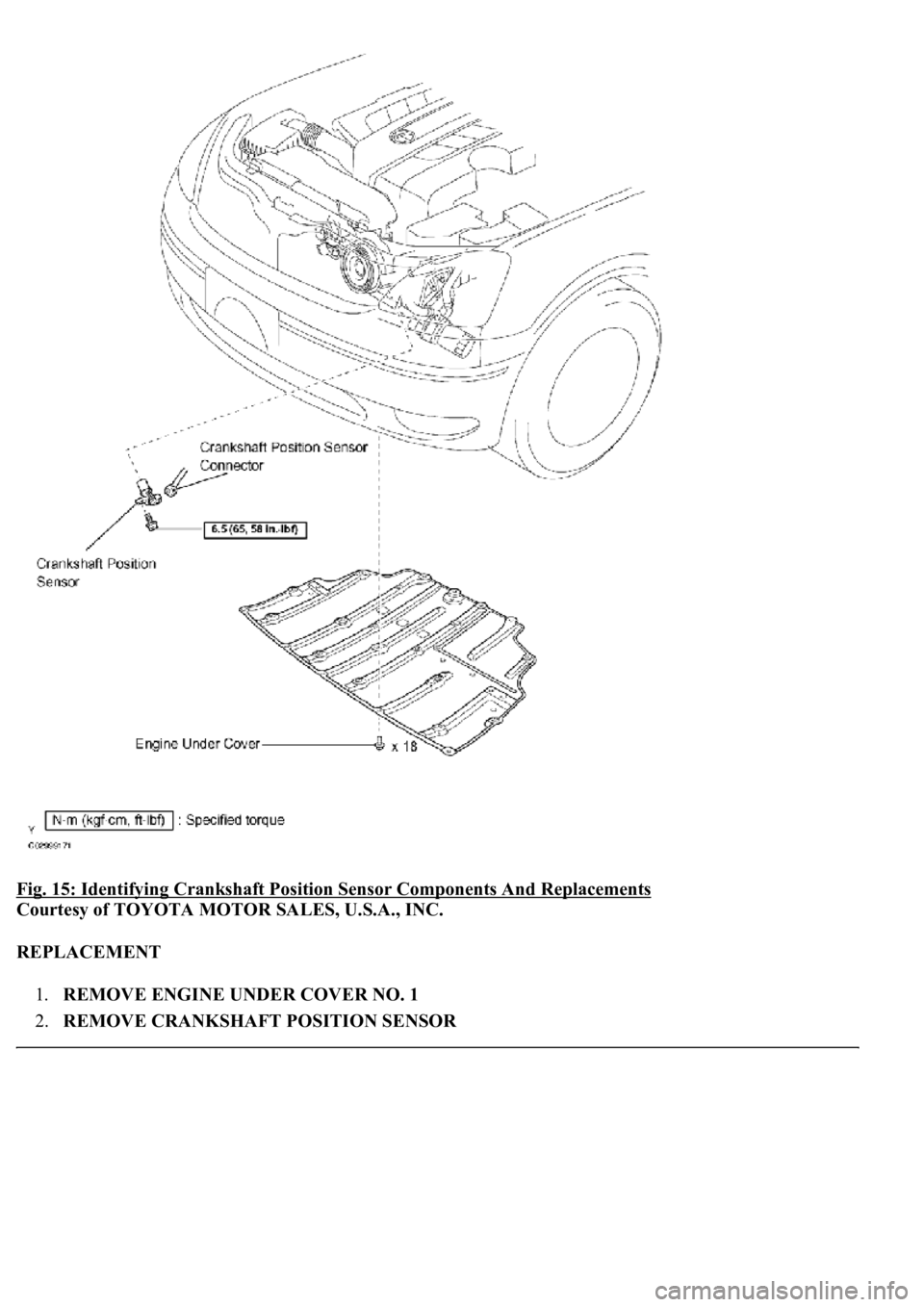
Fig. 15: Identifying Crankshaft Position Sensor Components And Replacements
Courtesy of TOYOTA MOTOR SALES, U.S.A., INC.
REPLACEMENT
1.REMOVE ENGINE UNDER COVER NO. 1
2.REMOVE CRANKSHAFT POSITION SENSOR
Page 4344 of 4500
a. Disconnect the sensor connector.
b. Remove the bolt and sensor.
Fig. 16: Removing Crankshaft Position Sensor
Courtesy of TOYOTA MOTOR SALES, U.S.A., INC.
3.INSTALL CRANKSHAFT POSITION SENSOR
a. Install a new sensor with the bolt.
Torque: 6.5 N.m (65 kgf.cm, 58 in.lbf)
b. Connect the sensor connector.
Page 4345 of 4500
4.INSTALL ENGINE UNDER COVER NO. 1
Page 4346 of 4500
Page 4347 of 4500
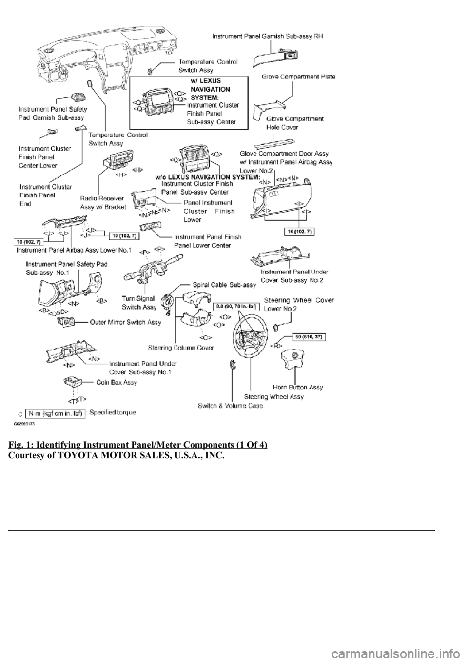
Fig. 1: Identifying Instrument Panel/Meter Components (1 Of 4)
Courtesy of TOYOTA MOTOR SALES, U.S.A., INC.
Page 4348 of 4500
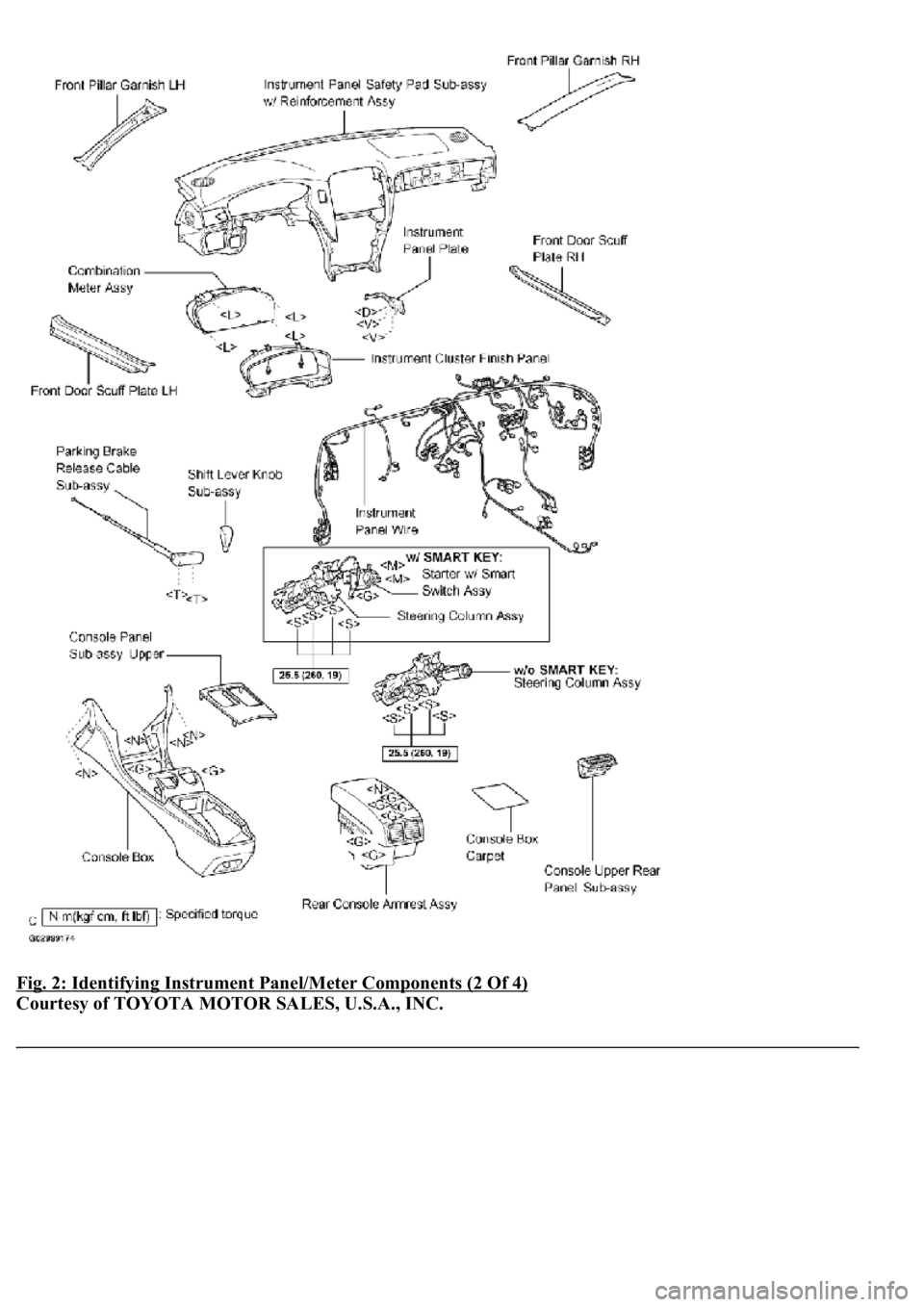
Fig. 2: Identifying Instrument Panel/Meter Components (2 Of 4)
Courtesy of TOYOTA MOTOR SALES, U.S.A., INC.
Page 4349 of 4500
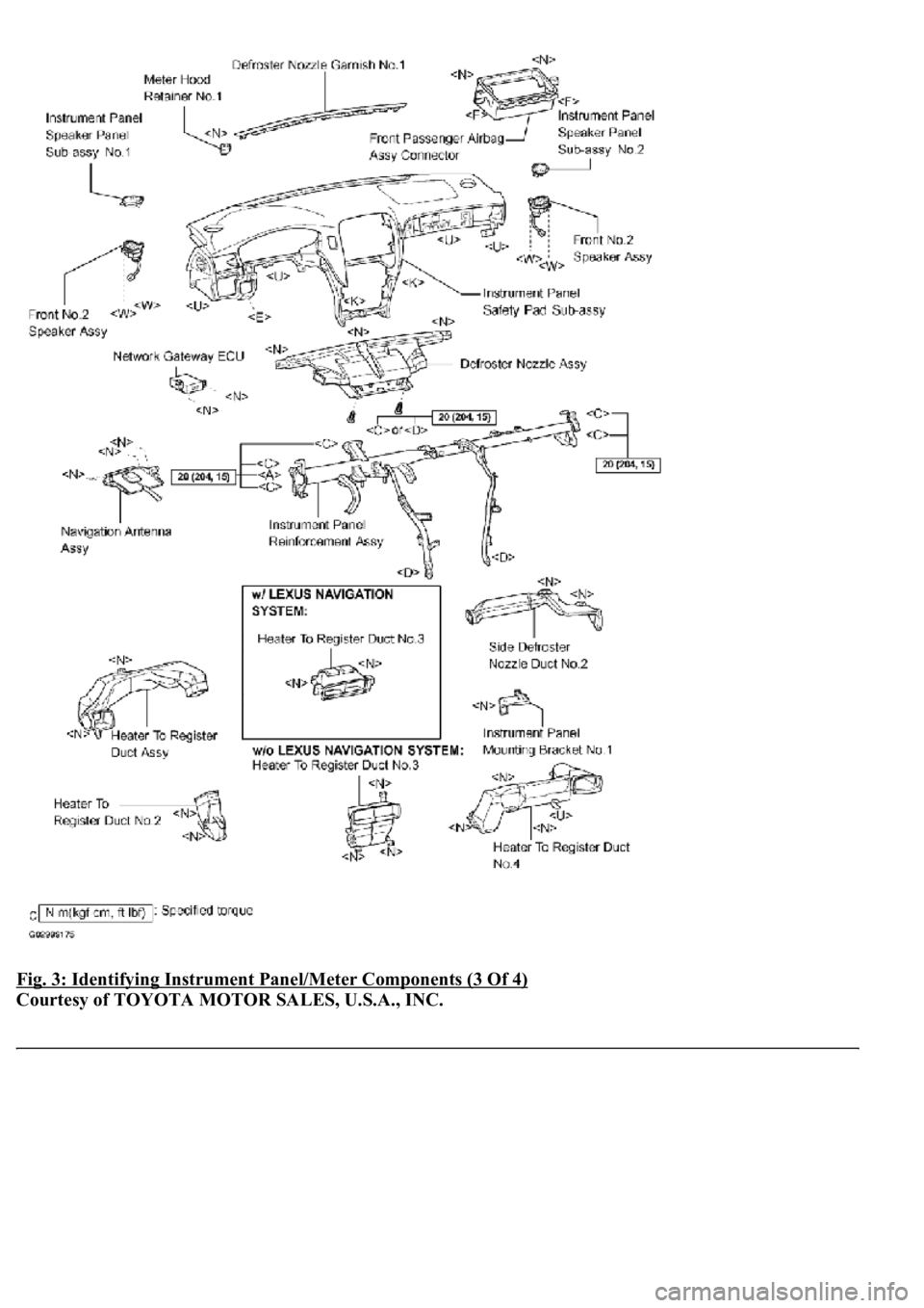
Fig. 3: Identifying Instrument Panel/Meter Components (3 Of 4)
Courtesy of TOYOTA MOTOR SALES, U.S.A., INC.
Page 4350 of 4500
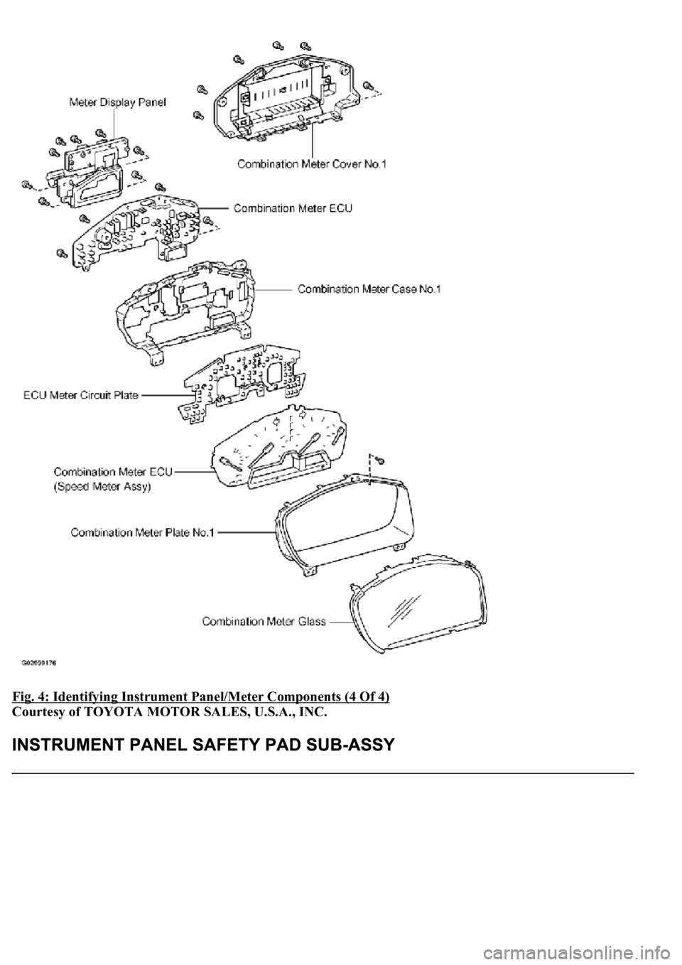
Fig. 4: Identifying Instrument Panel/Meter Components (4 Of 4)
Courtesy of TOYOTA MOTOR SALES, U.S.A., INC.
Trending: ECO mode, pcv, wheel bolts, automatic transmission, oil capacity, Manifold gasket, fuse diagram
