LEXUS LS430 2003 Factory Repair Manual
Manufacturer: LEXUS, Model Year: 2003,
Model line: LS430,
Model: LEXUS LS430 2003
Pages: 4500, PDF Size: 87.45 MB
LEXUS LS430 2003 Factory Repair Manual
LS430 2003
LEXUS
LEXUS
https://www.carmanualsonline.info/img/36/57050/w960_57050-0.png
LEXUS LS430 2003 Factory Repair Manual
Trending: engine oil, trunk, lock, recommended oil, mirror, c1336, tire size
Page 4351 of 4500
PRECAUTION
1. HANDLING PRECAUTIONS FOR STEERING SYSTEM
a. Care must be taken when replacing parts. Incorrect replacement could affect the performance of the
steering system and result in a driving hazard.
2. HANDLING PRECAUTIONS FOR SRS AIRBAG SYSTEM
a. The LS430 is equipped with SRS (Supplemental Restraint System) such as the driver airbag and
front passenger airbag, etc. Failure to carry out service operations in the correct sequence could
cause the SRS to unexpectedly deploy during servicing, possibly leading to a serious accident.
Before servicing (including removal or installation of parts, inspection or replacement), be sure to
read the precautionary notice for the supplemental restraint system (see PRECAUTION
).
REPLACEMENT
HINT:
COMPONENTS: SEE COMPONENTS
Installation is in the reverse order of removal.
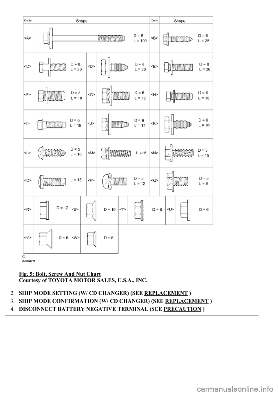
A bolt without a torque specification is shown in the standard bolt chart (see STANDARD BOLT ).
1. TABLE OF BOLT, SCREW AND NUT
HINT:
The bolts, screws and nuts, necessary for installation and removal of the instrument panel, are shown in
the illustration below with alphabet code.
Page 4352 of 4500
Fig. 5: Bolt, Screw And Nut Chart
Courtesy of TOYOTA MOTOR SALES, U.S.A., INC.
2.SHIP MODE SETTING (W/ CD CHANGER) (SEE REPLACEMENT
)
3.SHIP MODE CONFIRMATION (W/ CD CHANGER) (SEE REPLACEMENT
)
4.DISCONNECT BATTERY NEGATIVE TERMINAL (SEE PRECAUTION
)
Page 4353 of 4500
HINT:
Disconnect the battery negative terminal with the steering column assy extended.
Be sure to extend the steering column, otherwise the steering column cover cannot be removed.
5.PLACE FRONT WHEELS FACING STRAIGHT AHEAD
6.REMOVE SWITCH & VOLUME CASE (SEE OVERHAUL
)
7.REMOVE STEERING WHEEL COVER LOWER NO.2 (SEE OVERHAUL
)
8.REMOVE HORN BUTTON ASSY (SEE OVERHAUL
)
9.REMOVE STEERING WHEEL ASSY (SEE OVERHAUL
)
<00360036003700030013001c001c001800130010001800130013001400160003000b0013001c001c00180014001000130018001300140013000f00030013001c001c00180015001000130018001300140013000f00030013001c001c001800160010001300
18001300150013000f00030013001c001c0018001700100013[5021)
10.REMOVE STEERING COLUMN COVER (SEE OVERHAUL
)
11.REMOVE SPIRAL CABLE SUB-ASSY (SEE REPLACEMENT
)
12.REMOVE TURN SIGNAL SWITCH ASSY (SEE REPLACEMENT
)
13.REMOVE INSTRUMENT PANEL SAFETY PAD GARNISH SUB-ASSY
a. Using a screwdriver, disengage the upper/lower 2 claws inside the instrument panel safety pad
garnish sub-assy.
HINT:
Tape up the screwdriver tip before use.
Page 4354 of 4500
Fig. 6: Removing Instrument Panel Safety Pad Garnish Sub-Assy
Courtesy of TOYOTA MOTOR SALES, U.S.A., INC.
14.REMOVE INSTRUMENT CLUSTER FINISH PANEL CENTER LOWER
a. Using a screwdriver, disengage the 2 claws and remove the instrument cluster finish panel center
lower.
HINT:
Tape up the screwdriver tip before use.
Page 4355 of 4500
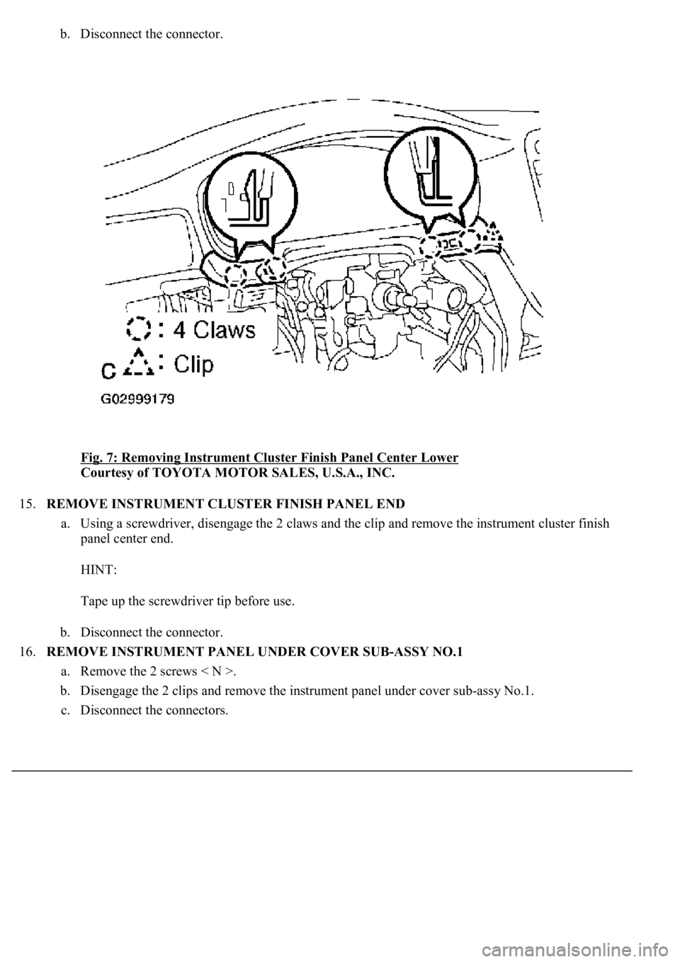
b. Disconnect the connector.
Fig. 7: Removing Instrument Cluster Finish Panel Center Lower
Courtesy of TOYOTA MOTOR SALES, U.S.A., INC.
15.REMOVE INSTRUMENT CLUSTER FINISH PANEL END
a. Using a screwdriver, disengage the 2 claws and the clip and remove the instrument cluster finish
panel center end.
HINT:
Tape up the screwdriver tip before use.
b. Disconnect the connector.
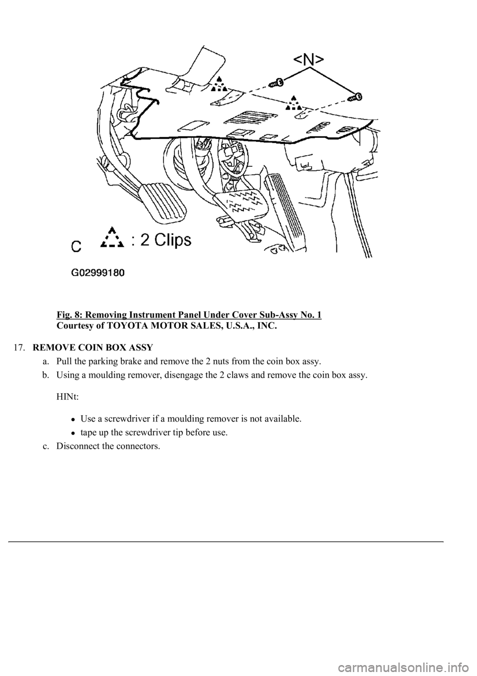
16.REMOVE INSTRUMENT PANEL UNDER COVER SUB-ASSY NO.1
a. Remove the 2 screws < N >.
b. Disengage the 2 clips and remove the instrument panel under cover sub-assy No.1.
c. Disconnect the connectors.
Page 4356 of 4500
Fig. 8: Removing Instrument Panel Under Cover Sub-Assy No. 1
Courtesy of TOYOTA MOTOR SALES, U.S.A., INC.
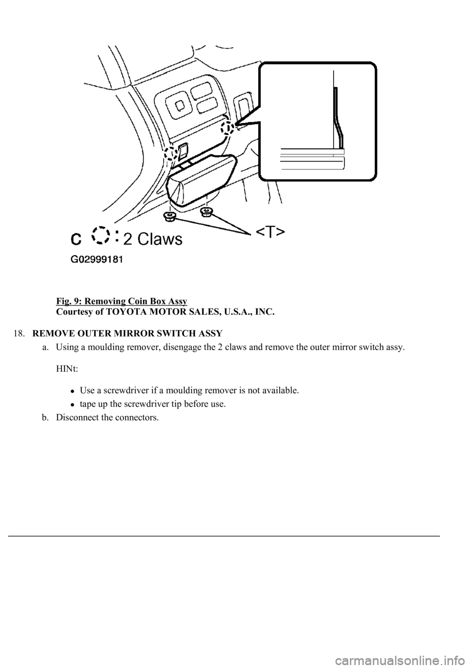
17.REMOVE COIN BOX ASSY
a. Pull the parking brake and remove the 2 nuts from the coin box assy.
b. Using a moulding remover, disengage the 2 claws and remove the coin box assy.
HINt:
Use a screwdriver if a moulding remover is not available.
tape up the screwdriver tip before use.
c. Disconnect the connectors.
Page 4357 of 4500
Fig. 9: Removing Coin Box Assy
Courtesy of TOYOTA MOTOR SALES, U.S.A., INC.
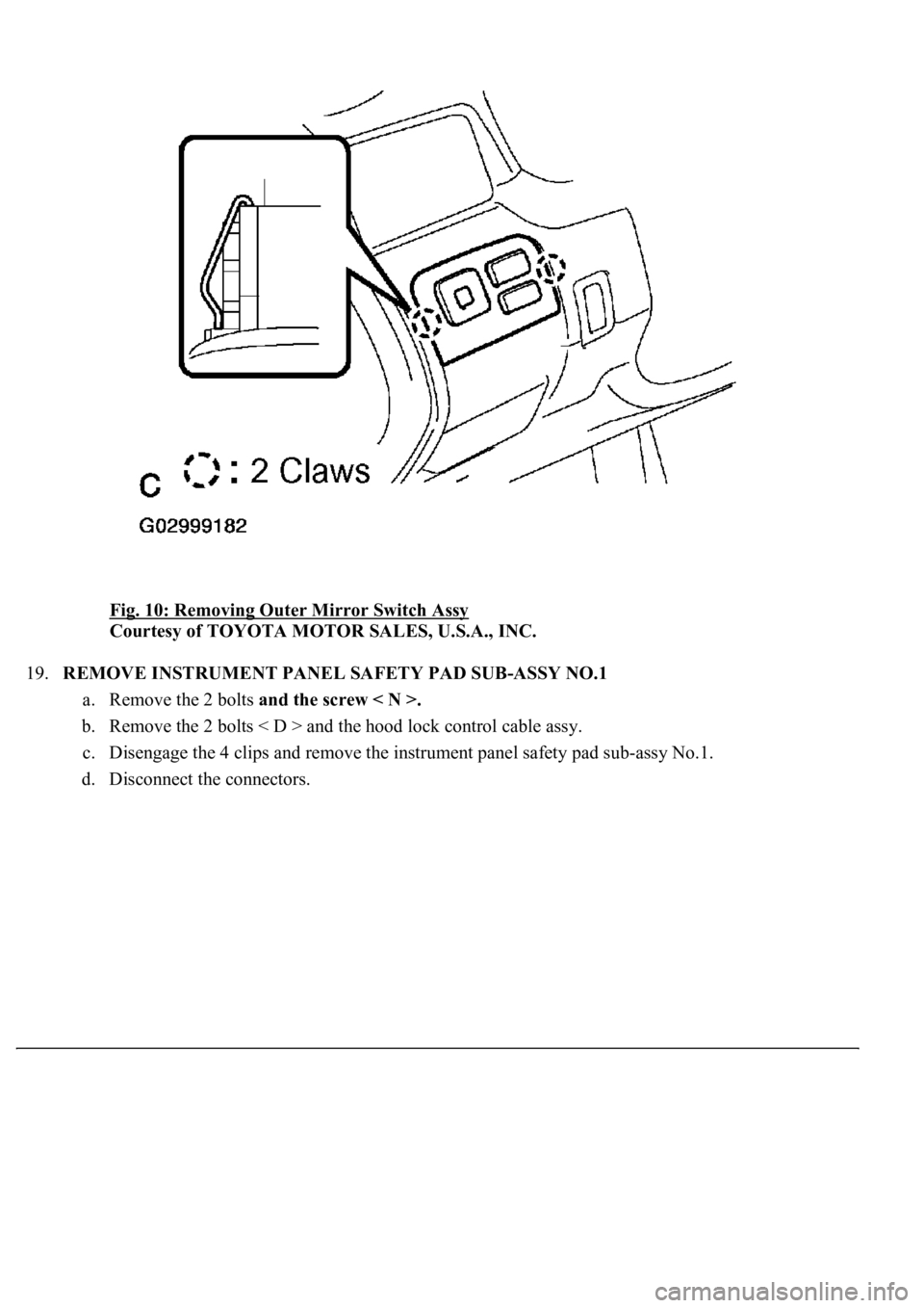
18.REMOVE OUTER MIRROR SWITCH ASSY
a. Using a moulding remover, disengage the 2 claws and remove the outer mirror switch assy.
HINt:
Use a screwdriver if a moulding remover is not available.
tape up the screwdriver tip before use.
b. Disconnect the connectors.
Page 4358 of 4500
Fig. 10: Removing Outer Mirror Switch Assy
Courtesy of TOYOTA MOTOR SALES, U.S.A., INC.
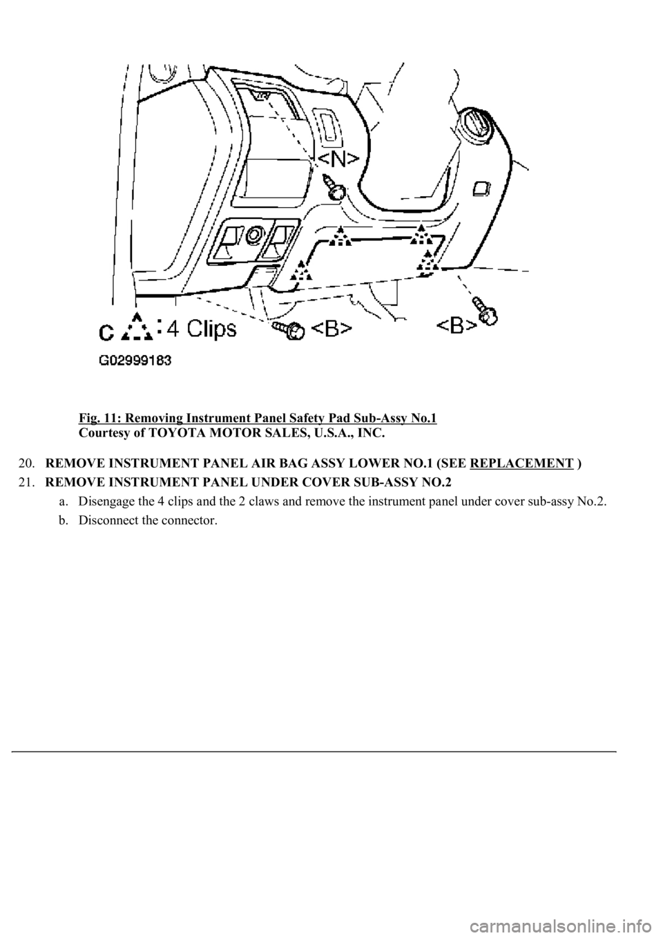
19.REMOVE INSTRUMENT PANEL SAFETY PAD SUB-ASSY NO.1
a. Remove the 2 bolts and the screw < N >.
b. Remove the 2 bolts < D > and the hood lock control cable assy.
c. Disengage the 4 clips and remove the instrument panel safety pad sub-assy No.1.
d. Disconnect the connectors.
Page 4359 of 4500
Fig. 11: Removing Instrument Panel Safety Pad Sub-Assy No.1
Courtesy of TOYOTA MOTOR SALES, U.S.A., INC.
20.REMOVE INSTRUMENT PANEL AIR BAG ASSY LOWER NO.1 (SEE REPLACEMENT
)
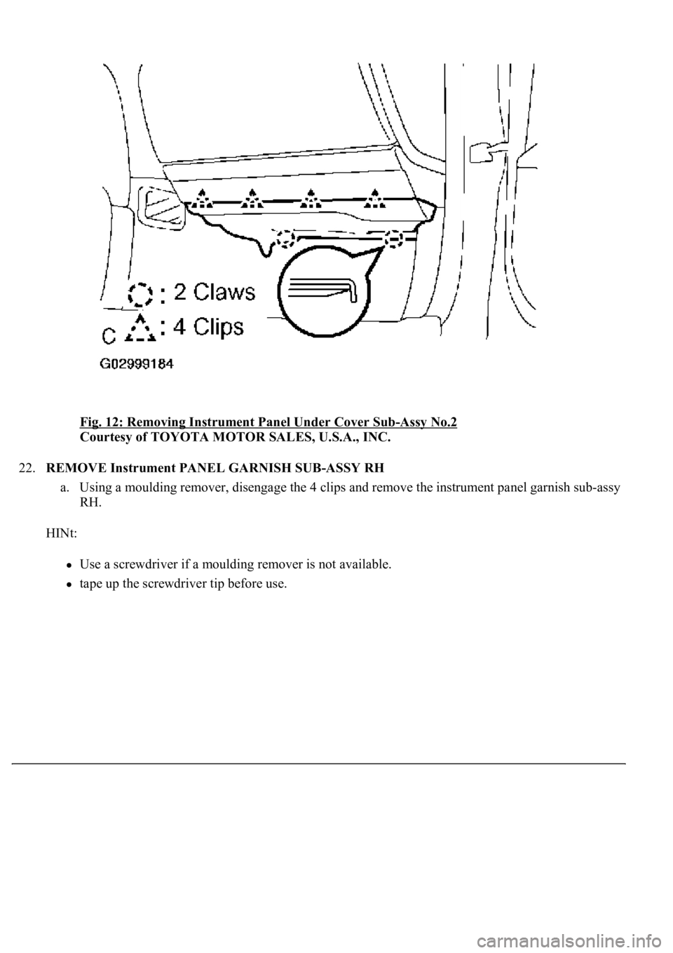
21.REMOVE INSTRUMENT PANEL UNDER COVER SUB-ASSY NO.2
a. Disengage the 4 clips and the 2 claws and remove the instrument panel under cover sub-assy No.2.
b. Disconnect the connector.
Page 4360 of 4500
Fig. 12: Removing Instrument Panel Under Cover Sub-Assy No.2
Courtesy of TOYOTA MOTOR SALES, U.S.A., INC.
22.REMOVE Instrument PANEL GARNISH SUB-ASSY RH
a. Using a moulding remover, disengage the 4 clips and remove the instrument panel garnish sub-assy
RH.
HINt:
Use a screwdriver if a moulding remover is not available.
tape up the screwdriver tip before use.
Trending: brake, hood release, oil, brake pads, fuel system, water pump, actuator damper

