LEXUS LS430 2003 Factory Repair Manual
Manufacturer: LEXUS, Model Year: 2003,
Model line: LS430,
Model: LEXUS LS430 2003
Pages: 4500, PDF Size: 87.45 MB
LEXUS LS430 2003 Factory Repair Manual
LS430 2003
LEXUS
LEXUS
https://www.carmanualsonline.info/img/36/57050/w960_57050-0.png
LEXUS LS430 2003 Factory Repair Manual
Trending: warning lights, Navi, steering interlock cable, remove seats, fuel cap, relay, horn
Page 441 of 4500
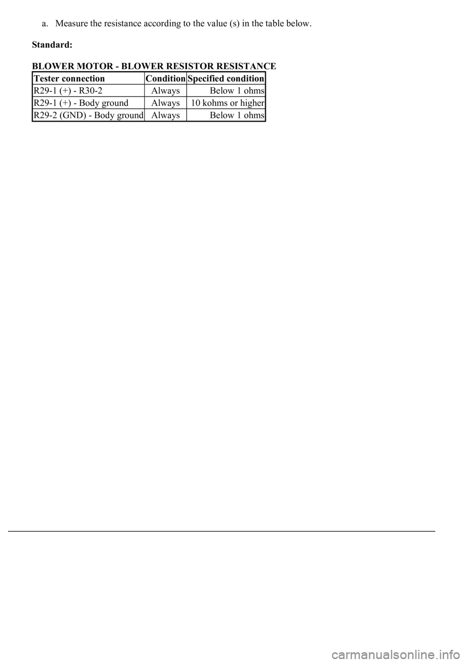
a. Measure the resistance according to the value (s) in the table below.
Standard:
BLOWER MOTOR - BLOWER RESISTOR RESISTANCE
Tester connectionConditionSpecified condition
R29-1 (+) - R30-2AlwaysBelow 1 ohms
R29-1 (+) - Body groundAlways10 kohms or higher
R29-2 (GND) - Body groundAlwaysBelow 1 ohms
Page 442 of 4500
Page 443 of 4500
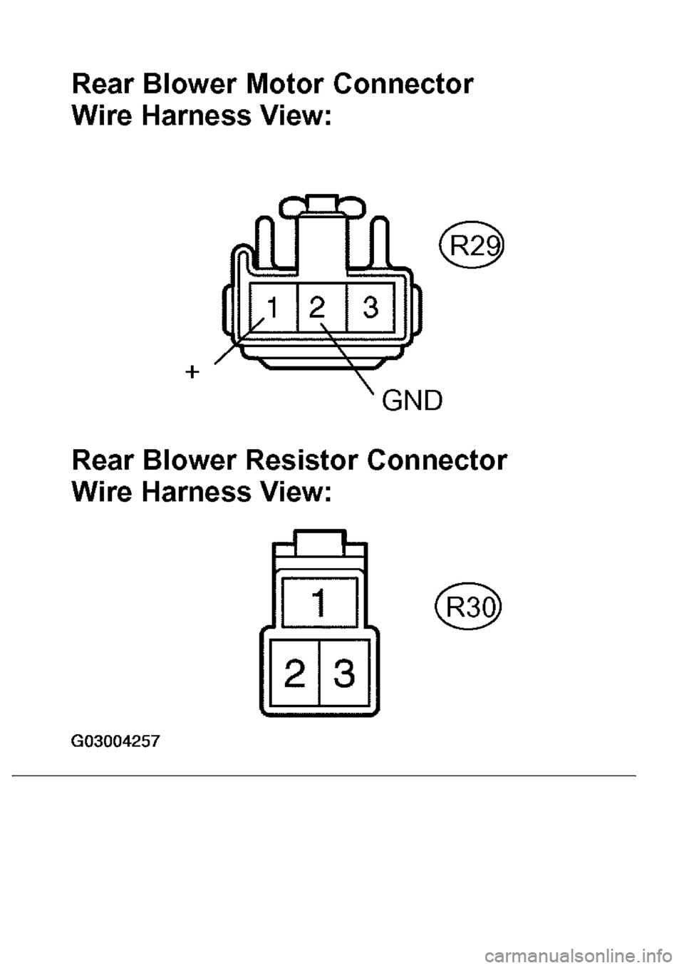
Fig. 180: Checking Harness And Connector (Blower Motor -Blower Resistor)
Courtesy of TOYOTA MOTOR SALES, U.S.A., INC.
NG: REPLACE OR REPLACE HARNESS OR CONNECTOR
REPLACE REAR AIR CONDITIONING AMPLIFIER (SEE OVERHAUL
)
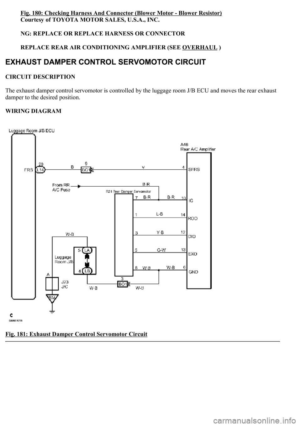
CIRCUIT DESCRIPTION
The exhaust damper control servomotor is controlled by the luggage room J/B ECU and moves the rear exhaust
damper to the desired position.
WIRING DIAGRAM
Fig. 181: Exhaust Damper Control Servomotor Circuit
Page 444 of 4500
Courtesy of TOYOTA MOTOR SALES, U.S.A., INC.
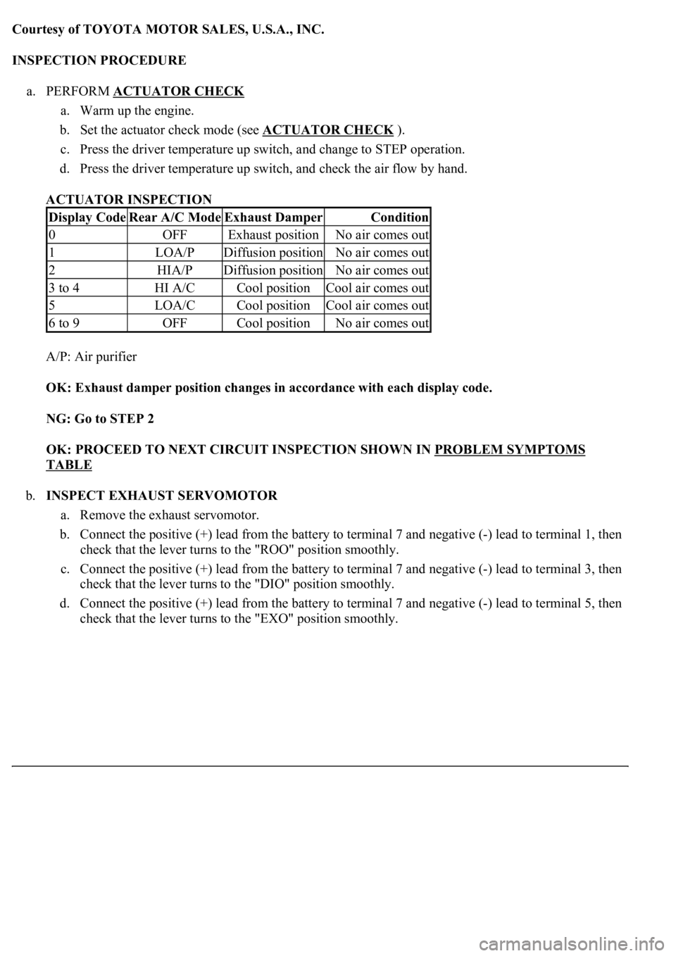
INSPECTION PROCEDURE
a. PERFORM ACTUATOR CHECK
a. Warm up the engine.
b. Set the actuator check mode (see ACTUATOR CHECK
).
c. Press the driver temperature up switch, and change to STEP operation.
d. Press the driver temperature up switch, and check the air flow by hand.
ACTUATOR INSPECTION
A/P: Air purifier
OK: Exhaust damper position changes in accordance with each display code.
NG: Go to STEP 2
OK: PROCEED TO NEXT CIRCUIT INSPECTION SHOWN IN PROBLEM SYMPTOMS
TABLE
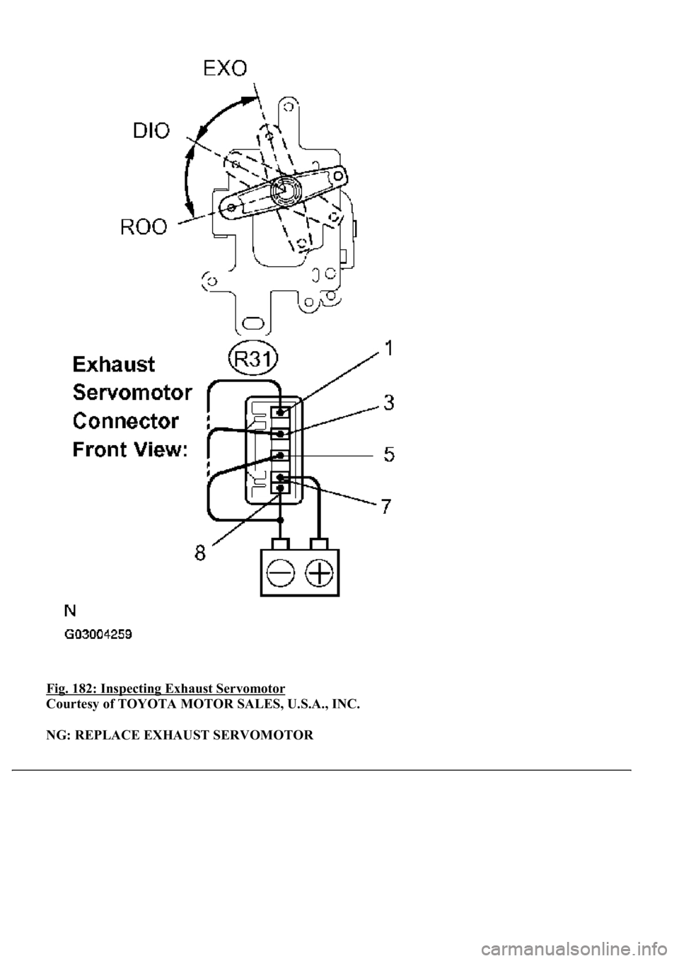
b.INSPECT EXHAUST SERVOMOTOR
a. Remove the exhaust servomotor.
b. Connect the positive (+) lead from the battery to terminal 7 and negative (-) lead to terminal 1, then
check that the lever turns to the "ROO" position smoothly.
c. Connect the positive (+) lead from the battery to terminal 7 and negative (-) lead to terminal 3, then
check that the lever turns to the "DIO" position smoothly.
d. Connect the positive (+) lead from the battery to terminal 7 and negative (-) lead to terminal 5, then
check that the lever turns to the "EXO" position smoothl
y.
Display CodeRear A/C ModeExhaust DamperCondition
0OFFExhaust positionNo air comes out
1LOA/PDiffusion positionNo air comes out
2HIA/PDiffusion positionNo air comes out
3 to 4HI A/CCool positionCool air comes out
5LOA/CCool positionCool air comes out
6 to 9OFFCool positionNo air comes out
Page 445 of 4500
Fig. 182: Inspecting Exhaust Servomotor
Courtesy of TOYOTA MOTOR SALES, U.S.A., INC.
NG: REPLACE EXHAUST SERVOMOTOR
Page 446 of 4500
OK: Go to next step
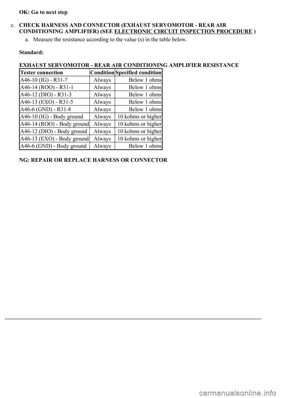
c.CHECK HARNESS AND CONNECTOR (EXHAUST SERVOMOTOR - REAR AIR
CONDITIONING AMPLIFIER) (SEE ELECTRONIC CIRCUIT INSPECTION PROCEDURE
)
a. Measure the resistance according to the value (s) in the table below.
Standard:
EXHAUST SERVOMOTOR - REAR AIR CONDITIONING AMPLIFIER RESISTANCE
NG: REPAIR OR REPLACE HARNESS OR CONNECTOR
Tester connectionConditionSpecified condition
A46-10 (IG) - R31-7AlwaysBelow 1 ohms
A46-14 (ROO) - R31-1AlwaysBelow 1 ohms
A46-12 (DIO) - R31-3AlwaysBelow 1 ohms
A46-13 (EXO) - R31-5AlwaysBelow 1 ohms
A46-6 (GND) - R31-8AlwaysBelow 1 ohms
A46-10 (IG) - Body groundAlways10 kohms or higher
A46-14 (ROO) - Body groundAlways10 kohms or higher
A46-12 (DIO) - Body groundAlways10 kohms or higher
A46-13 (EXO) - Body groundAlways10 kohms or higher
A46-6 (GND) - Body groundAlwaysBelow 1 ohms
Page 447 of 4500
Page 448 of 4500
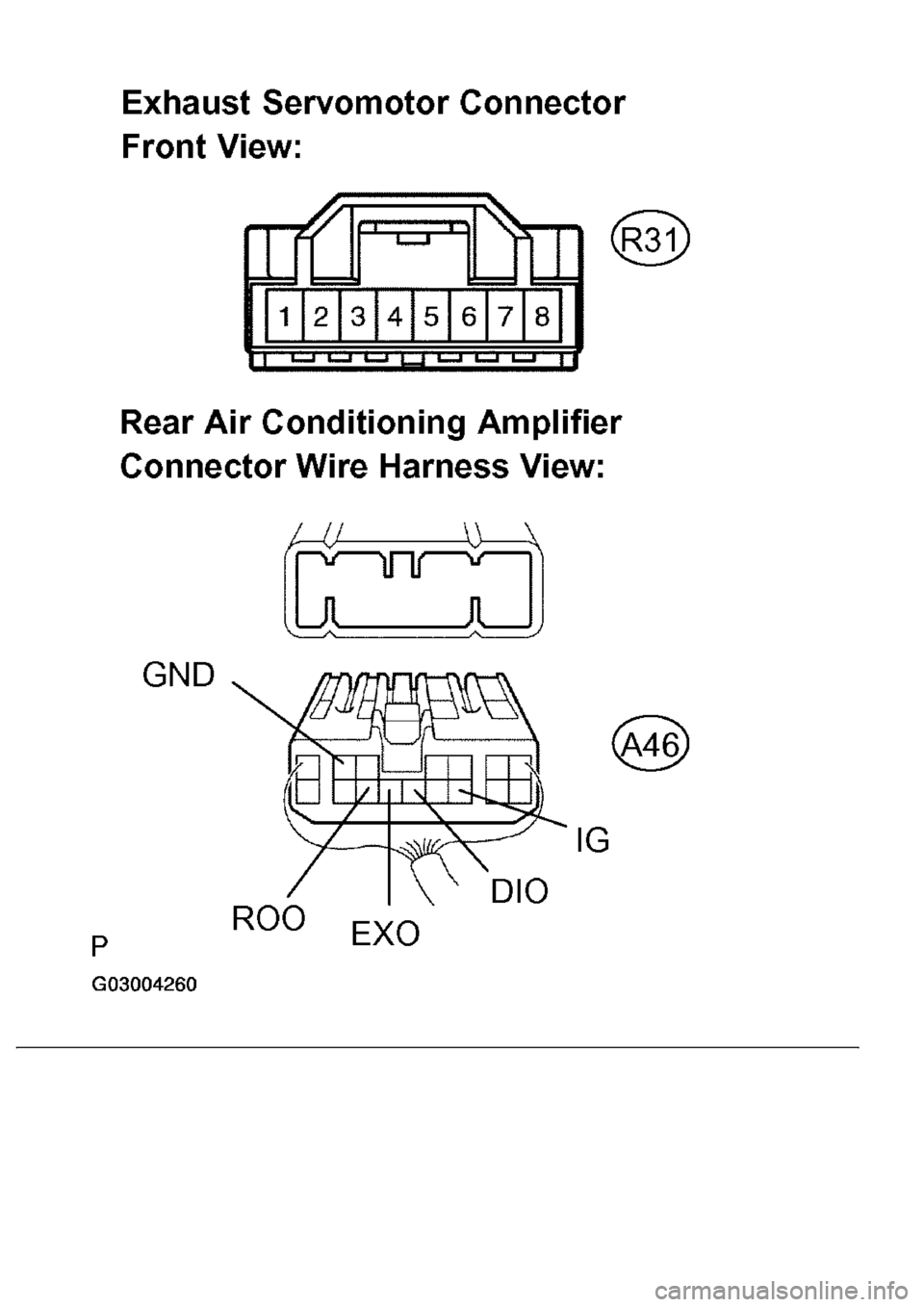
Fig. 183: Checking Harness And Connector (Exhaust Servomotor -Rear Air Conditioning
Amplifier)
Courtesy of TOYOTA MOTOR SALES, U.S.A., INC.
OK: REPLACE REAR AIR CONDITIONING AMPLIFIER (SEE OVERHAUL
)
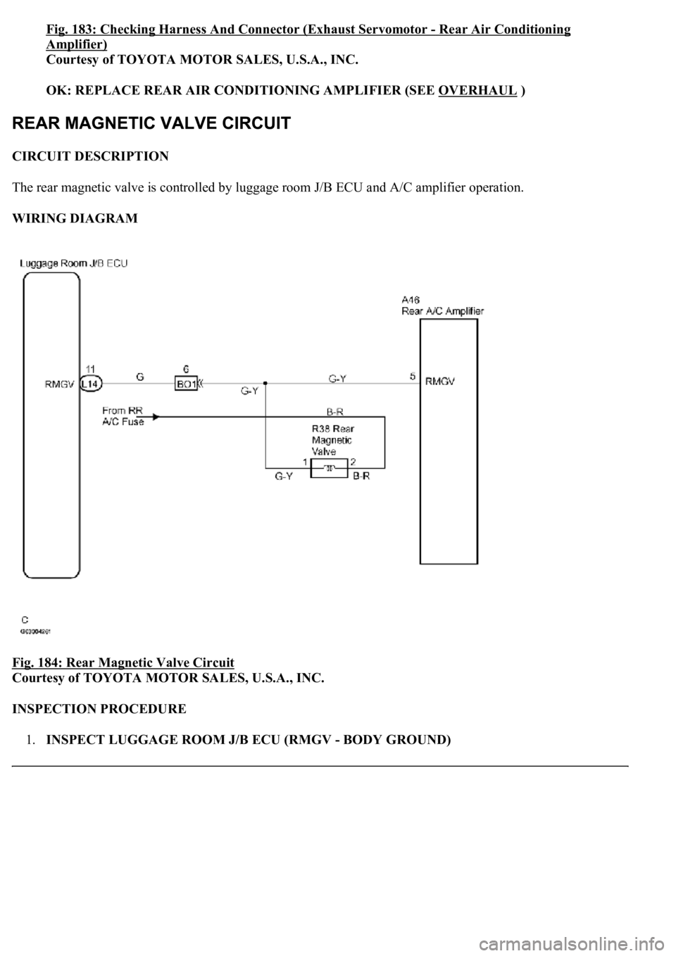
CIRCUIT DESCRIPTION
The rear magnetic valve is controlled by luggage room J/B ECU and A/C amplifier operation.
WIRING DIAGRAM
Fig. 184: Rear Magnetic Valve Circuit
Courtesy of TOYOTA MOTOR SALES, U.S.A., INC.
INSPECTION PROCEDURE
1.INSPECT LUGGAGE ROOM J/B ECU (RMGV - BODY GROUND)
Page 449 of 4500
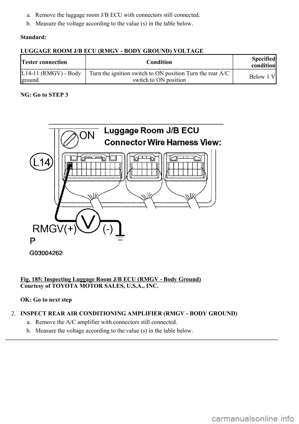
a. Remove the luggage room J/B ECU with connectors still connected.
b. Measure the voltage according to the value (s) in the table below.
Standard:
LUGGAGE ROOM J/B ECU (RMGV - BODY GROUND) VOLTAGE
NG: Go to STEP 3
Fig. 185: Inspecting Luggage Room J/B ECU (RMGV
- Body Ground)
Courtesy of TOYOTA MOTOR SALES, U.S.A., INC.
OK: Go to next step
2.INSPECT REAR AIR CONDITIONING AMPLIFIER (RMGV - BODY GROUND)
a. Remove the A/C amplifier with connectors still connected.
b. Measure the voltage according to the value (s) in the table below.
Tester connectionConditionSpecified
condition
L14-11 (RMGV) - Body
groundTurn the ignition switch to ON position Turn the rear A/C
switch to ON positionBelow 1 V
Page 450 of 4500
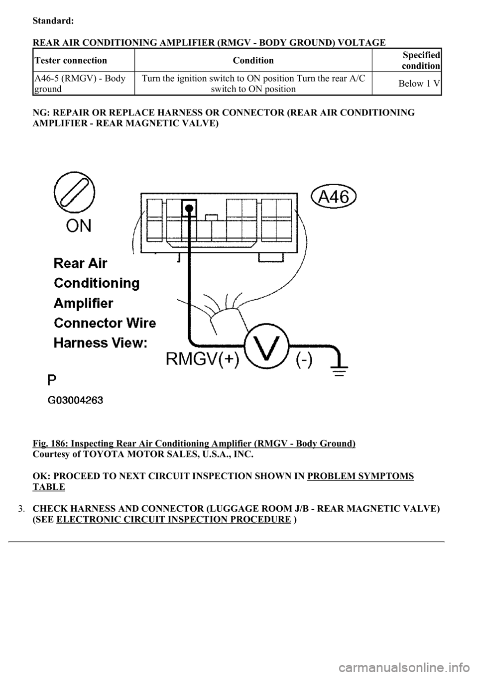
Standard:
REAR AIR CONDITIONING AMPLIFIER (RMGV - BODY GROUND) VOLTAGE
NG: REPAIR OR REPLACE HARNESS OR CONNECTOR (REAR AIR CONDITIONING
AMPLIFIER - REAR MAGNETIC VALVE)
Fig. 186: Inspecting Rear Air Conditioning Amplifier (RMGV
- Body Ground)
Courtesy of TOYOTA MOTOR SALES, U.S.A., INC.
OK: PROCEED TO NEXT CIRCUIT INSPECTION SHOWN IN PROBLEM SYMPTOMS
TABLE
3.CHECK HARNESS AND CONNECTOR (LUGGAGE ROOM J/B - REAR MAGNETIC VALVE)
(SEE ELECTRONIC CIRCUIT INSPECTION PROCEDURE
)
Tester connectionConditionSpecified
condition
A46-5 (RMGV) - Body
groundTurn the ignition switch to ON position Turn the rear A/C
switch to ON positionBelow 1 V
Trending: suspension, park assist, Door lock actuator, rear seat, CD changer, fuel filter location, traction control
