LEXUS LS430 2003 Factory Repair Manual
Manufacturer: LEXUS, Model Year: 2003,
Model line: LS430,
Model: LEXUS LS430 2003
Pages: 4500, PDF Size: 87.45 MB
LEXUS LS430 2003 Factory Repair Manual
LS430 2003
LEXUS
LEXUS
https://www.carmanualsonline.info/img/36/57050/w960_57050-0.png
LEXUS LS430 2003 Factory Repair Manual
Trending: ABS, Manifold gasket, snow chains, oil type, Signal compressor condition, Driver side vent, instrument panel
Page 621 of 4500
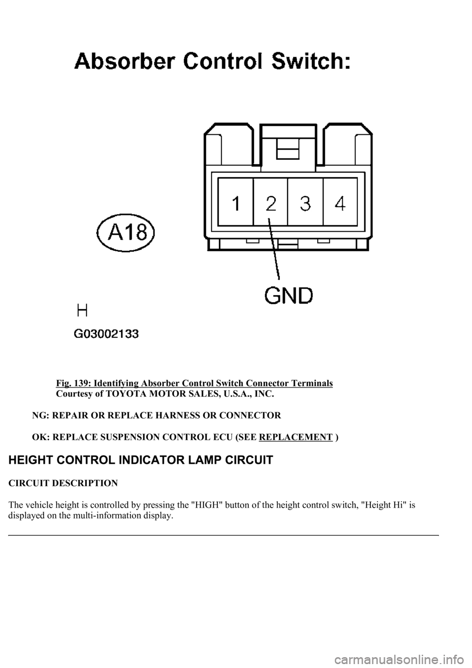
Fig. 139: Identifying Absorber Control Switch Connector Terminals
Courtesy of TOYOTA MOTOR SALES, U.S.A., INC.
NG: REPAIR OR REPLACE HARNESS OR CONNECTOR
OK: REPLACE SUSPENSION CONTROL ECU (SEE REPLACEMENT
)
CIRCUIT DESCRIPTION
The vehicle height is controlled by pressing the "HIGH" button of the height control switch, "Height Hi" is
displayed on the multi-information display.
Page 622 of 4500
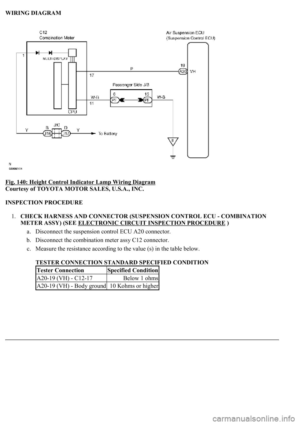
WIRING DIAGRAM
Fig. 140: Height Control Indicator Lamp Wiring Diagram
Courtesy of TOYOTA MOTOR SALES, U.S.A., INC.
INSPECTION PROCEDURE
1.CHECK HARNESS AND CONNECTOR (SUSPENSION CONTROL ECU - COMBINATION
METER ASSY) (SEE ELECTRONIC CIRCUIT INSPECTION PROCEDURE
)
a. Disconnect the suspension control ECU A20 connector.
b. Disconnect the combination meter assy C12 connector.
c. Measure the resistance according to the value (s) in the table below.
TESTER CONNECTION STANDARD SPECIFIED CONDITION
Tester ConnectionSpecified Condition
A20-19 (VH) - C12-17Below 1 ohms
A20-19 (VH) - Body ground10 Kohms or higher
Page 623 of 4500
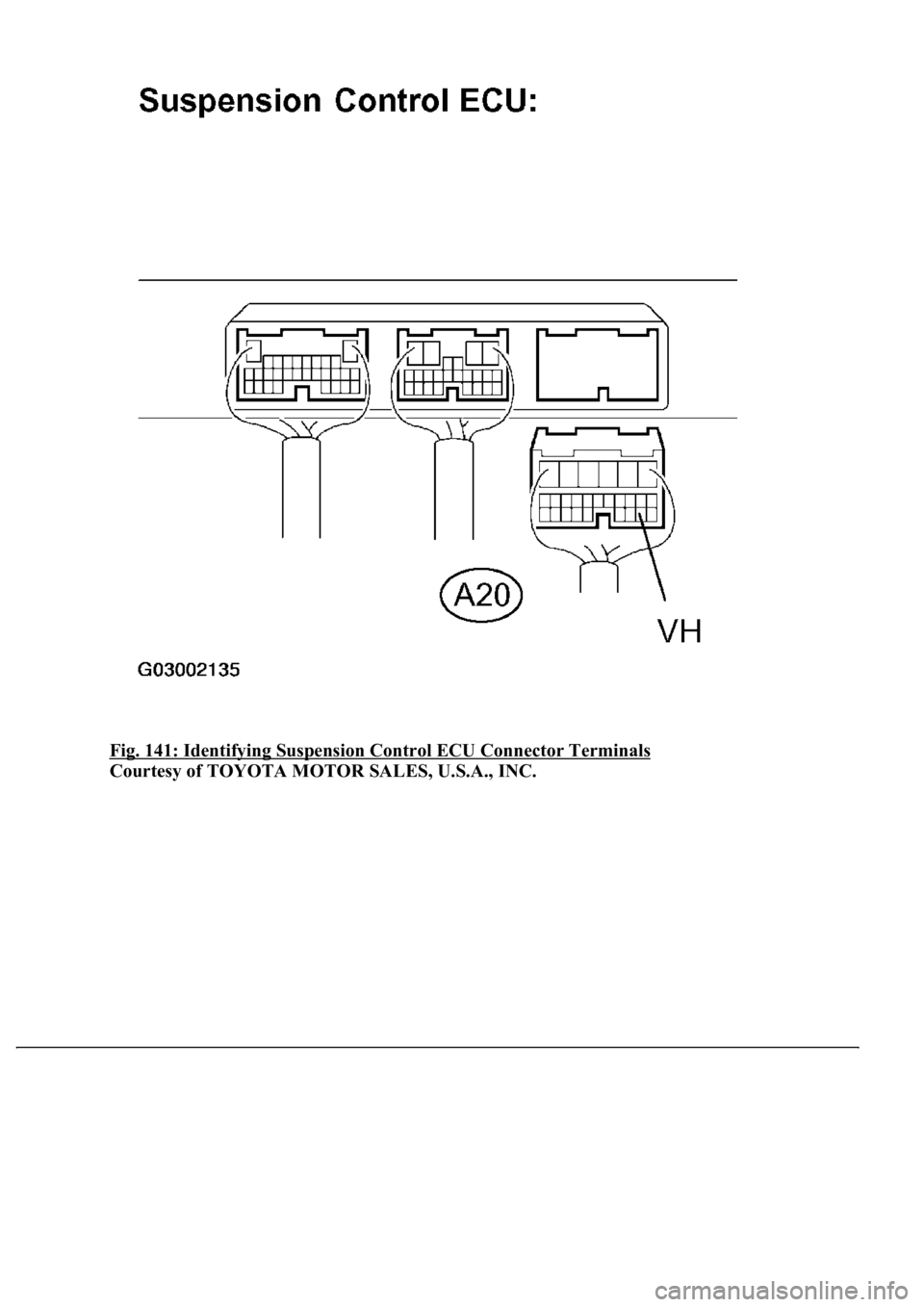
Fig. 141: Identifying Suspension Control ECU Connector Terminals
Courtesy of TOYOTA MOTOR SALES, U.S.A., INC.
Page 624 of 4500
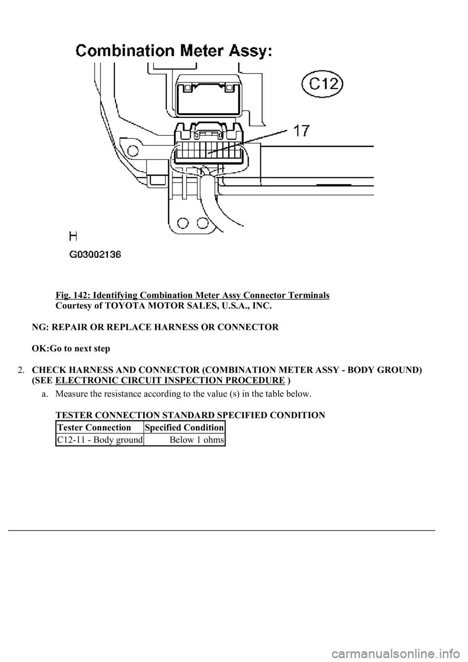
Fig. 142: Identifying Combination Meter Assy Connector Terminals
Courtesy of TOYOTA MOTOR SALES, U.S.A., INC.
NG: REPAIR OR REPLACE HARNESS OR CONNECTOR
OK:Go to next step
2.CHECK HARNESS AND CONNECTOR (COMBINATION METER ASSY - BODY GROUND)
(SEE ELECTRONIC CIRCUIT INSPECTION PROCEDURE
)
a. Measure the resistance according to the value (s) in the table below.
TESTER CONNECTION STANDARD SPECIFIED CONDITION
Tester ConnectionSpecified Condition
C12-11 - Body groundBelow 1 ohms
Page 625 of 4500
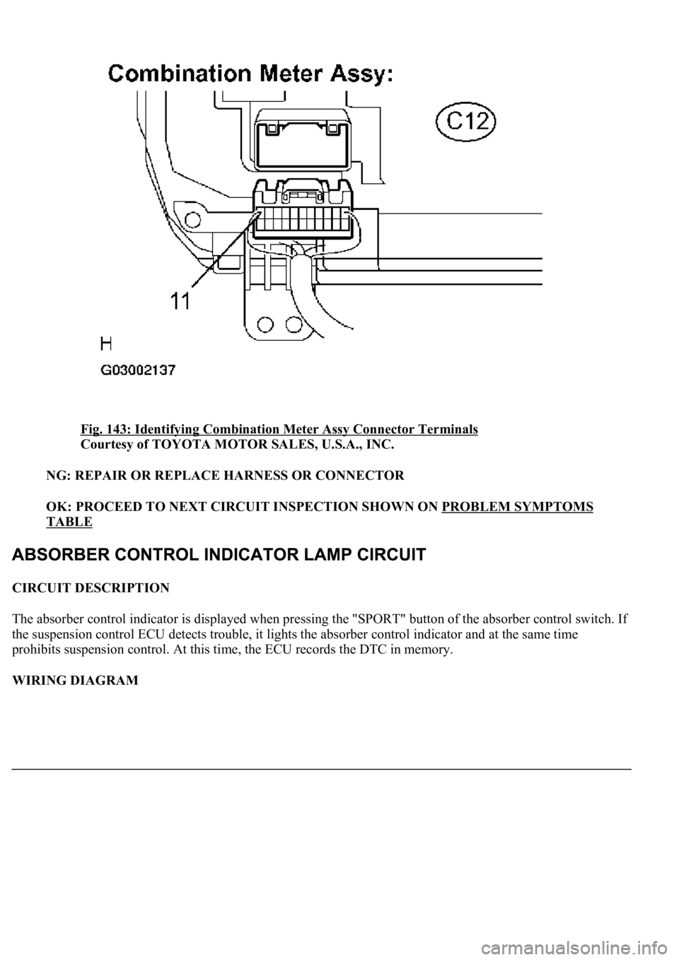
Fig. 143: Identifying Combination Meter Assy Connector Terminals
Courtesy of TOYOTA MOTOR SALES, U.S.A., INC.
NG: REPAIR OR REPLACE HARNESS OR CONNECTOR
OK: PROCEED TO NEXT CIRCUIT INSPECTION SHOWN ON PROBLEM SYMPTOMS
TABLE
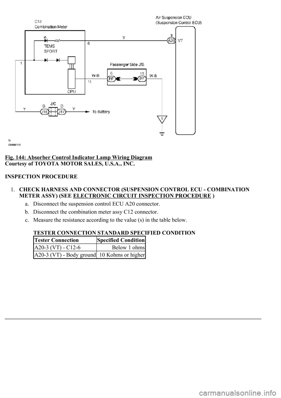
CIRCUIT DESCRIPTION
The absorber control indicator is displayed when pressing the "SPORT" button of the absorber control switch. I
f
the suspension control ECU detects trouble, it lights the absorber control indicator and at the same time
prohibits suspension control. At this time, the ECU records the DTC in memory.
WIRING DIAGRAM
Page 626 of 4500
<0029004c004a00110003001400170017001d0003002400450056005200550045004800550003002600520051005700550052004f0003002c00510047004c004600440057005200550003002f0044005000530003003a004c0055004c0051004a0003002700
4c0044004a005500440050[
Courtesy of TOYOTA MOTOR SALES, U.S.A., INC.
INSPECTION PROCEDURE
1.CHECK HARNESS AND CONNECTOR (SUSPENSION CONTROL ECU - COMBINATION
METER ASSY) (SEE ELECTRONIC CIRCUIT INSPECTION PROCEDURE
)
a. Disconnect the suspension control ECU A20 connector.
b. Disconnect the combination meter assy C12 connector.
c. Measure the resistance according to the value (s) in the table below.
TESTER CONNECTION STANDARD SPECIFIED CONDITION
Tester ConnectionSpecified Condition
A20-3 (VT) - C12-6Below 1 ohms
A20-3 (VT) - Body ground10 Kohms or higher
Page 627 of 4500
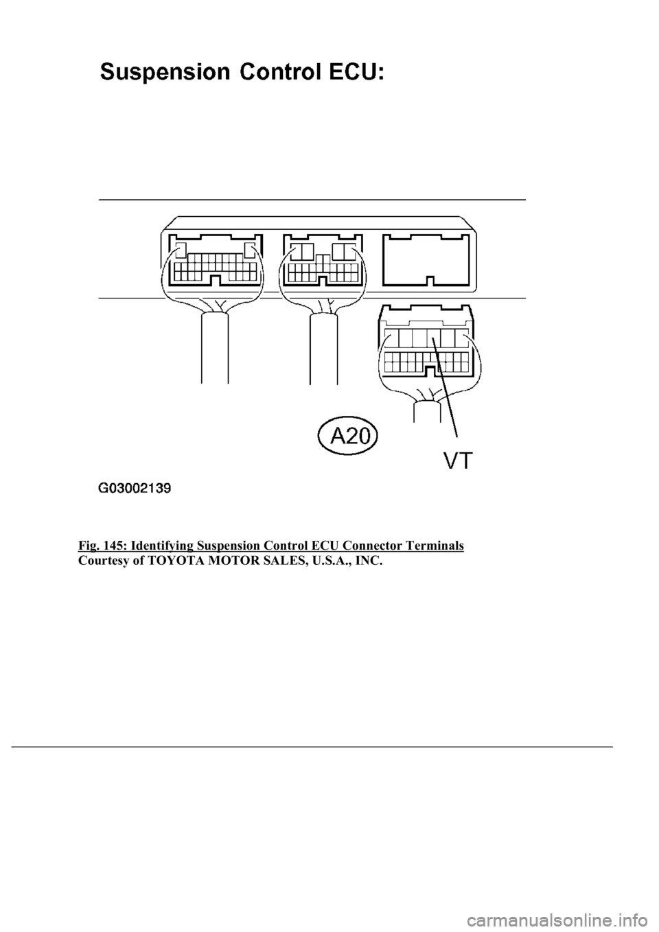
Fig. 145: Identifying Suspension Control ECU Connector Terminals
Courtesy of TOYOTA MOTOR SALES, U.S.A., INC.
Page 628 of 4500
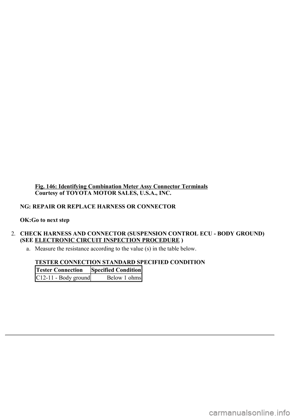
Fig. 146: Identifying Combination Meter Assy Connector Terminals
Courtesy of TOYOTA MOTOR SALES, U.S.A., INC.
NG: REPAIR OR REPLACE HARNESS OR CONNECTOR
OK:Go to next step
2.CHECK HARNESS AND CONNECTOR (SUSPENSION CONTROL ECU - BODY GROUND)
(SEE ELECTRONIC CIRCUIT INSPECTION PROCEDURE
)
a. Measure the resistance according to the value (s) in the table below.
TESTER CONNECTION STANDARD SPECIFIED CONDITION
Tester ConnectionSpecified Condition
C12-11 - Body groundBelow 1 ohms
Page 629 of 4500
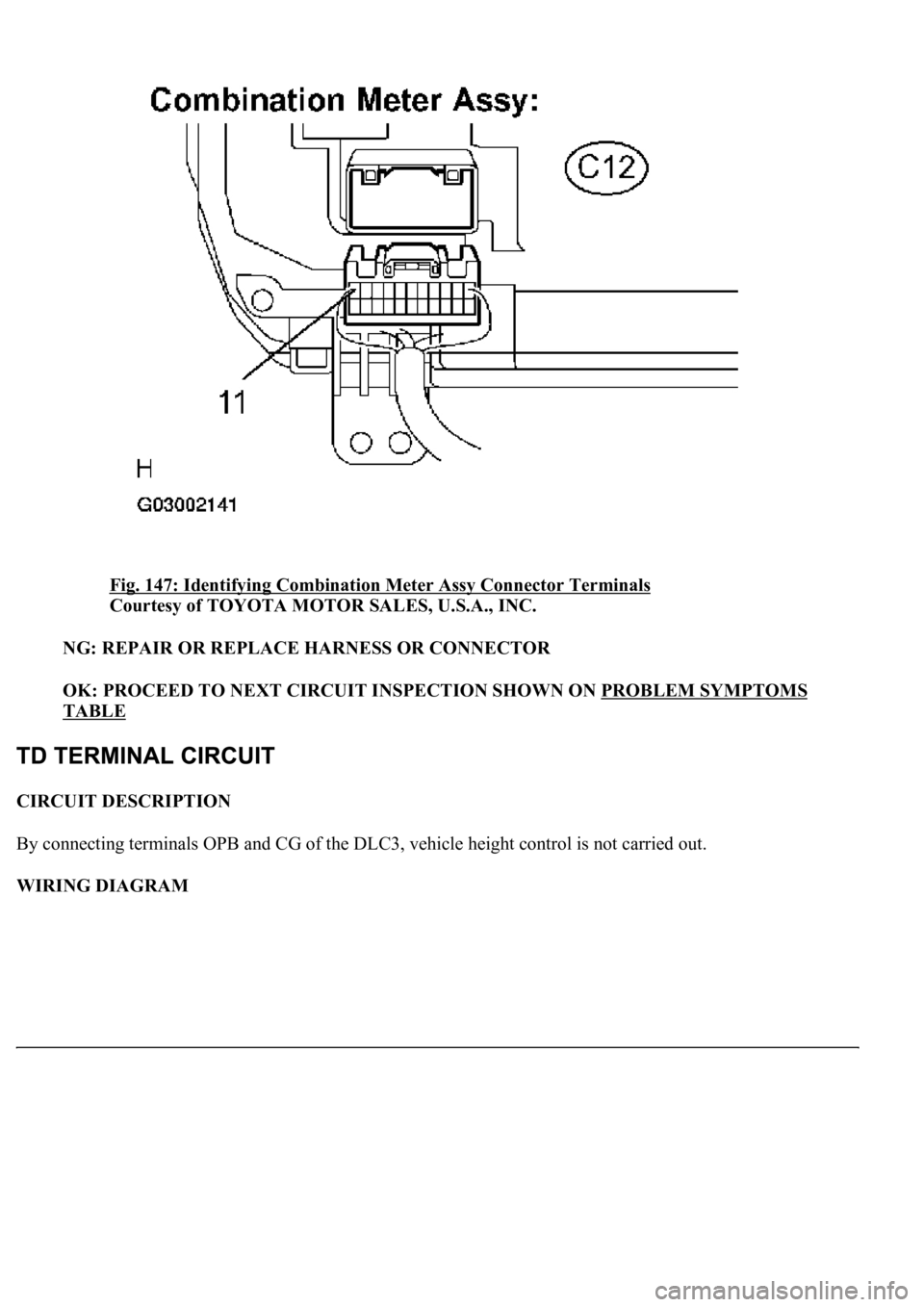
Fig. 147: Identifying Combination Meter Assy Connector Terminals
Courtesy of TOYOTA MOTOR SALES, U.S.A., INC.
NG: REPAIR OR REPLACE HARNESS OR CONNECTOR
OK: PROCEED TO NEXT CIRCUIT INSPECTION SHOWN ON PROBLEM SYMPTOMS
TABLE
CIRCUIT DESCRIPTION
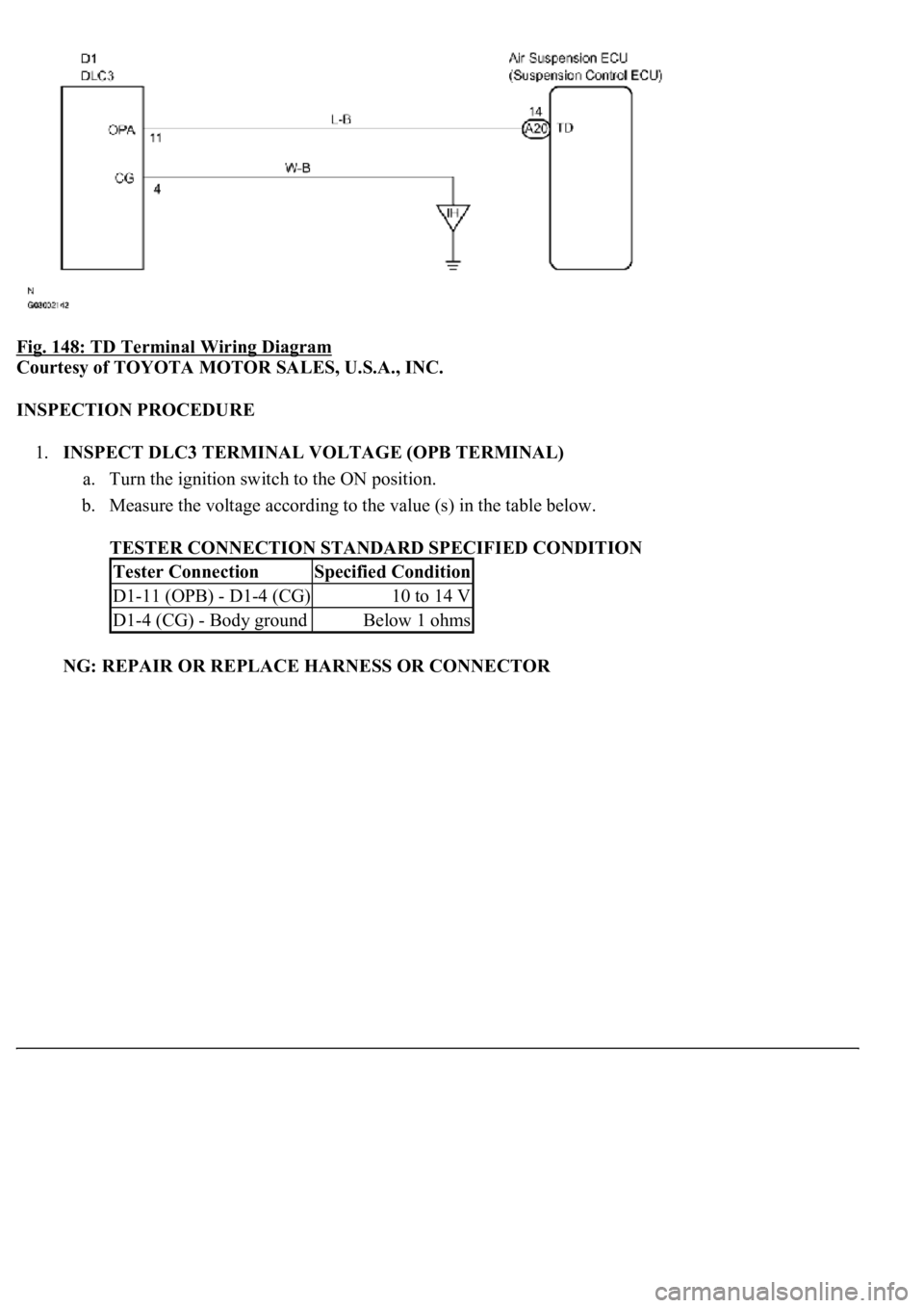
By connecting terminals OPB and CG of the DLC3, vehicle height control is not carried out.
WIRING DIAGRAM
Page 630 of 4500
Fig. 148: TD Terminal Wiring Diagram
Courtesy of TOYOTA MOTOR SALES, U.S.A., INC.
INSPECTION PROCEDURE
1.INSPECT DLC3 TERMINAL VOLTAGE (OPB TERMINAL)
a. Turn the ignition switch to the ON position.
b. Measure the voltage according to the value (s) in the table below.
TESTER CONNECTION STANDARD SPECIFIED CONDITION
NG: REPAIR OR REPLACE HARNESS OR CONNECTOR
Tester ConnectionSpecified Condition
D1-11 (OPB) - D1-4 (CG)10 to 14 V
D1-4 (CG) - Body groundBelow 1 ohms
Trending: B2419 bean, low beam, B2620, key, fuel, instrument panel, brake fluid
