LEXUS LS430 2003 Factory Repair Manual
Manufacturer: LEXUS, Model Year: 2003,
Model line: LS430,
Model: LEXUS LS430 2003
Pages: 4500, PDF Size: 87.45 MB
LEXUS LS430 2003 Factory Repair Manual
LS430 2003
LEXUS
LEXUS
https://www.carmanualsonline.info/img/36/57050/w960_57050-0.png
LEXUS LS430 2003 Factory Repair Manual
Trending: B1278, back seat removal, electronic modulated, gas type, airbag, AC Expansion Valve, steering wheel adjustment
Page 911 of 4500
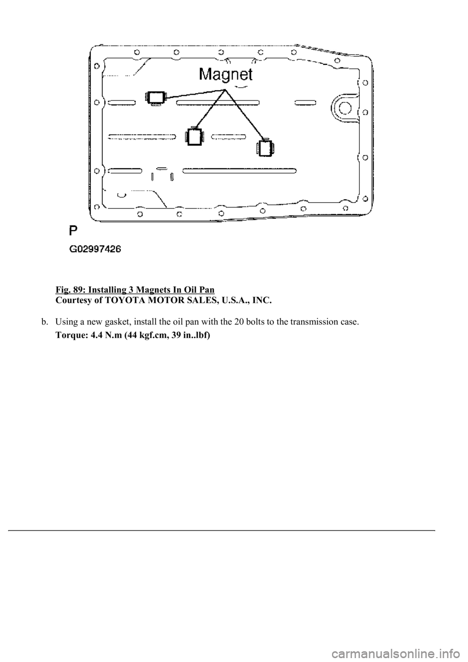
Fig. 89: Installing 3 Magnets In Oil Pan
Courtesy of TOYOTA MOTOR SALES, U.S.A., INC.
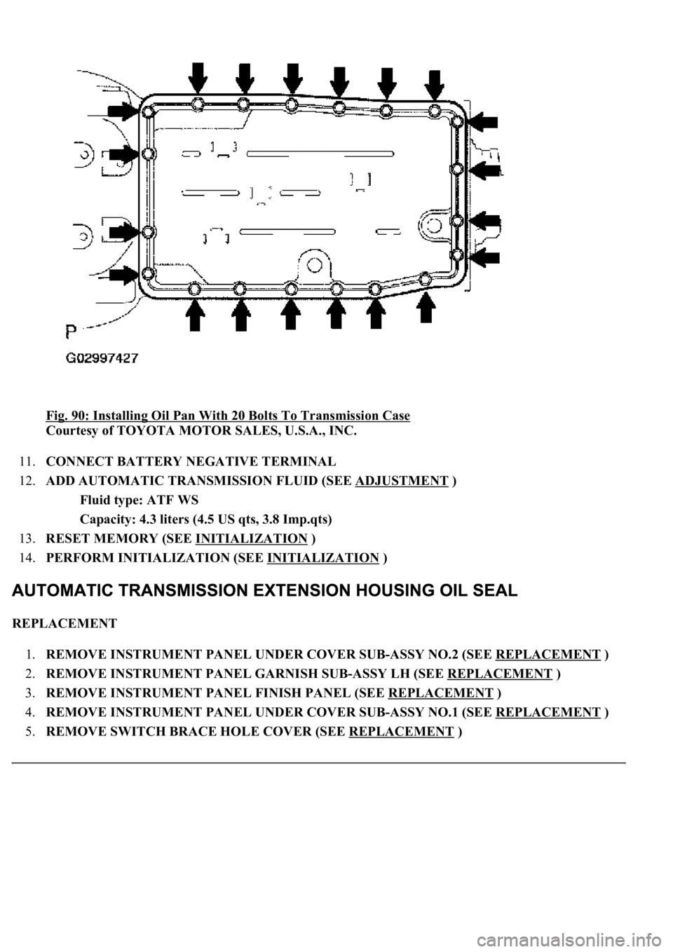
b. Using a new gasket, install the oil pan with the 20 bolts to the transmission case.
Torque: 4.4 N.m (44 kgf.cm, 39 in..lbf)
Page 912 of 4500
Fig. 90: Installing Oil Pan With 20 Bolts To Transmission Case
Courtesy of TOYOTA MOTOR SALES, U.S.A., INC.
11.CONNECT BATTERY NEGATIVE TERMINAL
12.ADD AUTOMATIC TRANSMISSION FLUID (SEE ADJUSTMENT
)
Fluid type: ATF WS
Capacity: 4.3 liters (4.5 US qts, 3.8 Imp.qts)
13.RESET MEMORY (SEE INITIALIZATION
)
14.PERFORM INITIALIZATION (SEE INITIALIZATION
)
REPLACEMENT
1.REMOVE INSTRUMENT PANEL UNDER COVER SUB-ASSY NO.2 (SEE REPLACEMENT
)
2.REMOVE INSTRUMENT PANEL GARNISH SUB-ASSY LH (SEE REPLACEMENT
)
3.REMOVE INSTRUMENT PANEL FINISH PANEL (SEE REPLACEMENT
)
4.REMOVE INSTRUMENT PANEL UNDER COVER SUB-ASSY NO.1 (SEE REPLACEMENT
)
5.REMOVE SWITCH BRACE HOLE COVER (SEE REPLACEMENT
)
Page 913 of 4500
6.REMOVE INSTRUMENT PANEL SAFETY PAD SUB-ASSY NO.1 (SEE REPLACEMENT )
7.REMOVE INSTRUMENT PANEL CUP HOLDER ASSY (SEE REPLACEMENT
)
8.REMOVE CONSOLE UPPER REAR PANEL SUB-ASSY (SEE REPLACEMENT
)
9.REMOVE CONSOLE BOX CARPET (SEE REPLACEMENT
)
10.REMOVE REAR CONSOLE ARMREST ASSY (SEE REPLACEMENT
)
11.REMOVE INSTRUMENT PANEL FINISH PANEL LOWER CENTER (SEE REPLACEMENT
)
12.REMOVE INSTRUMENT CLUSTER FINISH PANEL SUB-ASSY CENTER (SEE
REPLACEMENT
)
13.REMOVE CONSOLE PANEL SUB-ASSY UPPER (SEE REPLACEMENT
)
14.REMOVE CONSOLE BOX (SEE REPLACEMENT
)
15.SEPARATE OXYGEN SENSOR (SEE REPLACEMENT
)
16.REMOVE EXHAUST PIPE ASSY (SEE REPLACEMENT
)
17.REMOVE PROPELLER W/CENTER BEARING SHAFT ASSY (SEE OVERHAUL
)
18.DRAIN AUTOMATIC TRANSMISSION FLUID
a. Remove the drain plug, gasket and drain the ATF.
b. Install a new gasket and the drain plug.
Torque: 20 N.m (205 kgf.cm, 15 ft.lbf)
19.REMOVE AUTOMATIC TRANSMISSION FLANGE YOKE ASSY
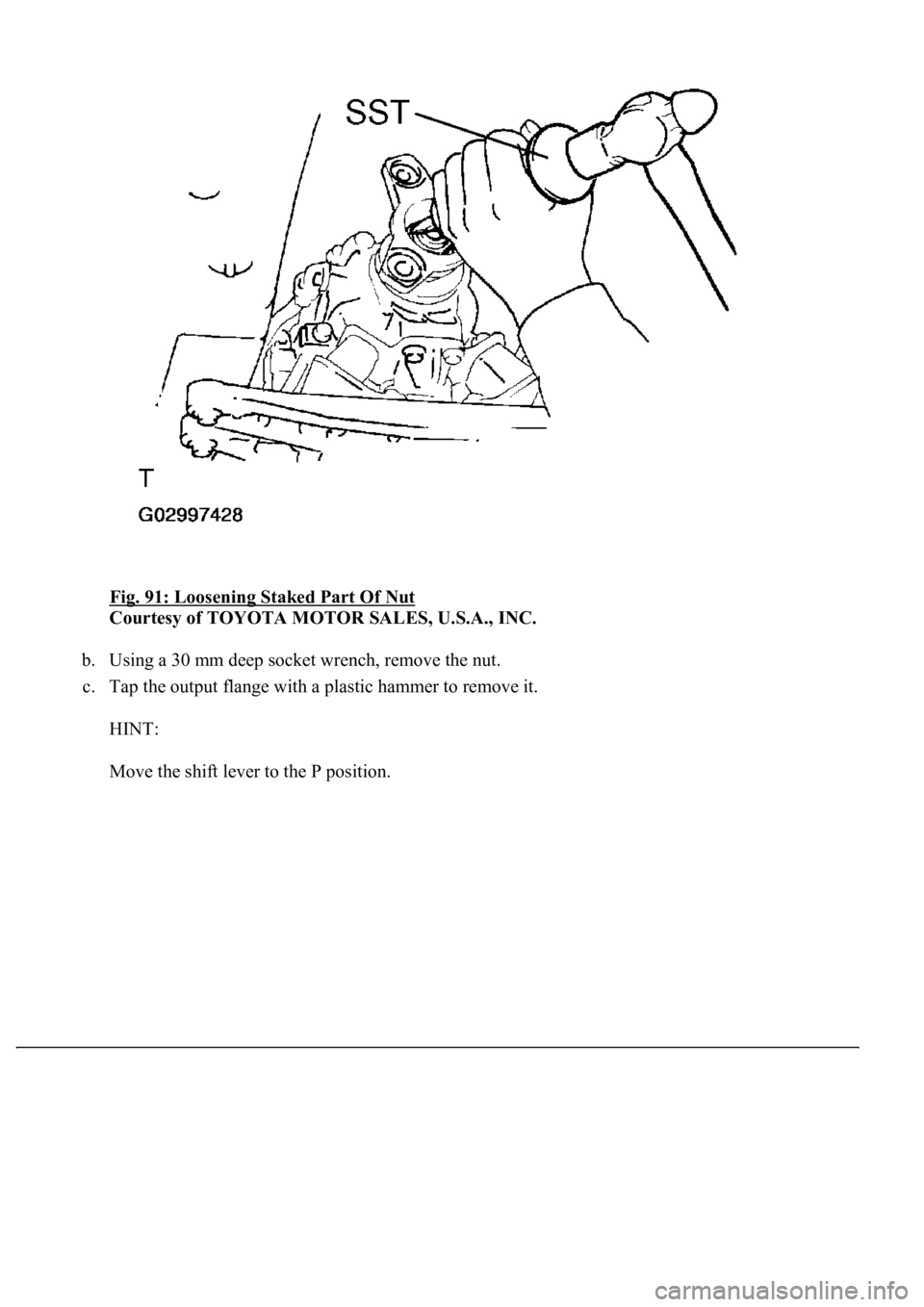
a. Using SST and a hammer, loosen the staked part of the nut.
SST 09930-00010
HINT:
Move the shift lever to the P position.
Page 914 of 4500
Fig. 91: Loosening Staked Part Of Nut
Courtesy of TOYOTA MOTOR SALES, U.S.A., INC.
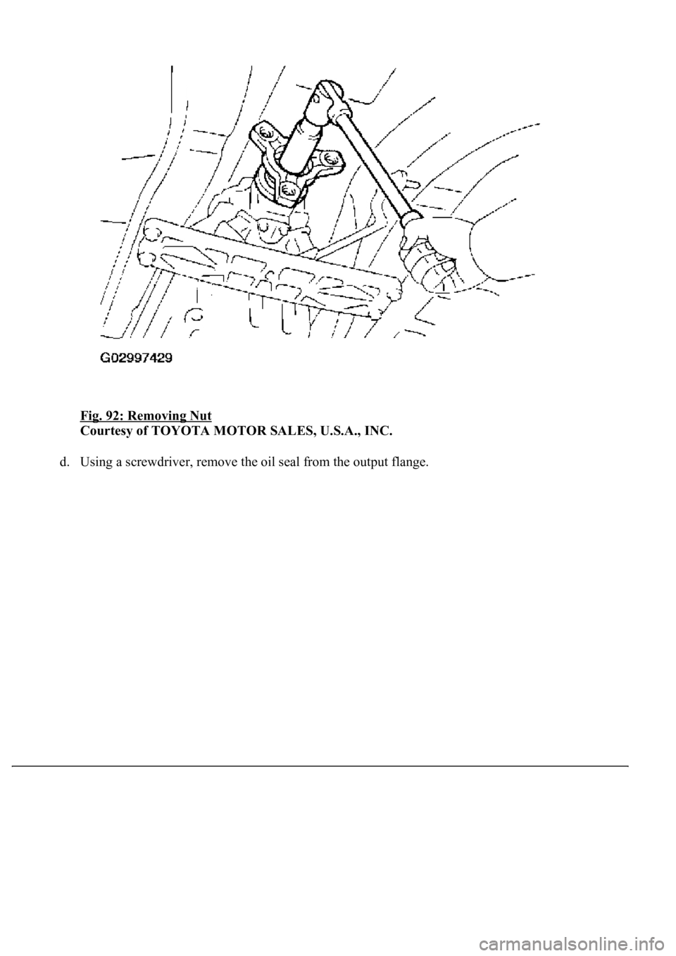
b. Using a 30 mm deep socket wrench, remove the nut.
c. Tap the output flange with a plastic hammer to remove it.
HINT:
Move the shift lever to the P position.
Page 915 of 4500
Fig. 92: Removing Nut
Courtesy of TOYOTA MOTOR SALES, U.S.A., INC.
d. Usin
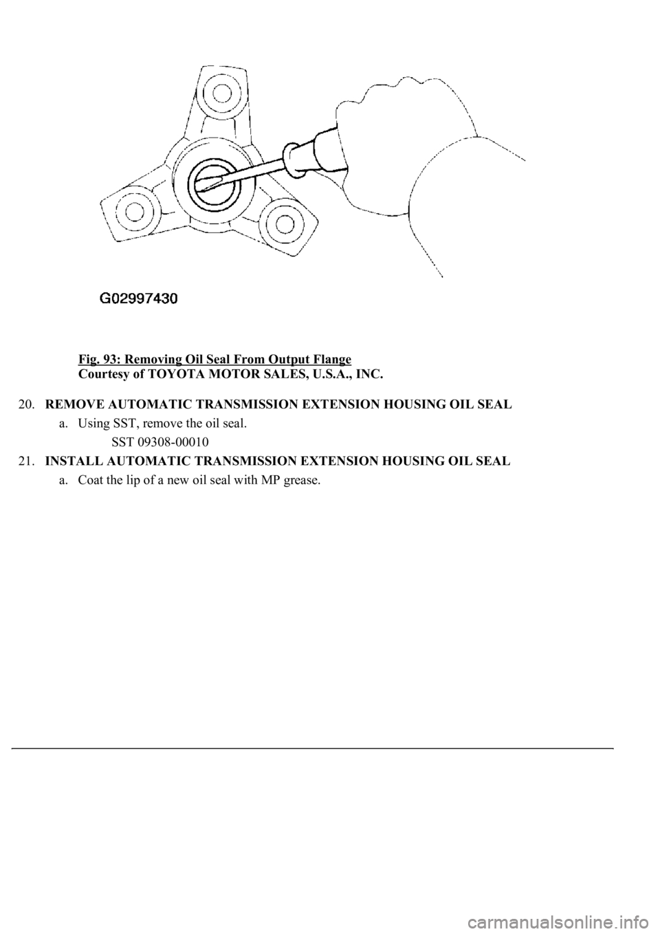
g a screwdriver, remove the oil seal from the output flange.
Page 916 of 4500
Fig. 93: Removing Oil Seal From Output Flange
Courtesy of TOYOTA MOTOR SALES, U.S.A., INC.
20.REMOVE AUTOMATIC TRANSMISSION EXTENSION HOUSING OIL SEAL
a. Using SST, remove the oil seal.
SST 09308-00010
21.INSTALL AUTOMATIC TRANSMISSION EXTENSION HOUSING OIL SEAL
a. Coat the lip of a new oil seal with MP
grease.
Page 917 of 4500
Fig. 94: Removing Oil Seal
Courtesy of TOYOTA MOTOR SALES, U.S.A., INC.
b. Using SST and a hammer, drive in the oil seal with the lip facing downward.
SST 09309-37010
Oil seal depth from flat end: 2.0 mm (0.079 in.)
Page 918 of 4500
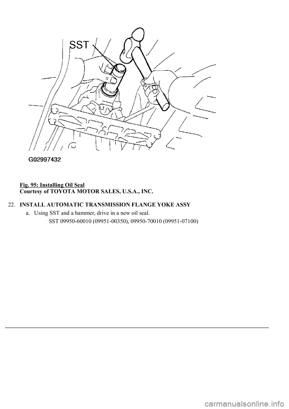
Fig. 95: Installing Oil Seal
Courtesy of TOYOTA MOTOR SALES, U.S.A., INC.
22.INSTALL AUTOMATIC TRANSMISSION FLANGE YOKE ASSY
a. Using SST and a hammer, drive in a new oil seal.
<00360036003700030013001c001c001800130010001900130013001400130003000b0013001c001c00180014001000130013001600180013000c000f00030013001c001c001800130010001a00130013001400130003000b0013001c001c00180014001000
13001a001400130013000c00030003[
Page 919 of 4500
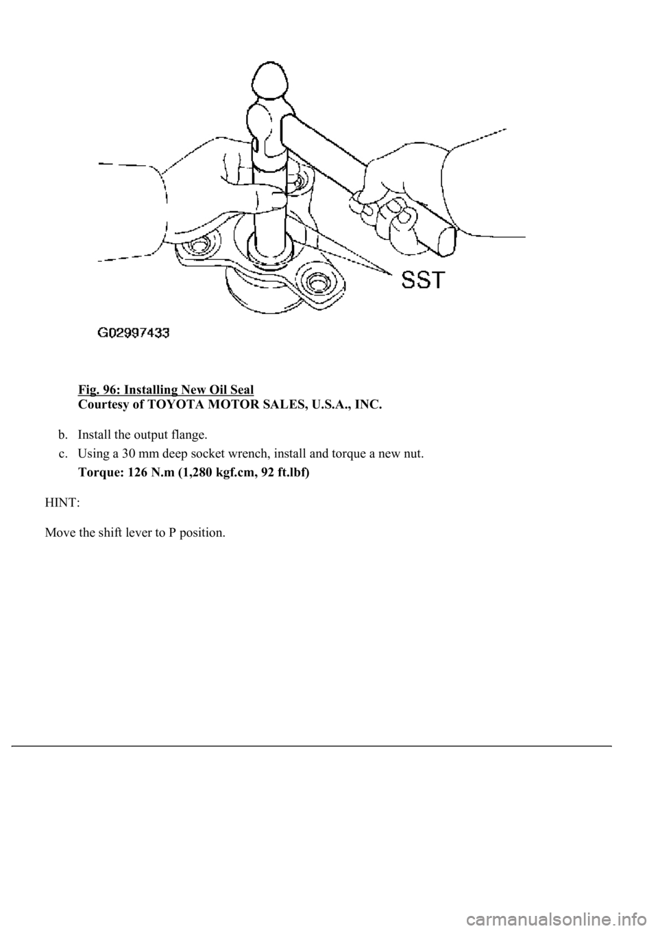
Fig. 96: Installing New Oil Seal
Courtesy of TOYOTA MOTOR SALES, U.S.A., INC.
b. Install the output flange.
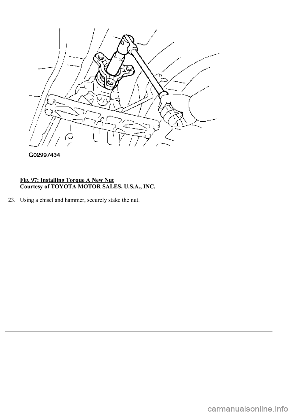
c. Using a 30 mm deep socket wrench, install and torque a new nut.
Torque: 126 N.m (1,280 kgf.cm, 92 ft.lbf)
HINT:
Move the shift lever to P position.
Page 920 of 4500
Fig. 97: Installing Torque A New Nut
Courtesy of TOYOTA MOTOR SALES, U.S.A., INC.
23. Usin
g a chisel and hammer, securely stake the nut.
Trending: Identifying compressor condition, Absorber suspension, Sp2, service reset, USB, evaporator removal, Expansion Valve
