LEXUS LS430 2003 Factory Repair Manual
Manufacturer: LEXUS, Model Year: 2003,
Model line: LS430,
Model: LEXUS LS430 2003
Pages: 4500, PDF Size: 87.45 MB
LEXUS LS430 2003 Factory Repair Manual
LS430 2003
LEXUS
LEXUS
https://www.carmanualsonline.info/img/36/57050/w960_57050-0.png
LEXUS LS430 2003 Factory Repair Manual
Trending: gas type, Max cool damper sensor, vacuum switching valve, heater, check transmission fluid, roof rack, odometer
Page 921 of 4500
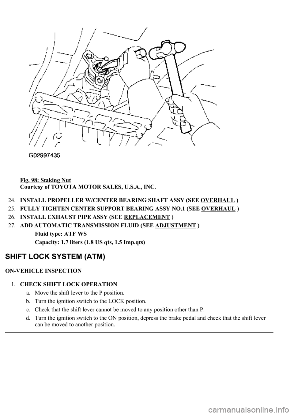
Fig. 98: Staking Nut
Courtesy of TOYOTA MOTOR SALES, U.S.A., INC.
24.INSTALL PROPELLER W/CENTER BEARING SHAFT ASSY (SEE OVERHAUL
)
25.FULLY TIGHTEN CENTER SUPPORT BEARING ASSY NO.1 (SEE OVERHAUL
)
26.INSTALL EXHAUST PIPE ASSY (SEE REPLACEMENT
)
27.ADD AUTOMATIC TRANSMISSION FLUID (SEE ADJUSTMENT
)
Fluid type: ATF WS
Capacity: 1.7 liters (1.8 US qts, 1.5 Imp.qts)
ON-VEHICLE INSPECTION
1.CHECK SHIFT LOCK OPERATION
a. Move the shift lever to the P position.
b. Turn the ignition switch to the LOCK position.
c. Check that the shift lever cannot be moved to any position other than P.
d. Turn the ignition switch to the ON position, depress the brake pedal and check that the shift lever
can be moved to another position.
Page 922 of 4500
If the operation cannot be done as specified, inspect the shift lock control unit.
2.CHECK SHIFT LOCK RELEASE BUTTON OPERATION
a. Using a small screwdriver, remove the shift lock release cover.
b. When operating the shift lever with the shift lock release button pressed, check that the lever can be
moved to any position other than P.
If the operation cannot be done as specified, check the shift lever assy installation condition.
3.CHECK KEY INTERLOCK OPERATION
a. Turn the ignition switch to the ON position.
b. Depress the brake pedal and adjust the shift lever to any position other than P.
c. Check that the ignition key cannot be turned to the LOCK position.
d. Move the shift lever to the P position, turn the ignition key to the LOCK position and check that the
ignition key can be removed.
If the operation cannot be done as specified, inspect the shift lock control unit.
4.INSPECT SHIFT LOCK CONTROL UNIT ASSEMBLY
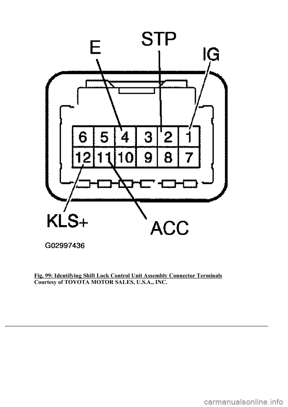
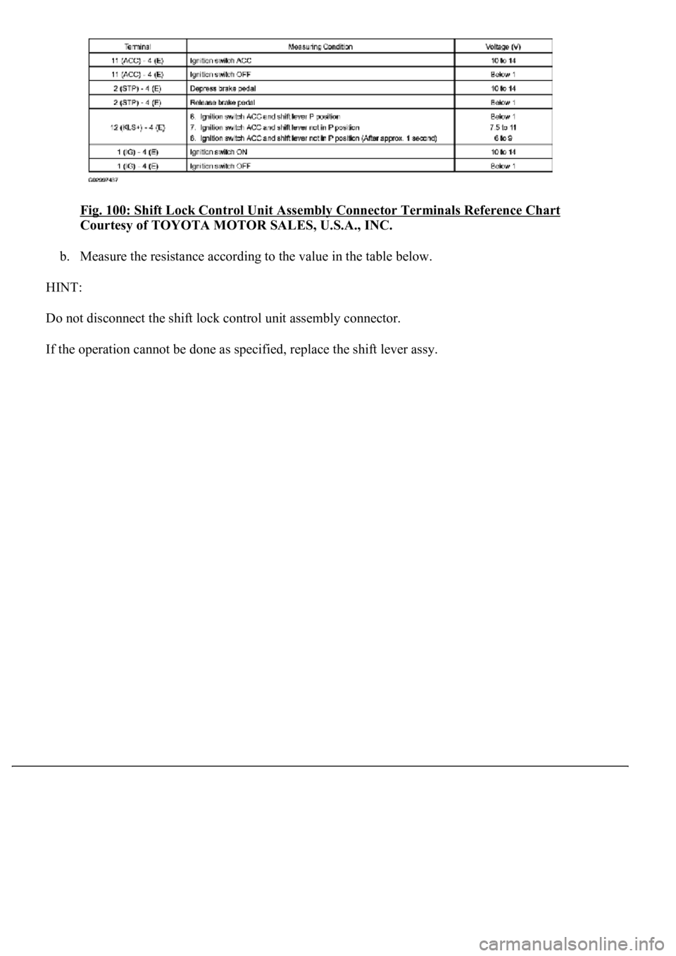
a. Measure the voltage according to the value(s) in the table below.
HINT:
Do not disconnect the shift lock control unit assembl
y connector.
Page 923 of 4500
Fig. 99: Identifying Shift Lock Control Unit Assembly Connector Terminals
Courtesy of TOYOTA MOTOR SALES, U.S.A., INC.
Page 924 of 4500
Fig. 100: Shift Lock Control Unit Assembly Connector Terminals Reference Chart
Courtesy of TOYOTA MOTOR SALES, U.S.A., INC.
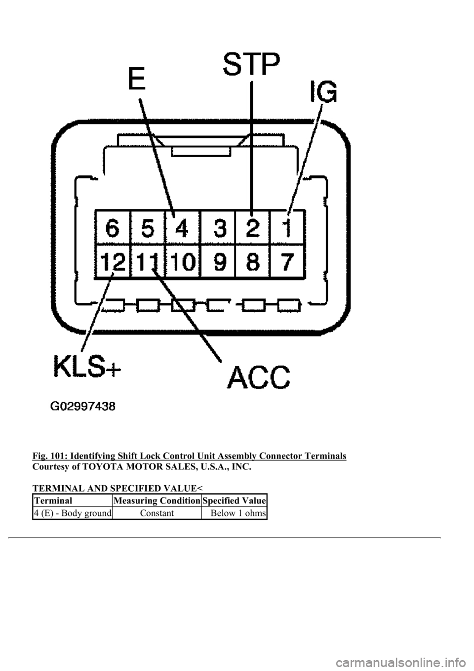
b. Measure the resistance according to the value in the table below.
HINT:
Do not disconnect the shift lock control unit assembly connector.
If the operation cannot be done as specified, replace the shift lever ass
y.
Page 925 of 4500
Fig. 101: Identifying Shift Lock Control Unit Assembly Connector Terminals
Courtesy of TOYOTA MOTOR SALES, U.S.A., INC.
TERMINAL AND SPECIFIED VALUE<
TerminalMeasuring ConditionSpecified Value
4 (E) - Body groundConstantBelow 1 ohms
Page 926 of 4500
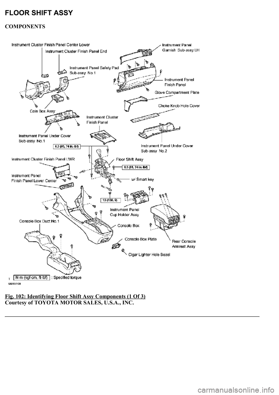
COMPONENTS
Fig. 102: Identifying Floor Shift Assy Components (1 Of 3)
Courtesy of TOYOTA MOTOR SALES, U.S.A., INC.
Page 927 of 4500
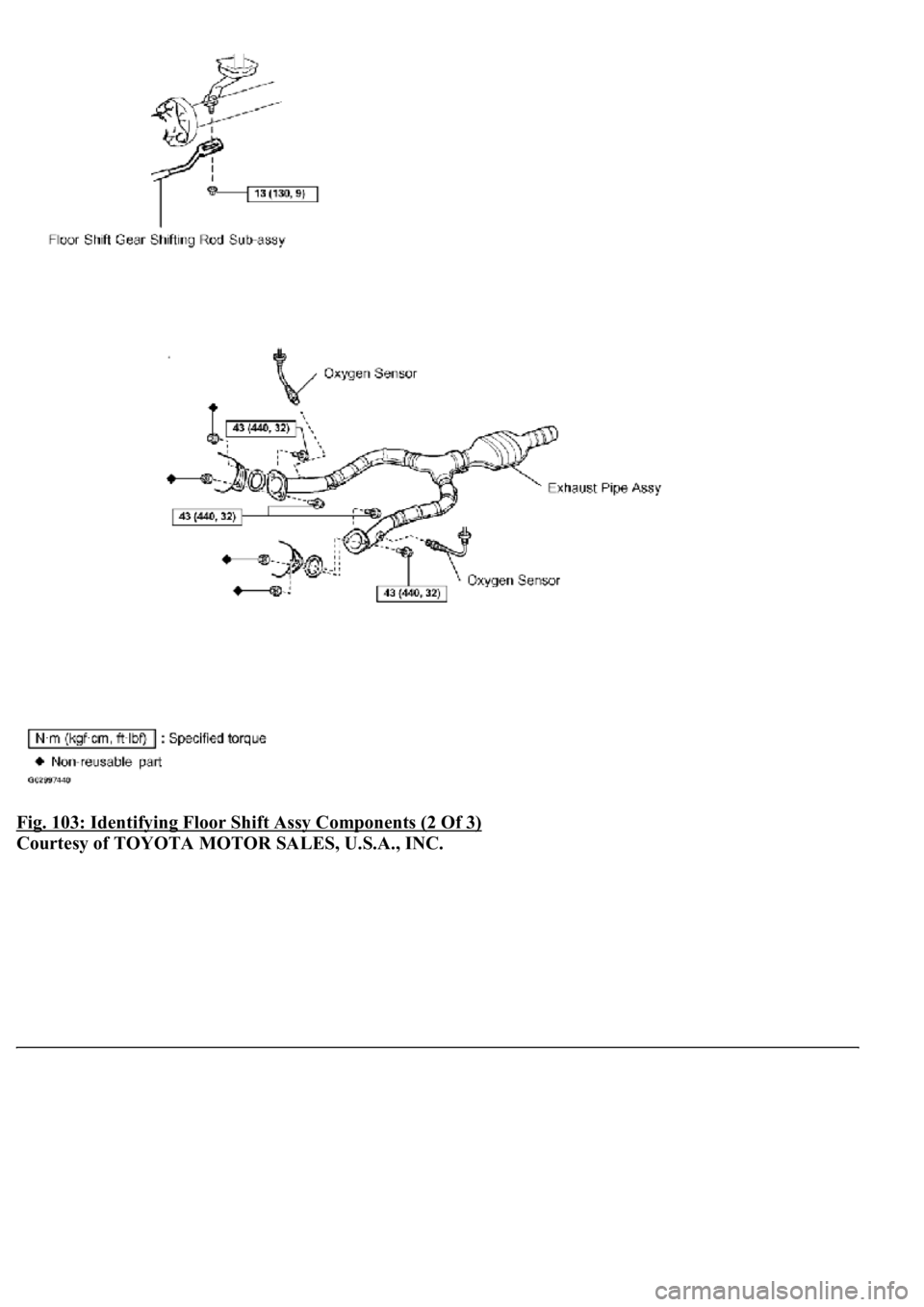
Fig. 103: Identifying Floor Shift Assy Components (2 Of 3)
Courtesy of TOYOTA MOTOR SALES, U.S.A., INC.
Page 928 of 4500
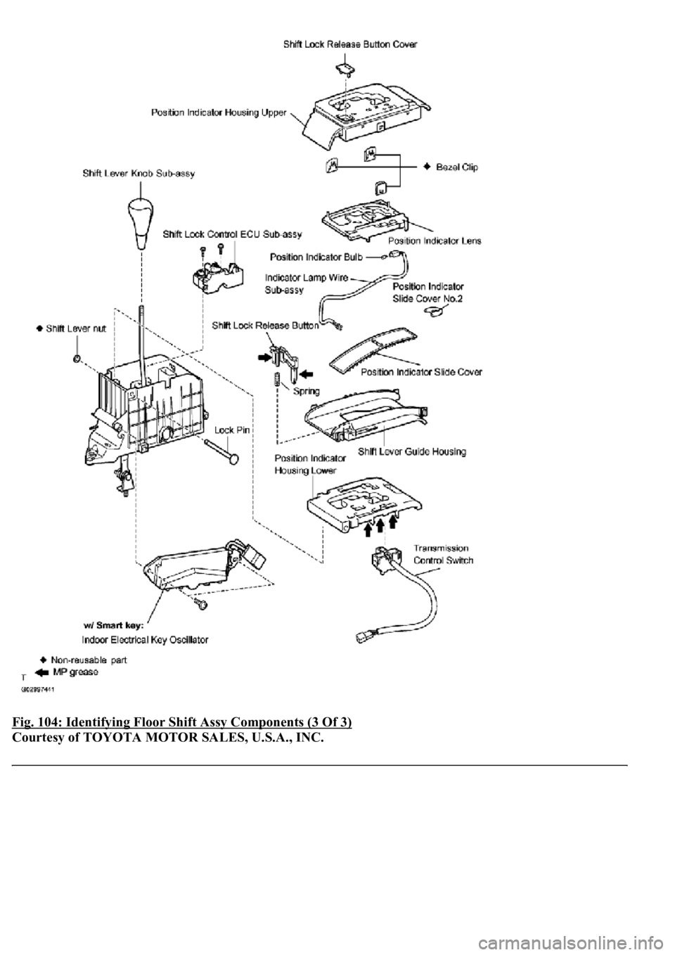
Fig. 104: Identifying Floor Shift Assy Components (3 Of 3)
Courtesy of TOYOTA MOTOR SALES, U.S.A., INC.
Page 929 of 4500
OVERHAUL
1.DISCONNECT BATTERY NEGATIVE TERMINAL
2.REMOVE INSTRUMENT PANEL UNDER COVER SUB-ASSY NO.2 (SEE REPLACEMENT
)
3.REMOVE CHOKE KNOB HOLE COVER (SEE REPLACEMENT
)
4.REMOVE GLOVE COMPARTMENT PLATE (SEE REPLACEMENT
)
5.REMOVE INSTRUMENT PANEL GARNISH SUB-ASSY LH (SEE REPLACEMENT
)
6.REMOVE INSTRUMENT PANEL FINISH PANEL (SEE REPLACEMENT
)
7.REMOVE INSTRUMENT CLUSTER FINISH PANEL (SEE REPLACEMENT
)
8.REMOVE INSTRUMENT PANEL FINISH PANEL LOWER CENTER (SEE REPLACEMENT
)
9.REMOVE PANEL INSTRUMENT CLUSTER FINISH LOWER (SEE REPLACEMENT
)
10.REMOVE INSTRUMENT PANEL UNDER COVER SUB-ASSY NO.1 (SEE REPLACEMENT
)
11.REMOVE COIN BOX ASSY (SEE REPLACEMENT
)
12.REMOVE INSTRUMENT CLUSTER FINISH PANEL CENTER LOWER (SEE
REPLACEMENT
)
13.REMOVE CIGAR LIGHTER HOLE BEZEL (SEE REPLACEMENT
)
14.REMOVE INSTRUMENTAL CLUSTER FINISH PANEL END (SEE REPLACEMENT
)
15.REMOVE INSTRUMENT PANEL SAFETY PAD SUB-ASSY NO.1 (SEE REPLACEMENT
)
16.REMOVE REAR CONSOLE ARMREST ASSY (SEE REPLACEMENT
)
17.REMOVE CONSOLE BOX PLATE (SEE REPLACEMENT
)
18.REMOVE INSTRUMENT PANEL CUP HOLDER ASSY (SEE REPLACEMENT
)
19.REMOVE CONSOLE BOX (SEE REPLACEMENT
)
20.REMOVE CONSOLE BOX DUCT NO.1 (SEE REPLACEMENT
)
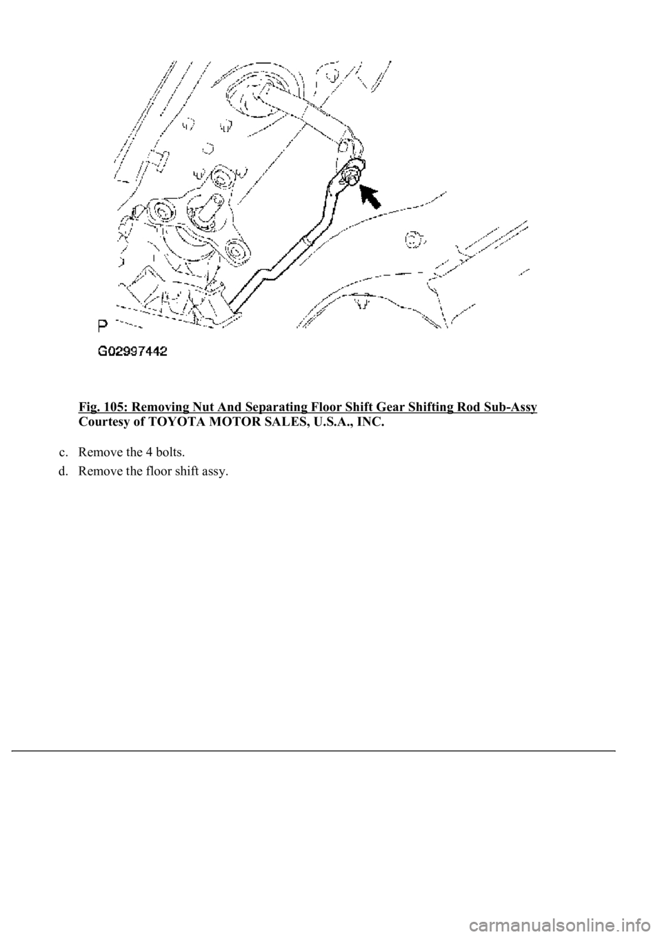
21.SEPARATE FLOOR SHIFT GEAR SHIFTING ROD SUB-ASSY
a. Remove the nut and separate the floor shift gear shifting rod sub-assy.
22.REMOVE FLOOR SHIFT ASSY
a. Disconnect the connector.
b. Disconnect the indoor electrical key oscillator connector. (w/smart key)
Page 930 of 4500
Fig. 105: Removing Nut And Separating Floor Shift Gear Shifting Rod Sub-Assy
Courtesy of TOYOTA MOTOR SALES, U.S.A., INC.
c. Remove the 4 bolts.
d. Remove the floor shift ass
y.
Trending: height, oil filter, fuses, maintenance reset, instrument cluster, cooling, STARTER
