LEXUS LS430 2003 Factory Repair Manual
Manufacturer: LEXUS, Model Year: 2003,
Model line: LS430,
Model: LEXUS LS430 2003
Pages: 4500, PDF Size: 87.45 MB
LEXUS LS430 2003 Factory Repair Manual
LS430 2003
LEXUS
LEXUS
https://www.carmanualsonline.info/img/36/57050/w960_57050-0.png
LEXUS LS430 2003 Factory Repair Manual
Trending: Rear, Identifying condition, content, Lock actuator, battery, lock, drain bolt
Page 871 of 4500
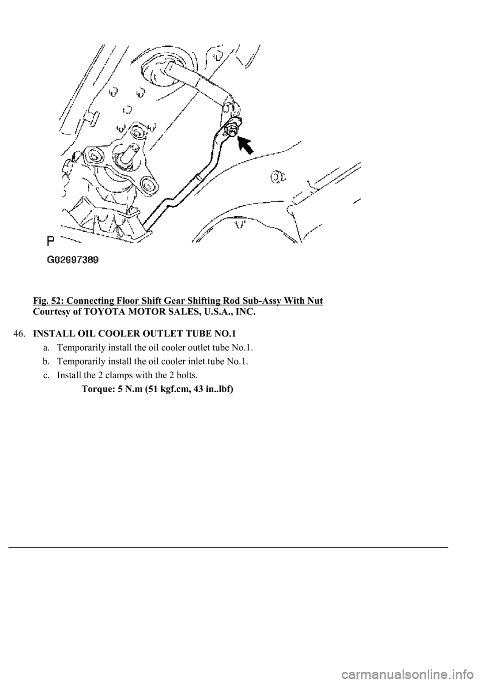
<0029004c004a0011000300180015001d00030026005200510051004800460057004c0051004a00030029004f00520052005500030036004b004c004900570003002a00480044005500030036004b004c00490057004c0051004a0003003500520047000300
3600580045[-Assy With Nut
Courtesy of TOYOTA MOTOR SALES, U.S.A., INC.
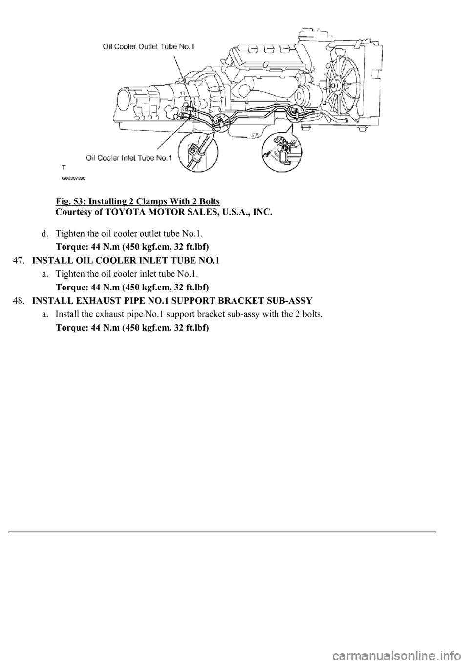
46.INSTALL OIL COOLER OUTLET TUBE NO.1
a. Temporarily install the oil cooler outlet tube No.1.
b. Temporarily install the oil cooler inlet tube No.1.
c. Install the 2 clamps with the 2 bolts.
Torque: 5 N.m (51 kgf.cm, 43 in..lbf)
Page 872 of 4500
Fig. 53: Installing 2 Clamps With 2 Bolts
Courtesy of TOYOTA MOTOR SALES, U.S.A., INC.
d. Tighten the oil cooler outlet tube No.1.
Torque: 44 N.m (450 kgf.cm, 32 ft.lbf)
47.INSTALL OIL COOLER INLET TUBE NO.1
a. Tighten the oil cooler inlet tube No.1.
Torque: 44 N.m (450 kgf.cm, 32 ft.lbf)
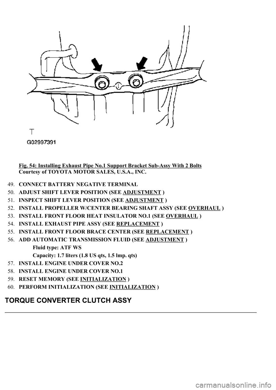
48.INSTALL EXHAUST PIPE NO.1 SUPPORT BRACKET SUB-ASSY
a. Install the exhaust pipe No.1 support bracket sub-assy with the 2 bolts.
Torque: 44 N.m (450 kgf.cm, 32 ft.lbf)
Page 873 of 4500
Fig. 54: Installing Exhaust Pipe No.1 Support Bracket Sub-Assy With 2 Bolts
Courtesy of TOYOTA MOTOR SALES, U.S.A., INC.
49.CONNECT BATTERY NEGATIVE TERMINAL
50.ADJUST SHIFT LEVER POSITION (SEE ADJUSTMENT
)
51.INSPECT SHIFT LEVER POSITION (SEE ADJUSTMENT
)
52.INSTALL PROPELLER W/CENTER BEARING SHAFT ASSY (SEE OVERHAUL
)
53.INSTALL FRONT FLOOR HEAT INSULATOR NO.1 (SEE OVERHAUL
)
54.INSTALL EXHAUST PIPE ASSY (SEE REPLACEMENT
)
55.INSTALL FRONT FLOOR BRACE CENTER (SEE REPLACEMENT
)
56.ADD AUTOMATIC TRANSMISSION FLUID (SEE ADJUSTMENT
)
Fluid type: ATF WS
Capacity: 1.7 liters (1.8 US qts, 1.5 lmp. qts)
57.INSTALL ENGINE UNDER COVER NO.2
58.INSTALL ENGINE UNDER COVER NO.1
59.RESET MEMORY (SEE INITIALIZATION
)
60.PERFORM INITIALIZATION (SEE INITIALIZATION
)
Page 874 of 4500
INSPECTION
1.INSPECT TORQUE CONVERTER CLUTCH ASSY
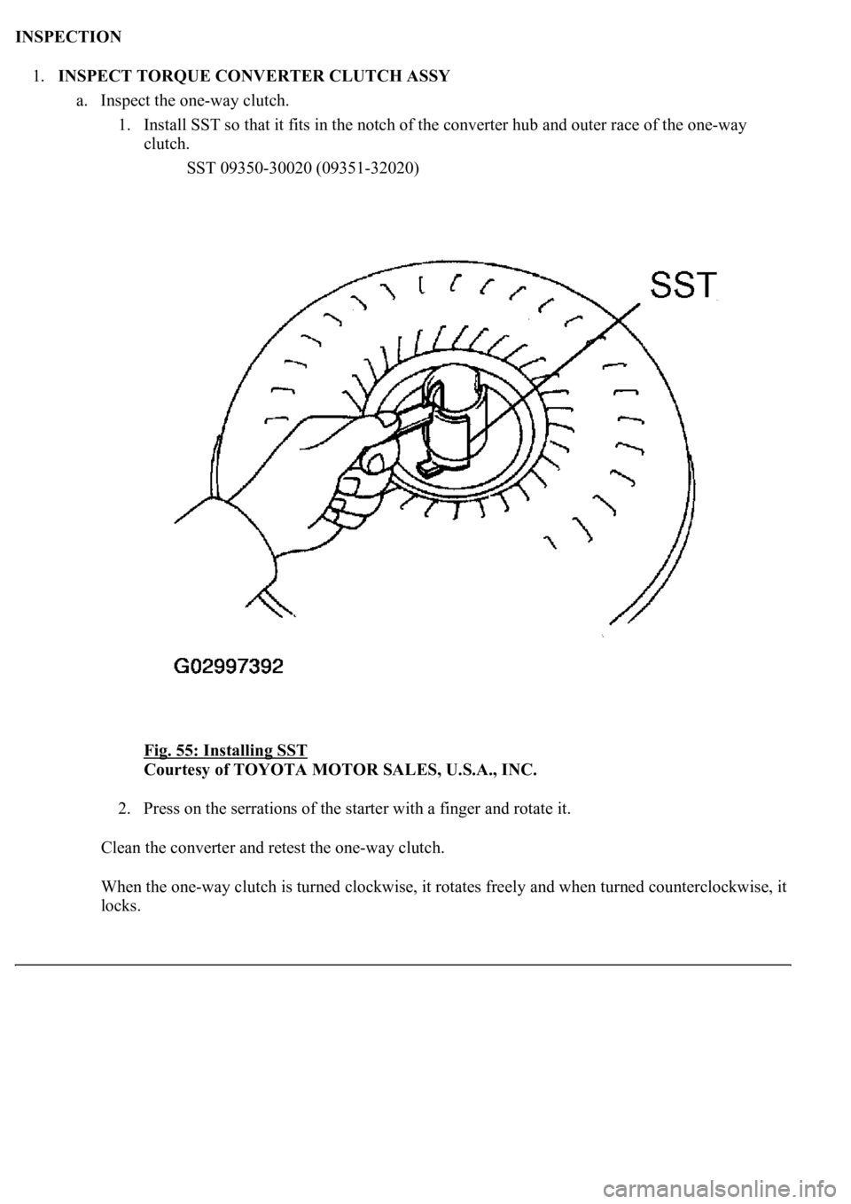
a. Inspect the one-way clutch.
1. Install SST so that it fits in the notch of the converter hub and outer race of the one-way
clutch.
SST 09350-30020 (09351-32020)
Fig. 55: Installing SST
Courtesy of TOYOTA MOTOR SALES, U.S.A., INC.
2. Press on the serrations of the starter with a finger and rotate it.
Clean the converter and retest the one-way clutch.
When the one-way clutch is turned clockwise, it rotates freely and when turned counterclockwise, it
locks.
Page 875 of 4500
Fig. 56: Pressing On Serrations Of Starter
Courtesy of TOYOTA MOTOR SALES, U.S.A., INC.
b. Determine the condition of the torque converter clutch assy.
1. If the inspection result of the torque converter clutch assy does not satisfy the standard
conditions, replace the torque converter clutch assy.
Malfunction item:
A metallic sound is emitted from the torque converter clutch assy during the stall test
<005200550003005a004b0048005100030057004b004800030056004b004c004900570003004f00480059004800550003004c005600030050005200590048004700030057005200030057004b0048000300310003005300520056004c0057004c0052005100
11[
The one-way clutch is free or locked in both directions.
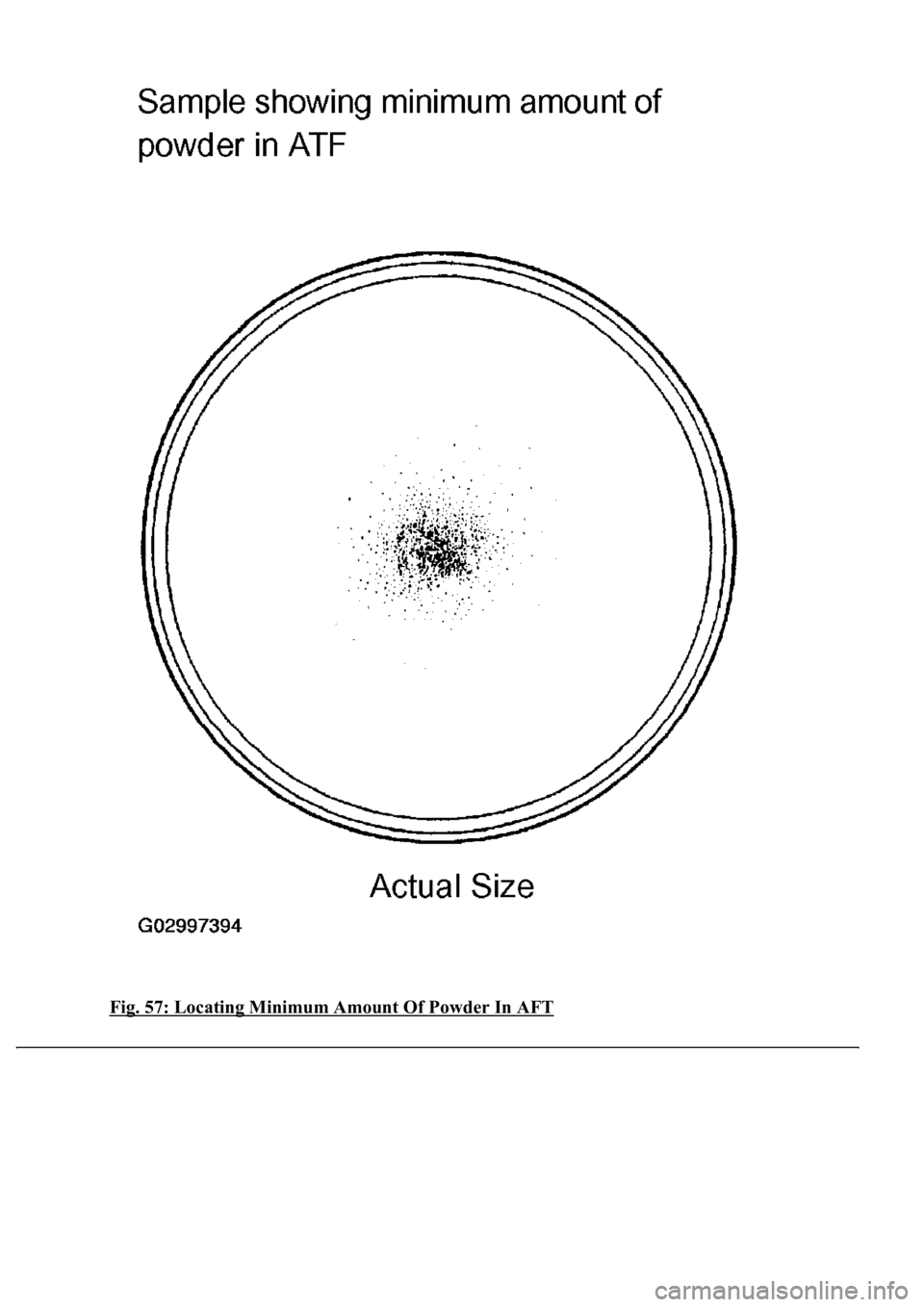
The amount of powder in the ATF is greater than the sample shown on the illust (see
the sample).
HINT:
The sample shows the auto fluid of approximately 0.25 liters (0.26 US qts, 0.22 Imp. qts) that is
<00570044004e0048005100030052005800570003004900550052005000030057004b0048000300550048005000520059004800470003005700520055005400580048000300460052005100590048005500570048005500030046004f005800570046004b00
11[
Page 876 of 4500
c. Change the ATF in the torque converter clutch.
1. If the ATF is discolored and/or has a foul odor, completely stir the ATF in the torque
converter clutch and drain the ATF with the torque converter facin
g up.
Page 877 of 4500
Fig. 57: Locating Minimum Amount Of Powder In AFT
Page 878 of 4500
Courtesy of TOYOTA MOTOR SALES, U.S.A., INC.
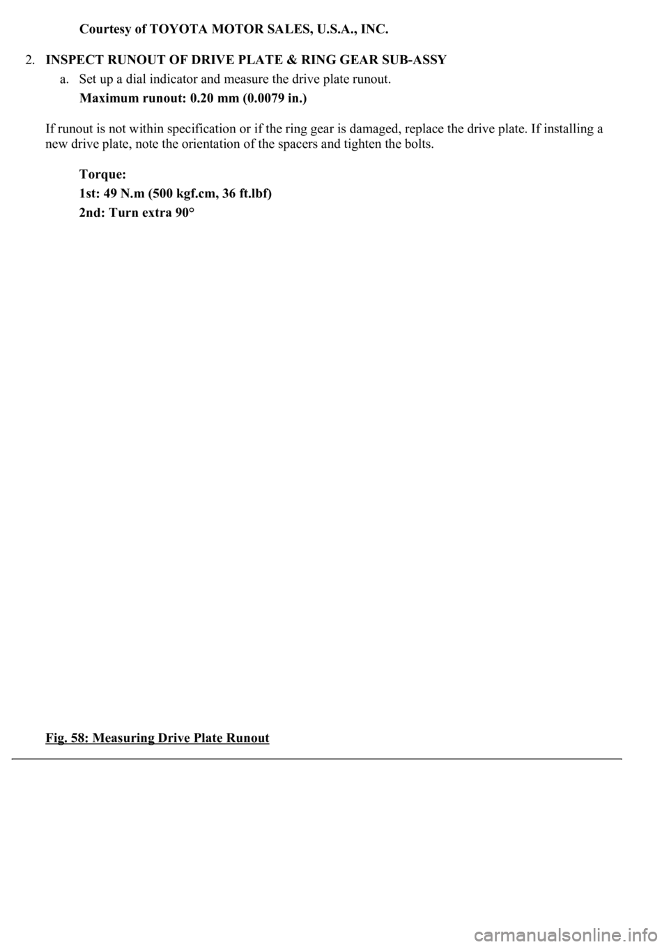
2.INSPECT RUNOUT OF DRIVE PLATE & RING GEAR SUB-ASSY
a. Set up a dial indicator and measure the drive plate runout.
Maximum runout: 0.20 mm (0.0079 in.)
If runout is not within specification or if the ring gear is damaged, replace the drive plate. If installing a
new drive plate, note the orientation of the spacers and tighten the bolts.
Torque:
1st: 49 N.m (500 kgf.cm, 36 ft.lbf)
2nd: Turn extra 90°
Fig. 58: Measuring Drive Plate Runout
Page 879 of 4500
Courtesy of TOYOTA MOTOR SALES, U.S.A., INC.
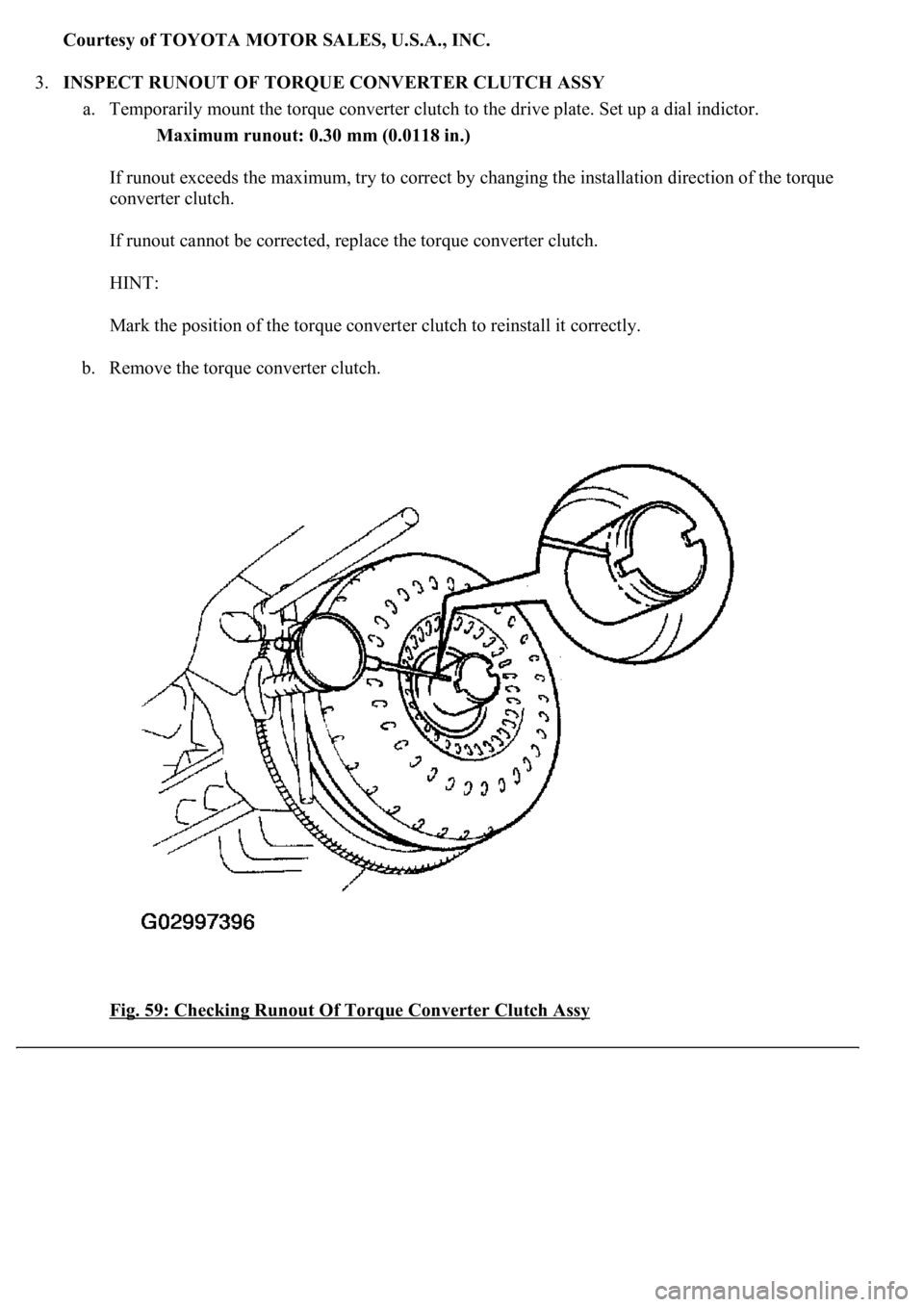
3.INSPECT RUNOUT OF TORQUE CONVERTER CLUTCH ASSY
a. Temporarily mount the torque converter clutch to the drive plate. Set up a dial indictor.
Maximum runout: 0.30 mm (0.0118 in.)
If runout exceeds the maximum, try to correct by changing the installation direction of the torque
converter clutch.
If runout cannot be corrected, replace the torque converter clutch.
HINT:
Mark the position of the torque converter clutch to reinstall it correctly.
b. Remove the torque converter clutch.
Fig. 59: Checking Runout Of Torque Converter Clutch Assy
Page 880 of 4500
Courtesy of TOYOTA MOTOR SALES, U.S.A., INC.
REPLACEMENT
<00380056004c0051004a00030044000300550044005d0052005500030045004f00440047004800030044005100470003004a00440056004e0048005700030056004600550044005300480055000f000300550048005000520059004800030044004f004f00
030057004b004800030052004f004700030029002c0033002a[ material from the gasket surfaces.
Thoroughly clean all components to remove any loose material.
Clean both sealing surfaces with a non-residue solvent.
Apply FIPG in a continuous line width approximately 1 mm (0.04 in.) along the sealing surface.
Parts must be assembled within 10 minutes of application. Otherwise, the FIPG material must be
removed and reapplied.
1.DISCONNECT BATTERY NEGATIVE TERMINAL
2.DRAIN AUTOMATIC TRANSMISSION FLUID
a. Remove the drain plug, gasket and drain the ATF.
b. Install a new gasket and the drain plug.
Torque: 20 N.m (205 kgf.cm, 15 ft.lbf)
3.REMOVE AUTOMATIC TRANSMISSION OIL PAN SUB-ASSY
a. Remove the 20 bolts, oil pan and
gasket.
Trending: fuel consumption, vacuum switch, washer fluid, service interval, gas type, key battery, parking brake
