MAZDA 6 2002 Suplement Owner's Manual
Manufacturer: MAZDA, Model Year: 2002, Model line: 6, Model: MAZDA 6 2002Pages: 909, PDF Size: 17.16 MB
Page 21 of 909

SCHEDULED MAINTENANCE
GI–17
GI
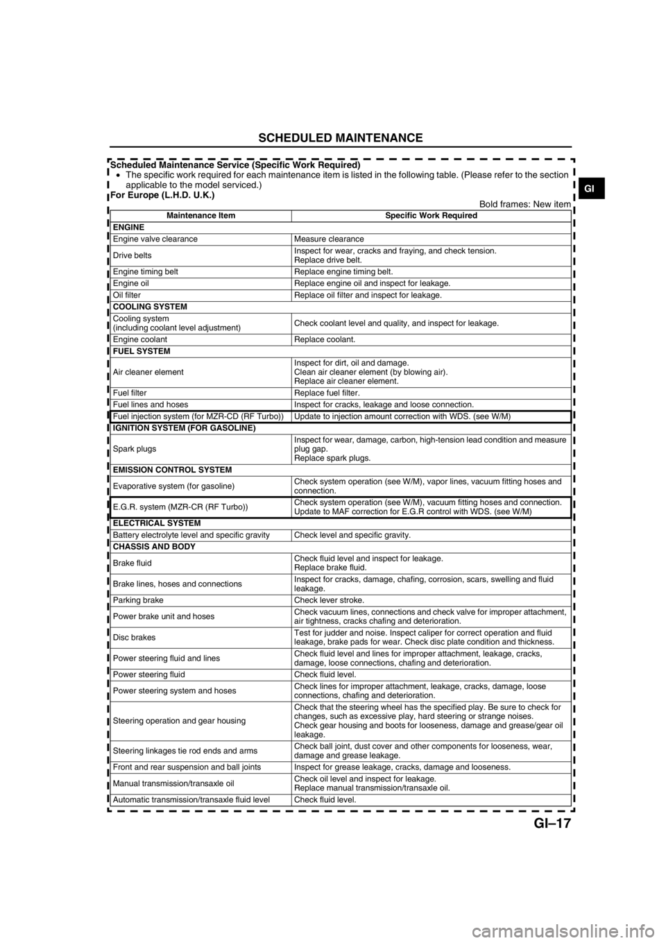
Scheduled Maintenance Service (Specific Work Required)
•The specific work required for each maintenance item is listed in the following table. (Please refer to the section
applicable to the model serviced.)
For Europe (L.H.D. U.K.)
Bold frames: New item
Maintenance Item Specific Work Required
ENGINE
Engine valve clearance Measure clearance
Drive beltsInspect for wear, cracks and fraying, and check tension.
Replace drive belt.
Engine timing belt Replace engine timing belt.
Engine oil Replace engine oil and inspect for leakage.
Oil filter Replace oil filter and inspect for leakage.
COOLING SYSTEM
Cooling system
(including coolant level adjustment)Check coolant level and quality, and inspect for leakage.
Engine coolant Replace coolant.
FUEL SYSTEM
Air cleaner elementInspect for dirt, oil and damage.
Clean air cleaner element (by blowing air).
Replace air cleaner element.
Fuel filter Replace fuel filter.
Fuel lines and hoses Inspect for cracks, leakage and loose connection.
Fuel injection system (for MZR-CD (RF Turbo)) Update to injection amount correction with WDS. (see W/M)
IGNITION SYSTEM (FOR GASOLINE)
Spark plugsInspect for wear, damage, carbon, high-tension lead condition and measure
plug gap.
Replace spark plugs.
EMISSION CONTROL SYSTEM
Evaporative system (for gasoline)Check system operation (see W/M), vapor lines, vacuum fitting hoses and
connection.
E.G.R. system (MZR-CR (RF Turbo))Check system operation (see W/M), vacuum fitting hoses and connection.
Update to MAF correction for E.G.R control with WDS. (see W/M)
ELECTRICAL SYSTEM
Battery electrolyte level and specific gravity Check level and specific gravity.
CHASSIS AND BODY
Brake fluidCheck fluid level and inspect for leakage.
Replace brake fluid.
Brake lines, hoses and connectionsInspect for cracks, damage, chafing, corrosion, scars, swelling and fluid
leakage.
Parking brake Check lever stroke.
Power brake unit and hosesCheck vacuum lines, connections and check valve for improper attachment,
air tightness, cracks chafing and deterioration.
Disc brakesTest for judder and noise. Inspect caliper for correct operation and fluid
leakage, brake pads for wear. Check disc plate condition and thickness.
Power steering fluid and linesCheck fluid level and lines for improper attachment, leakage, cracks,
damage, loose connections, chafing and deterioration.
Power steering fluid Check fluid level.
Power steering system and hosesCheck lines for improper attachment, leakage, cracks, damage, loose
connections, chafing and deterioration.
Steering operation and gear housingCheck that the steering wheel has the specified play. Be sure to check for
changes, such as excessive play, hard steering or strange noises.
Check gear housing and boots for looseness, damage and grease/gear oil
leakage.
Steering linkages tie rod ends and armsCheck ball joint, dust cover and other components for looseness, wear,
damage and grease leakage.
Front and rear suspension and ball joints Inspect for grease leakage, cracks, damage and looseness.
Manual transmission/transaxle oilCheck oil level and inspect for leakage.
Replace manual transmission/transaxle oil.
Automatic transmission/transaxle fluid level Check fluid level.
Page 22 of 909

GI–18
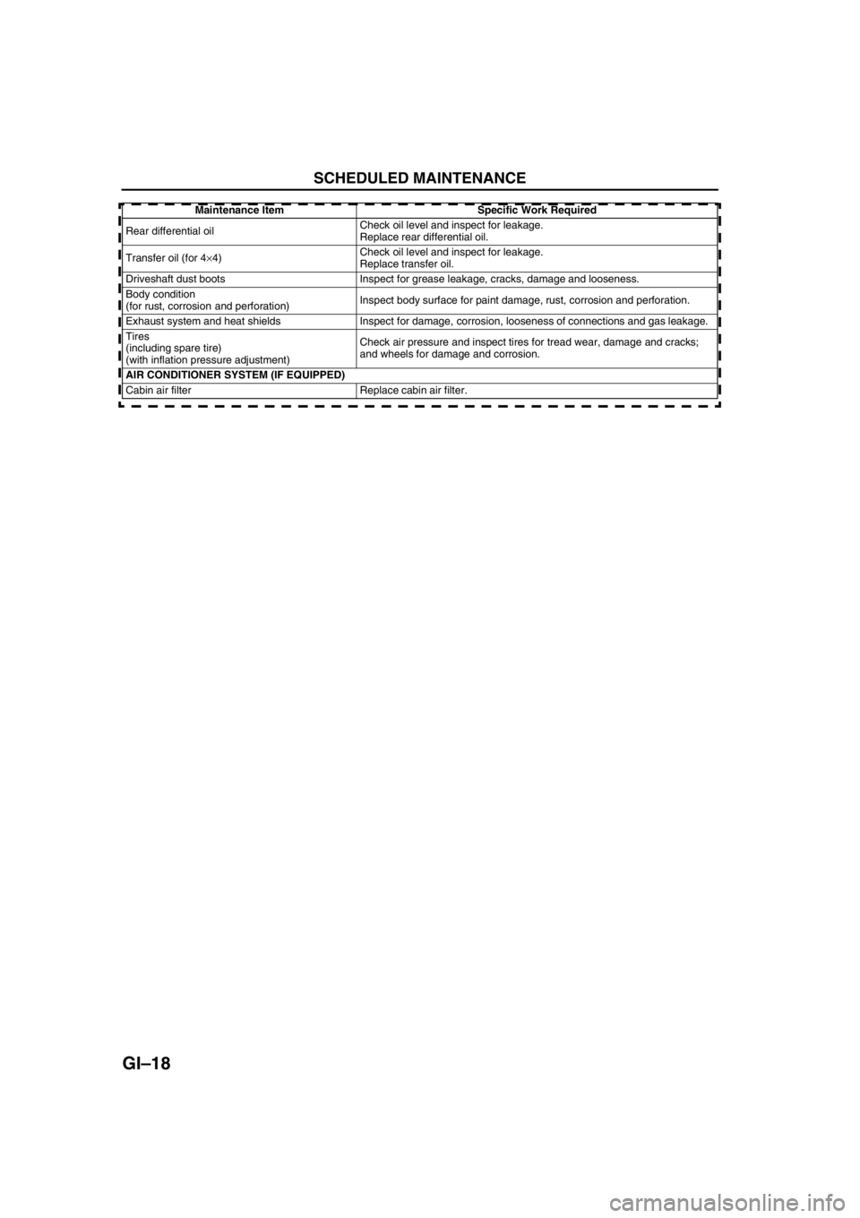
SCHEDULED MAINTENANCE
End Of Sie
Rear differential oilCheck oil level and inspect for leakage.
Replace rear differential oil.
Transfer oil (for 4×4)Check oil level and inspect for leakage.
Replace transfer oil.
Driveshaft dust boots Inspect for grease leakage, cracks, damage and looseness.
Body condition
(for rust, corrosion and perforation)Inspect body surface for paint damage, rust, corrosion and perforation.
Exhaust system and heat shields Inspect for damage, corrosion, looseness of connections and gas leakage.
Tires
(including spare tire)
(with inflation pressure adjustment)Check air pressure and inspect tires for tread wear, damage and cracks;
and wheels for damage and corrosion.
AIR CONDITIONER SYSTEM (IF EQUIPPED)
Cabin air filter Replace cabin air filter.Maintenance Item Specific Work Required
Page 23 of 909
![MAZDA 6 2002 Suplement Owners Manual B1–1
B1
B1ENGINE [L8, LF, L3]
OUTLINE.............................................................. B1-2
OUTLINE OF CONSTRUCTION........................ B1-2
FEATURES ............................... MAZDA 6 2002 Suplement Owners Manual B1–1
B1
B1ENGINE [L8, LF, L3]
OUTLINE.............................................................. B1-2
OUTLINE OF CONSTRUCTION........................ B1-2
FEATURES ...............................](/img/28/57057/w960_57057-22.png)
B1–1
B1
B1ENGINE [L8, LF, L3]
OUTLINE.............................................................. B1-2
OUTLINE OF CONSTRUCTION........................ B1-2
FEATURES ........................................................ B1-2
ENGINE PERFORMANCE CURVE ................... B1-2
SPECIFICATIONS ............................................. B1-3
OUTLINE.............................................................. B1-4
SUPPLEMENTAL SERVICE INFORMATION ... B1-4
ENGINE................................................................ B1-4
ENGINE REMOVAL/INSTALLATION (4WD) ..... B1-4 FEATURES
SERVICE
Page 24 of 909

B1–2
OUTLINE
OUTLINE OF CONSTRUCTIONA6E220202000201•The construction and operation of the new Mazda6 (GG, GY) L8, LF, and L3 engine is the same as that of the
current Mazda6 (GG) L8, LF, and L3 engine models except for the following features. (See Mazda6 training
Manual 3359-1*-02C.)
End Of Sie
FEATURESA6E220202000202Modification to the engine performance
•Engine performance curve has been changed. (4WD model)
End Of Sie
ENGINE PERFORMANCE CURVEA6E220202000203
End Of Sie
OUTLINE
1 Engine speed
2Output
3Torque
4 Current 2WD model (L3)
5 New 4WD model (L3)
0
7,000 6,000 5,000 4,000 3,000 2,000 1,000 10 20
30
40
50
60
70
80
90 100
110
120
130270
200
180
160
140
1200
7,000 6,000 5,000 4,000 3,000 2,000 1,000 10 20
30
40
50
60
70
80
90 100
110
120
130270
200
180
160
140
120 205N·m/4,000rpm
119kW/6,500rpm
3
1
2
(rpm) (kw)(N
·m)
5
207N·m/4000rpm
122kW/6500rpm
3
1
2
(rpm) (kw)(N
·m)
4
A6E2202N201
Page 25 of 909

OUTLINE
B1–3
B1
SPECIFICATIONSA6E220202000204
End Of Sie
ItemSpecification
New
Mazda6
(GG, GY)Current
Mazda6
(GG)New
Mazda6
(GG, GY)Current
Mazda6
(GG)New
Mazda6
(GG, GY)Current
Mazda6
(GG)
L8 LF L3
Type Gasoline, 4-cycle
Cylinder arrangement and number In-line, 4-cylinder
Combustion chamber Pentroof
Valve systemDOHC,
Timing chain driven, 16 valves
Displacement (ml {cc, cu in})1,798
{1,798, 109.7}1,999
{1,999, 121.9}2,261
{2,261, 137.9}
Bore × stroke (mm {in})83.0 × 83.1
{3.27 ×3.27}87.5 × 83.1
{3.44 ×3.27}87.5 × 94.0
{3.44 × 3.70}
Compression ratio 10.8:1 10.6:1
Compression pressure(kPa {kgf/cm
2,
psi}) [rpm]1,750
{17.85, 253.8}
[300]1,720
{17.54, 249.5}
[300]1,430
{14.58, 207.4}
[290]
Valve timingINOpenBTDC
(°)40—25
CloseABDC
(°)33 52 62—37
EXOpenBBDC
(°)37 42
CloseATDC
(°)45
Valve
clearance
[engine cold](mm {in})IN 0.22—0.28 {0.0087—0.0110} (0.25±0.03 {0.0098±0.0011})
EX 0.27—0.33 {0.0106 —0.0130} (0.30±0.03 {0.0118±0.0011})
Page 26 of 909

B1–4
OUTLINE, ENGINE
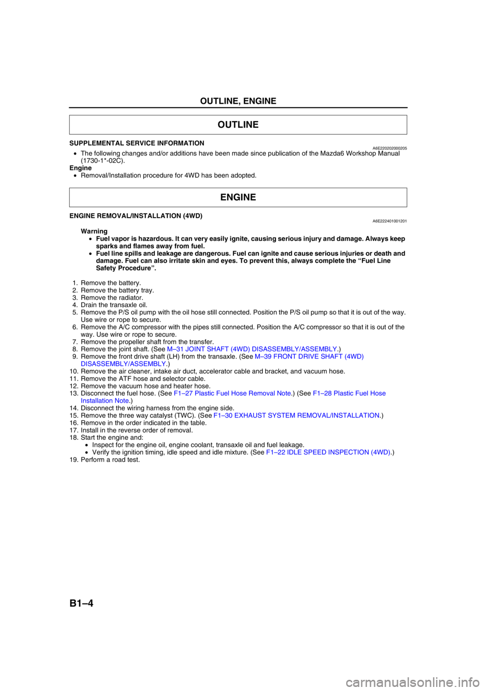
SUPPLEMENTAL SERVICE INFORMATIONA6E220202000205•The following changes and/or additions have been made since publication of the Mazda6 Workshop Manual
(1730-1*-02C).
Engine
•Removal/Installation procedure for 4WD has been adopted.
End Of Sie
ENGINE REMOVAL/INSTALLATION (4WD)A6E222401001201
Warning
•Fuel vapor is hazardous. It can very easily ignite, causing serious injury and damage. Always keep
sparks and flames away from fuel.
•Fuel line spills and leakage are dangerous. Fuel can ignite and cause serious injuries or death and
damage. Fuel can also irritate skin and eyes. To prevent this, always complete the “Fuel Line
Safety Procedure”.
1. Remove the battery.
2. Remove the battery tray.
3. Remove the radiator.
4. Drain the transaxle oil.
5. Remove the P/S oil pump with the oil hose still connected. Position the P/S oil pump so that it is out of the way.
Use wire or rope to secure.
6. Remove the A/C compressor with the pipes still connected. Position the A/C compressor so that it is out of the
way. Use wire or rope to secure.
7. Remove the propeller shaft from the transfer.
8. Remove the joint shaft. (See M–31 JOINT SHAFT (4WD) DISASSEMBLY/ASSEMBLY.)
9. Remove the front drive shaft (LH) from the transaxle. (See M–39 FRONT DRIVE SHAFT (4WD)
DISASSEMBLY/ASSEMBLY.)
10. Remove the air cleaner, intake air duct, accelerator cable and bracket, and vacuum hose.
11. Remove the ATF hose and selector cable.
12. Remove the vacuum hose and heater hose.
13. Disconnect the fuel hose. (See F1–27 Plastic Fuel Hose Removal Note.) (See F1–28 Plastic Fuel Hose
Installation Note.)
14. Disconnect the wiring harness from the engine side.
15. Remove the three way catalyst (TWC). (See F1–30 EXHAUST SYSTEM REMOVAL/INSTALLATION.)
16. Remove in the order indicated in the table.
17. Install in the reverse order of removal.
18. Start the engine and:
•Inspect for the engine oil, engine coolant, transaxle oil and fuel leakage.
•Verify the ignition timing, idle speed and idle mixture. (See F1–22 IDLE SPEED INSPECTION (4WD).)
19. Perform a road test.
OUTLINE
ENGINE
Page 27 of 909

ENGINE
B1–5
B1
6
5
4
3
1
2
74.5—104.9
{7.6—10.6, 55.0—76.6}
N·m {kgf·m, ft·lbf} 85.3—116.6
{8.7—11.8, 62.9—85.9}58.8—80.4
{6.0—8.1, 43.3—58.5} 74.5—104.9
{7.6—10.6,
55.0—76.6}66.6—93.1
{6.8—9.4, 49.2—67.9}
66.6—93.1
{6.8—9.4,
49.2—67.9}58.8—80.4
{6.0—8.1, 43.3—58.5}
8.0—11.5 N·m
{81.6—117.2 kgf·cm,
70.9—101.7 in·lbf}
A6E2213W001
1 No.1 Engine mount rubber
(See B1–6 No.1 Engine Mount Rubber Removal
Note)
(See B1–9 No.1 Engine Mount Rubber Installation
Note)
2 No.1 Engine mount bracket
(See B1–9 No.1 Engine Mount Bracket Installation
Note)
3 No.4 Engine mount bracket and No.4 Engine mount
rubber
(See B1–6 No.4 Engine Mount Bracket and No.4
Engine Mount Rubber Removal Note)
(See B1–8 No.4 Engine Mount Bracket and No.4
Engine Mount Rubber Installation Note)4 Engine ground
5 No.3 Engine joint bracket
(See B1–8 No.3 Engine Joint Bracket Installation
Note)
6 Engine, transaxle
Page 28 of 909

B1–6
ENGINE
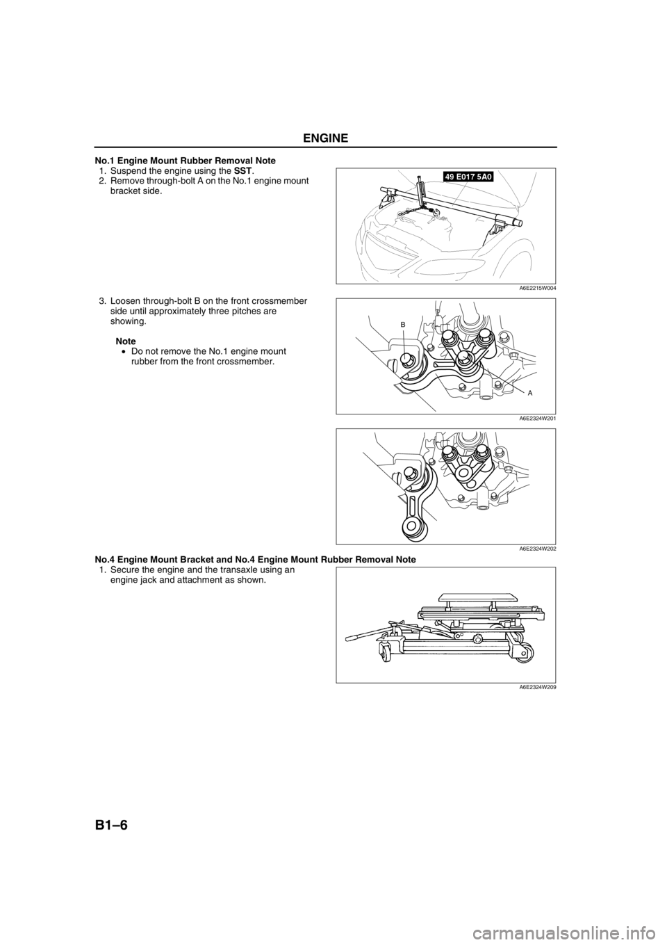
No.1 Engine Mount Rubber Removal Note
1. Suspend the engine using the SST.
2. Remove through-bolt A on the No.1 engine mount
bracket side.
3. Loosen through-bolt B on the front crossmember
side until approximately three pitches are
showing.
Note
•Do not remove the No.1 engine mount
rubber from the front crossmember.
No.4 Engine Mount Bracket and No.4 Engine Mount Rubber Removal Note
1. Secure the engine and the transaxle using an
engine jack and attachment as shown.
A6E2215W004
A B
A6E2324W201
A6E2324W202
A6E2324W209
Page 29 of 909

ENGINE
B1–7
B1
2. Remove the SST.
3. Secure the engine and the transaxle using a
hoist.
4. Remove the No.4 engine mount bracket and
engine mount rubber together as a unit.
A6E2215W004
A6E2324W203
A6E2324W204
Page 30 of 909

B1–8
ENGINE
No.3 Engine Joint Bracket Installation Note
1. Tighten the No.3 engine mount bracket stud bolt.
Tightening torque
7.0—13 N·m {71.4—132.5 kgf·cm, 62.0—115.0
in·lbf}
2. Tighten the No.3 engine joint bracket bolt and nut
in the order as shown.
Tightening torque
74.5—104.9 N·m {7.6—10.6 kgf·m, 55.0—76.6
ft·lbf}
No.4 Engine Mount Bracket and No.4 Engine Mount Rubber Installation Note
1. Tighten the No.4 engine mount bracket and No.4
engine mount rubber bolt and nut in the order as
shown.
2. Secure the engine and the transaxle using an
engine jack and attachment as shown.
No.3
ENGINE
MOUNT
BRACKET
STUD
BOLT
A6E2215W011
12
A6E2316W111
Bolt or nut No.Tightening torque
(N·m {kgf·m, ft·lbf})
1, 2, 358.8—80.4 {6.0—8.1, 43.3—58.5}
4, 5, 666.6—93.1 {6.8—9.4, 49.2—67.9}
5431
2
6
A6E2324W206
A6E2324W209