MAZDA 6 2002 Suplement Repair Manual
Manufacturer: MAZDA, Model Year: 2002, Model line: 6, Model: MAZDA 6 2002Pages: 909, PDF Size: 17.16 MB
Page 61 of 909

B2–30
ENGINE
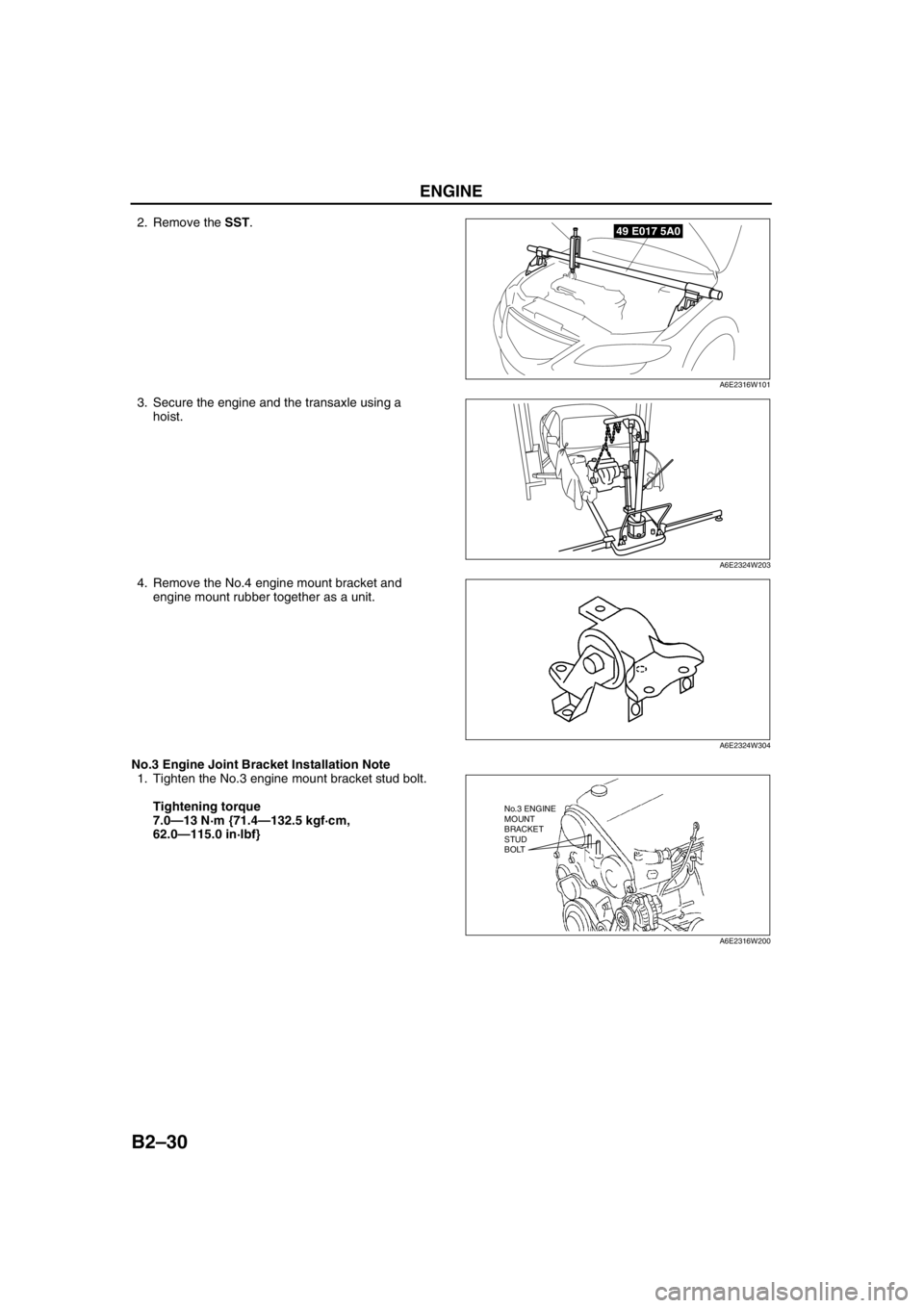
2. Remove the SST.
3. Secure the engine and the transaxle using a
hoist.
4. Remove the No.4 engine mount bracket and
engine mount rubber together as a unit.
No.3 Engine Joint Bracket Installation Note
1. Tighten the No.3 engine mount bracket stud bolt.
Tightening torque
7.0—13 N·m {71.4—132.5 kgf·cm,
62.0—115.0 in·lbf}49 E017 5A0
A6E2316W101
A6E2324W203
A6E2324W304
No.3 ENGINE
MOUNT
BRACKET
STUD
BOLT
A6E2316W200
Page 62 of 909

ENGINE
B2–31
B2
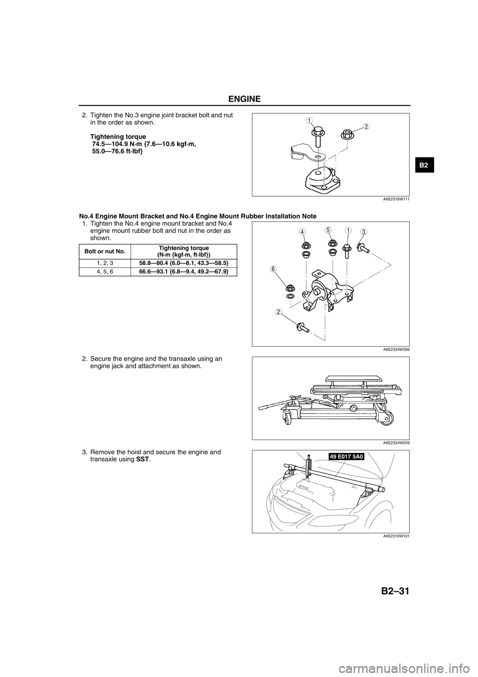
2. Tighten the No.3 engine joint bracket bolt and nut
in the order as shown.
Tightening torque
74.5—104.9 N·m {7.6—10.6 kgf·m,
55.0—76.6 ft·lbf}
No.4 Engine Mount Bracket and No.4 Engine Mount Rubber Installation Note
1. Tighten the No.4 engine mount bracket and No.4
engine mount rubber bolt and nut in the order as
shown.
2. Secure the engine and the transaxle using an
engine jack and attachment as shown.
3. Remove the hoist and secure the engine and
transaxle using SST.12
A6E2316W111
Bolt or nut No.Tightening torque
(N·m {kgf·m, ft·lbf})
1, 2, 358.8—80.4 {6.0—8.1, 43.3—58.5}
4, 5, 666.6—93.1 {6.8—9.4, 49.2—67.9}
5431
2
6
A6E2324W306
A6E2324W209
49 E017 5A0
A6E2316W101
Page 63 of 909

B2–32
ENGINE
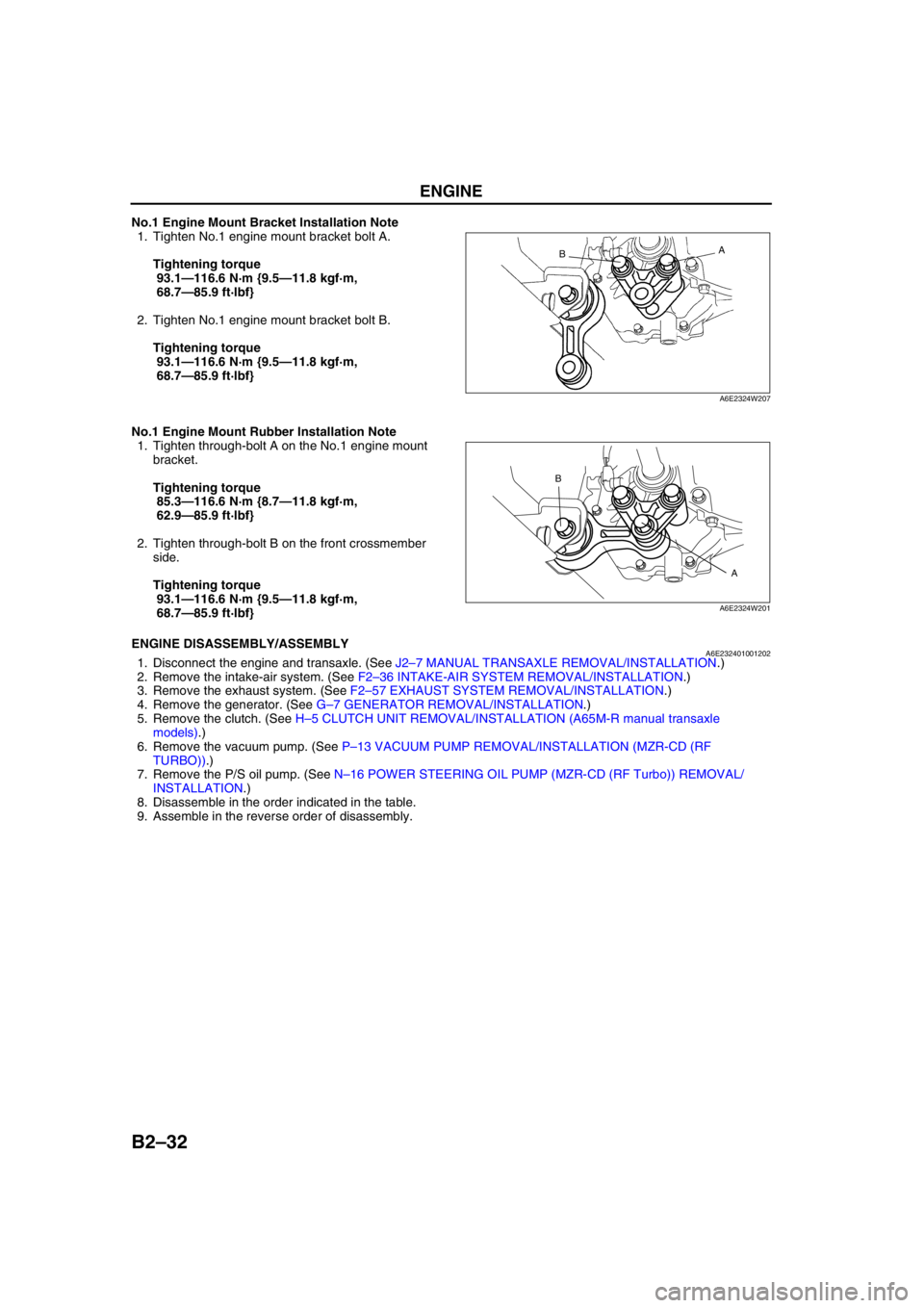
No.1 Engine Mount Bracket Installation Note
1. Tighten No.1 engine mount bracket bolt A.
Tightening torque
93.1—116.6 N·m {9.5—11.8 kgf·m,
68.7—85.9 ft·lbf}
2. Tighten No.1 engine mount bracket bolt B.
Tightening torque
93.1—116.6 N·m {9.5—11.8 kgf·m,
68.7—85.9 ft·lbf}
No.1 Engine Mount Rubber Installation Note
1. Tighten through-bolt A on the No.1 engine mount
bracket.
Tightening torque
85.3—116.6 N·m {8.7—11.8 kgf·m,
62.9—85.9 ft·lbf}
2. Tighten through-bolt B on the front crossmember
side.
Tightening torque
93.1—116.6 N·m {9.5—11.8 kgf·m,
68.7—85.9 ft·lbf}
End Of SieENGINE DISASSEMBLY/ASSEMBLYA6E2324010012021. Disconnect the engine and transaxle. (See J2–7 MANUAL TRANSAXLE REMOVAL/INSTALLATION.)
2. Remove the intake-air system. (See F2–36 INTAKE-AIR SYSTEM REMOVAL/INSTALLATION.)
3. Remove the exhaust system. (See F2–57 EXHAUST SYSTEM REMOVAL/INSTALLATION.)
4. Remove the generator. (See G–7 GENERATOR REMOVAL/INSTALLATION.)
5. Remove the clutch. (See H–5 CLUTCH UNIT REMOVAL/INSTALLATION (A65M-R manual transaxle
models).)
6. Remove the vacuum pump. (See P–13 VACUUM PUMP REMOVAL/INSTALLATION (MZR-CD (RF
TURBO)).)
7. Remove the P/S oil pump. (See N–16 POWER STEERING OIL PUMP (MZR-CD (RF Turbo)) REMOVAL/
INSTALLATION.)
8. Disassemble in the order indicated in the table.
9. Assemble in the reverse order of disassembly.
A
B
A6E2324W207
A B
A6E2324W201
Page 64 of 909

ENGINE
B2–33
B2
.
A/C Compressor Bracket Installation Note
1. Tighten the A/C compressor bracket bolts in the
order shown.
Tightening torque
38—51 N·m {3.8—5.3 kgf·m, 28—38 ft·lbf}
End Of Sie
N·m { kgf·m, ft·lbf} 38—51
{3.8—5.3, 28—38}
1
2
A6E2324W105
1 A/C compressor bracket
(See B2–33 A/C Compressor Bracket Installation
Note)2 Seal plate
43
1
2
A6E2324W106
Page 65 of 909

D–1
D
DLUBRICATION SYSTEM
OUTLINE................................................................ D-2
OUTLINE OF CONSTRUCTION.......................... D-2
SPECIFICATIONS ............................................... D-2
STRUCTURAL VIEW ...........................................D-4
LUBRICATION SYSTEM........................................ D-5
LUBRICATION FLOW CHART ............................ D-5
OUTLINE................................................................ D-6
SUPPLEMENTAL SERVICE INFORMATION .....D-6
LUBRICATION SYSTEM........................................ D-6
LOCATION INDEX ............................................... D-6
OIL PRESSURE INSPECTION..............................D-7
OIL PRESSURE INSPECTION............................ D-7
ENGINE OIL........................................................... D-8
ENGINE OIL INSPECTION.................................. D-8
ENGINE OIL REPLACEMENT.............................D-8
OIL FILTER............................................................. D-9
OIL FILTER REPLACEMENT ..............................D-9
OIL COOLER.......................................................... D-9
OIL COOLER REMOVAL/INSTALLATION ..........D-9
OIL PAN................................................................ D-10
OIL PAN REMOVAL/INSTALLATION................ D-10 FEATURES
SERVICE
Page 66 of 909

D–2
OUTLINE
OUTLINE OF CONSTRUCTIONA6E330202000201•The construction and the operation of the oil cooler and the oil filter for the new Mazda6 (GG, GY) MZR-CD (RF
Turbo) engine model is the same as the current Mazda MPV (LW) MZR-CD (RF Turbo) engine model. (See
Mazda MPV Workshop Manual Supplement 1737-1*-02D.)
•The construction and the operation of the lubrication system except for the oil cooler and oil filter for the new
Mazda6 (GG, GY) MZR-CD (RF Turbo) engine model is the same as the current Mazda 626, 626 Station
Wagon (GF, GW) RF Turbo engine model. (European specs.) (See Mazda 626, 626 Station Wagon RF Turbo
Workshop Manual Supplement 1614-10-98D.)
•The construction and the operation of the lubrication system for the new Mazda6 (GG, GY) L8, LF, and L3
engine models is the same as the current Mazda6 (GG) engine model L8, LF, and L3 engine models. (See
Mazda6 Training Manual 3359-1*-02C, Mazda6 Workshop Manual 1730-1*-02C.)
End Of Sie
SPECIFICATIONSA6E330202000202Gasoline engine
* : Always verify the oil level with the dipsticks since the engine oil capacity differs according to dipstick
specifications. (See Mazda6 Workshop Manual 1730-1*-02C Section D.)
Recommended Engine Oil (Gasoline Engine)
•The maintenance intervals on the scheduled maintenance table (See GI–8 SCHEDULED MAINTENANCE
TABLE) can only be supported with the use of following oils.
OUTLINE
ItemSpecification
New
Mazda6
(GG, GY)Current
Mazda6
(GG)New
Mazda6
(GG, GY)Current
Mazda6
(GG)New
Mazda6
(GG, GY)Current
Mazda6
(GG)
L8 LF L3*
Lubrication system Force-fed type
Oil coolerWater-cooled
Oil pressure
(approximate quantity)
[oil temperature: 100°C
{212°F}](kPa {kgf/cm
2, psi})
min [rpm]234—521
{2.39—5.31, 33.9—75.5}
[3,000]395—649
{4.03—6.61,
57.3—94.1}
[3,000]
Oil pumpType Trochoid gear type
Relief pressure
(approximate
quantity) (kPa {kgf/cm
2,
psi})500—600
{5.09—6.11, 72.6—87.0}
Oil filterType Full-flow, Paper element
Bypass pressure
(approximate
quantity)(kPa kgf/cm
2, psi})80—120
{0.9—1.2, 12.8—17.0}
Oil capacity
(approximate
quantity)Total
(dry engine)(L {US qt, lmp qt}) 4.6 {4.8, 4.0} Dipstick A: 4.2 {4.4, 3.7}
Dipstick B: 5.1 {5.4, 4.5}
Oil replacement (L {US qt, lmp qt}) 3.9 {4.0, 3.4} Dipstick A: 3.1 {3.3, 2.7}
Dipstick B: 4.0 {4.2, 3.5}
Oil and oil filter
replacement(L {US qt, lmp qt}) 4.3 {4.5, 3.8} Dipstick A: 3.5 {3.7, 3.1}
Dipstick B: 4.4 {4.6, 3.9}
ItemSpecification
New Mazda6
(GG, GY), Current Mazda6
(GG)New Mazda6
(GG, GY), Current Mazda6
(GG)
L8, LF, L3
Engine oil GradeAPI SL
ACEA A3
Viscosity (SAE) 5W-30, 10W-40 5W-20
RemarksMazda genuine Dexelia oil e.g. —
Page 67 of 909

OUTLINE
D–3
D
Diesel engine
Bold frames: New specifications
Recommended Engine Oil (Diesel Engine)
•The maintenance intervals on the scheduled maintenance table (See GI–8 SCHEDULED MAINTENANCE
TABLE) can only be supported with the use of following oils.
Bold frames: New specifications
End Of Sie
ItemSpecification
New Mazda6
(GG, GY)Current
Mazda 626, 626
Station Wagon
(GF, GW)Current
Mazda MPV
(LW)
MZR-CD (RF Turbo) RF TurboMZR-CD (RF
Turbo)
Lubrication system Force-fed type—
Oil cooler Water-cooled—
Oil pressure
(approximate quantity)
[oil temperature: 100°C {212°F}](kPa {kgf/cm
2, psi})
min [rpm]147 {1.5, 21} [1,000],
343 {3.5, 50} [3,000]—
Oil pumpType Trochoid gear type—Trochoid gear type
Relief pressure
(approximate
quantity)(kPa {kgf/cm
2, psi})
[rpm]580—700
{5.9—7.1,
84.1—101.5}
[3,000]—580—700
{5.9—7.1,
84.1—101.5}
[3,000]
Oil filterTypeFull-flow,
Paper element—Full-flow,
Paper element
Bypass pressure
(approximate
quantity)(kPa kgf/cm
2, psi})78—118
{0.8—1.2,
11.3—17.1} —78—118
{0.8—1.2,
11.3—17.1}
Oil capacity
(approximate
quantity)Total
(dry engine)(L {US qt, lmp qt}) 5.5 {5.8, 4.8} 5.4 {5.7, 4.8} —
Oil replacement (L {US qt, lmp qt}) 4.8 {5.1, 4.2} 4.5 {4.8, 4.0}—
Oil and oil filter
replacement(L {US qt, lmp qt}) 5.0 {5.3 ,4.4} 4.7 {5.0, 4.1} —
ItemSpecification
New Mazda6
(GG, GY)Current
Mazda 626, 626
Station Wagon
(GF, GW)
MZR-CD (RF Turbo) RF Turbo
Engine oil GradeAPI CF CD, CE, CF-4 CD
ACEA B1 or B3 B3 B3 or B4—
Viscosity (SAE) 5W-30 10W-40 5W-30, 10W-30 5W-30, 10W-30
RemarksMazda genuine
Dexelia oil e.g.——
Page 68 of 909

D–4
OUTLINE
STRUCTURAL VIEWA6E330202000203MZR-CD (RF Turbo)
.
End Of Sie
8
7
5
4
3
1
2
6
9
A6E330W001
1 Oil pressure switch
2 Oil filter
3Oil cooler
4Oil pan
5 Oil filter adapter6 Oil pump
7 Oil strainer
8 Turbocharger
9 Vaccum pump
Page 69 of 909

LUBRICATION SYSTEM
D–5
D
LUBRICATION FLOW CHARTA6E333014100202MZR-CD (RF Turbo)
.
End Of Sie
LUBRICATION SYSTEM
98
7
5
4
3
12
10
17
15
16
14
13
11
12
6
18
12
A6E3300W002
1 Oil pan
2 Oil strainer
3 Oil pump
4 Oil cooler
5 Oil filter
6 Main bearing
7 Crankshaft
8 Connecting rod bearing
9 Oil jet valve10 Piston
11 Oil pressure switch
12 Orifice
13 Camshaft
14 Rocker arm shaft
15 Rocker arm, rocker arm bridge
16 Vaccum pump
17 Turbocharger
18 Cylinder head
Page 70 of 909

D–6
OUTLINE, LUBRICATION SYSTEM
SUPPLEMENTAL SERVICE INFORMATIONA6E330202000204•The following changes and/or additions have been made since publication of the Mazda6 Workshop Manual
(1730-1*-02C).
Oil pressure
•Inspection procedure has been adopted. (MZR-CD (RF Turbo) engine model)
Engine oil
•Inspection procedure has been adopted. (MZR-CD (RF Turbo) engine model)
•Replacement procedure has been adopted. (MZR-CD (RF Turbo) engine model)
Oil filter
•Replacement procedure has been adopted. (MZR-CD (RF Turbo) engine model)
Oil cooler
•Removal/Installation procedure has been adopted. (MZR-CD (RF Turbo) engine model)
Oil pan
•Removal/Installation procedure has been adopted. (MZR-CD (RF Turbo) engine model)
End Of Sie
LOCATION INDEXA6E333014100201MZR-CD (RF Turbo)
.
End Of Sie
OUTLINE
LUBRICATION SYSTEM
4
3
1
2
A6E3300W003
1 Oil pressure switch
(See D–7 OIL PRESSURE INSPECTION)
2 Oil filter
(See D–9 OIL FILTER REPLACEMENT)3 Oil cooler
(See D–9 OIL COOLER REMOVAL/
INSTALLATION)
4 Oil pan
(See D–10 OIL PAN REMOVAL/INSTALLATION)