MAZDA 6 2002 Suplement Owners Manual
Manufacturer: MAZDA, Model Year: 2002,
Model line: 6,
Model: MAZDA 6 2002
Pages: 909, PDF Size: 17.16 MB
MAZDA 6 2002 Suplement Owners Manual
6 2002
MAZDA
MAZDA
https://www.carmanualsonline.info/img/28/57057/w960_57057-0.png
MAZDA 6 2002 Suplement Owners Manual
Trending: tires, cooling, ad blue, dimensions, timing belt, tire size, water pump
Page 91 of 909

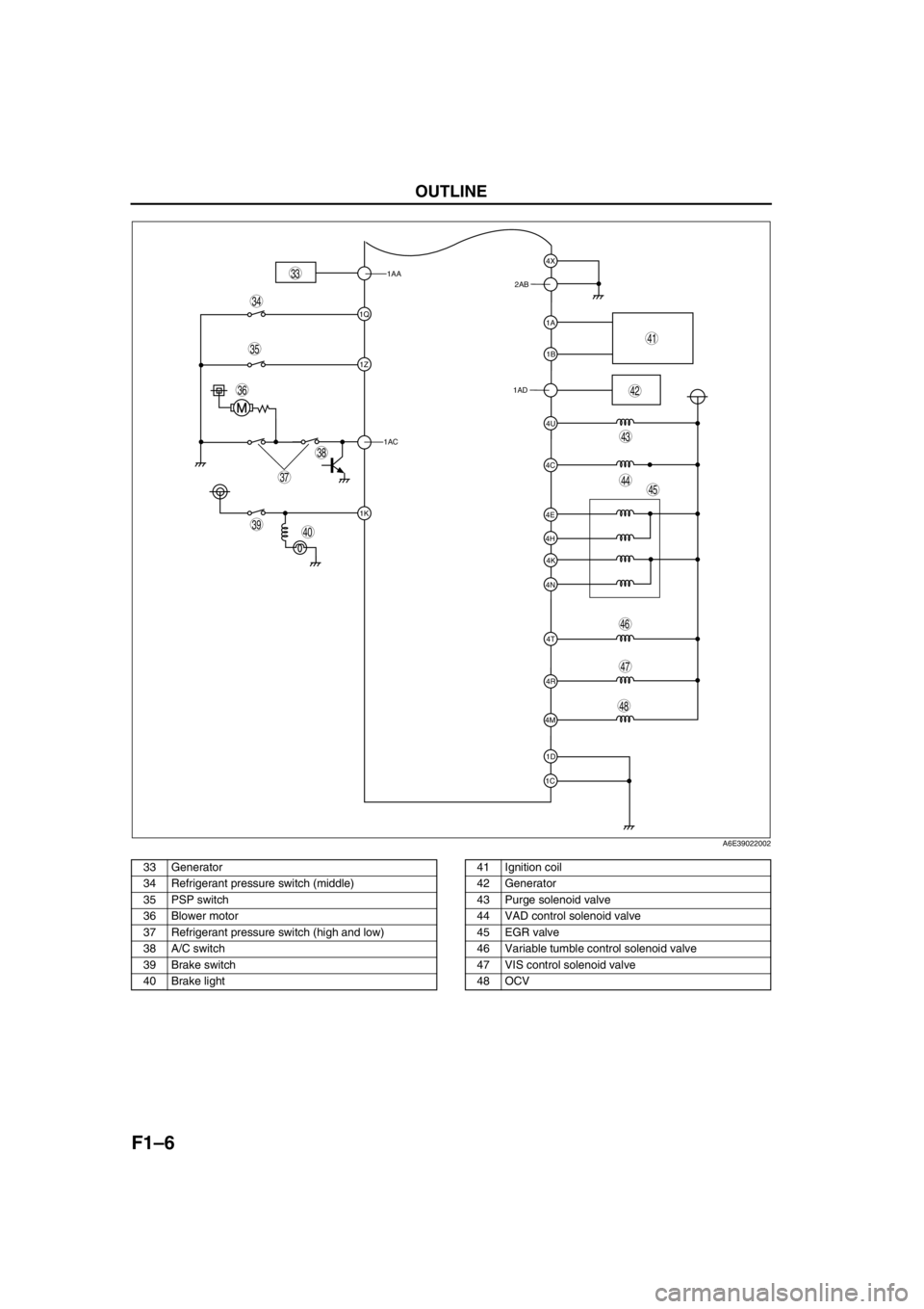
OUTLINE
F1–3
F1
CONTROL SYSTEM DIAGRAM (4WD)A6E390218881204
.
* : Equipped for L3 engine modelEnd Of Sie
9
8
7
54
3
10
19
18
17
15
16
14
13
11
12
20
29
28
27
25
26
24
23
21
22
30
3938
3735
33
36
31
32
40
6
1
2
3441
A6E39022000
1PCM
2 Ignition coil
3 Generator
4* VAD shutter valve
5 Air cleaner
6 MAF sensor
7* VAD shutter valve actuator
8* VAD control solenoid valve
9* Vacuum chamber
10* VAD check valve (one-way)
11 IAC valve
12 Purge solenoid valve
13 TP sensor
14 MAP sensor
15* VIS control solenoid valve
16 Variable tumble control solenoid valve
17* VIS shutter valve actuator
18* VIS shutter valve
19 VTCS shutter valve actuator
20 VTCS shutter valve
21 Fuel injector22* OCV
23 CMP sensor
24 EGR valve
25 Knock sensor
26 ECT sensor
27 PCV valve
28 CKP sensor
29 HO2S (front)
30 HO2S (rear)
31 Charcoal canister
32 Check valve (two-way)
33 Pressure regulator
34 Fuel filter (high-pressure)
35 Fuel pump
36 Fuel filter (low-pressure)
37 Fuel tank
38 Rollover valve
39 Pulsation damper
40 Fuel pump (transfer)
41 To PCM
Page 92 of 909
F1–4
OUTLINE
CONTROL SYSTEM WIRING DIAGRAM (4WD)A6E390218881205With Immobilizer System
.
2Y
2Z
2AC
1AB
1Y
2K
2A
1J
1G
1M
2E
1P
2H
2U
2R
2P
2S
2D
2G
2J
2M4Z
4W
4AD
4AA
4G
4J
4A
4D
2X
4O
4B
4L
4F
4Q
2T
2Q
2W
4I
9
87
5
4
3
10
19
18
17
15
16
14
13
11
12
20
29
28
27
25
26
24
23
21
22
30
6
1
2
3132
A6E39022001
1 HO2S (front)
2 HO2S (rear)
3 TP sensor
4 MAP sensor
5 BARO sensor6ECT sensor
7 MAF/IAT sensor
8 IAT sensor
9 MAF sensor
10 Controller area network (CAN)
Page 93 of 909
OUTLINE
F1–5
F1
11 Knock sensor
12 CKP sensor
13 CMP sensor
14 Fuel injector No.1
15 Fuel injector No.2
16 Fuel injector No.3
17 Fuel injector No.4
18 IAC valve
19 Oxygen sensor heater (front)
20 Oxygen sensor heater (rear)
21 A/C relay22 Cooling fan relay
23 Cooling fan relay
24 Cooling fan relay
25 TR switch
26 Fuel pump relay
27 Coil
28 Security light
29 Ignition switch
30 Main relay
31 TR switch
32 Starter relay
Page 94 of 909
F1–6
OUTLINE
.
1AA
1Q
1Z
1AC
1K
1C1D 4M4R 4N4K 4H4E
4T 4C4U 1AD1B 1A 2AB4X
39
38
37
35
36
33
40
45
46
44
43
41
42
34
48
47
A6E39022002
33 Generator
34 Refrigerant pressure switch (middle)
35 PSP switch
36 Blower motor
37 Refrigerant pressure switch (high and low)
38 A/C switch
39 Brake switch
40 Brake light41 Ignition coil
42 Generator
43 Purge solenoid valve
44 VAD control solenoid valve
45 EGR valve
46 Variable tumble control solenoid valve
47 VIS control solenoid valve
48 OCV
Page 95 of 909
OUTLINE
F1–7
F1
Without Immobilizer system
.
2Y
2Z
2AC
1AB
1Y
2K
2A
1J
1G
1M
2E
1P
2H
2U
2R
2P
2S
2D
2G
2J
2M4Z
4W
4AD
4AA
4G
4J
4A
4D
2X
4O
4B
4L
4F
4P
9
87
5
4
3
10
19
18
17
15
16
14
13
11
12
20
25
26
24
23
21
226
1
2
28
27
A6E39022003
1 HO2S (front)
2 HO2S (rear)
3 TP sensor
4 MAP sensor
5 BARO sensor
6ECT sensor
7 MAF/IAT sensor8 IAT sensor
9 MAF sensor
10 Controller area network (CAN)
11 Knock sensor
12 CKP sensor
13 CMP sensor
14 Fuel injector No.1
Page 96 of 909
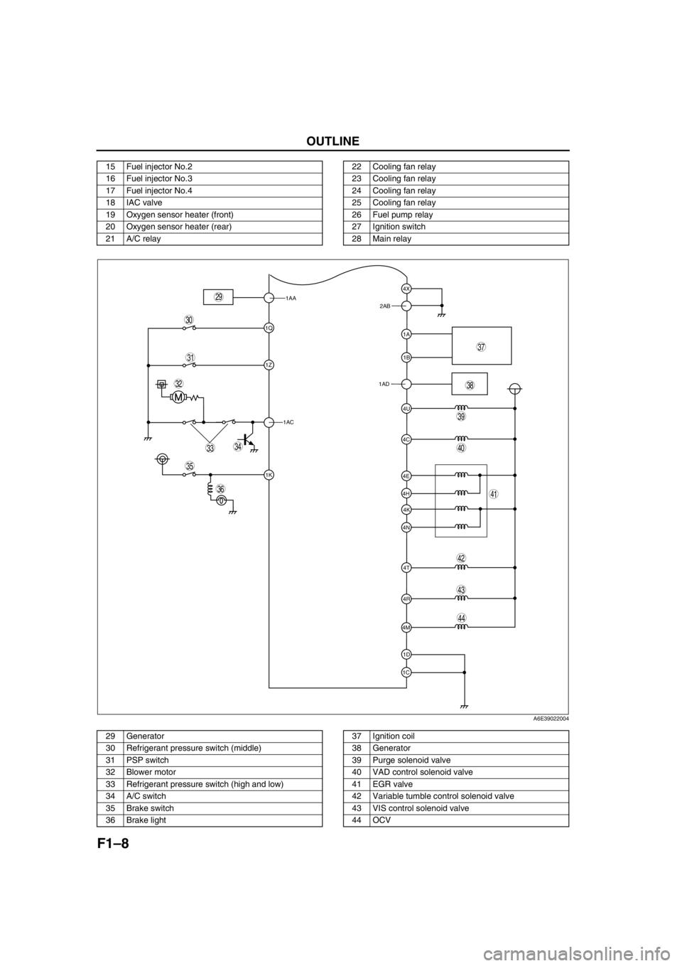
F1–8
OUTLINE
.
15 Fuel injector No.2
16 Fuel injector No.3
17 Fuel injector No.4
18 IAC valve
19 Oxygen sensor heater (front)
20 Oxygen sensor heater (rear)
21 A/C relay22 Cooling fan relay
23 Cooling fan relay
24 Cooling fan relay
25 Cooling fan relay
26 Fuel pump relay
27 Ignition switch
28 Main relay
1AA
1Q
1Z
1AC
1K
1C1D 4M4R 4N4K 4H4E
4T 4C4U 1AD1B 1A 2AB4X
39
38
37
35
36
33
31
32
40
44
43
41
42
34
29
30
A6E39022004
29 Generator
30 Refrigerant pressure switch (middle)
31 PSP switch
32 Blower motor
33 Refrigerant pressure switch (high and low)
34 A/C switch
35 Brake switch
36 Brake light37 Ignition coil
38 Generator
39 Purge solenoid valve
40 VAD control solenoid valve
41 EGR valve
42 Variable tumble control solenoid valve
43 VIS control solenoid valve
44 OCV
Page 97 of 909
FUEL SYSTEM
F1–9
F1
End Of Sie
OUTLINEA6E391201006201•The fuel system is essentially carried over from that of the current Mazda6 (GG), except for the following. (See
Mazda6 Training Manual 3359-1*-02C.)
—A saddle type fuel tank has been adopted.
—A fuel pump (transfer) for fuel transmission has been added.
End Of Sie
STRUCTURAL VIEWA6E391201006202
.
End Of Sie
FUEL SYSTEM
7
5
4
3
6
1
2
A6E39122001
1 Fuel gauge sender sub-unit
2 Quick release connector (fuel tank side, transfer
hose part)
3 Non-return valve4 Quick release connector (fuel tank side, main fuel
pipe part)
5 Fuel tank
6 Fuel pump unit
7 Filler cap
Page 98 of 909
F1–10
FUEL SYSTEM
SYSTEM DIAGRAMA6E391201006203
.
End Of Sie
FUEL PUMP (TRANSFER)A6E391213350201Function
•The fuel tank for 4WD is saddle type. Fuel in the fuel gauge sender sub-unit side (right side) is pumped to the
left side of the fuel tank using the fuel pump (transfer).
Structure
•The fuel pump (transfer) is integrated into the fuel pump unit and it cannot be separately disassembled.
•The fuel pump (transfer) is composed of a relief valve and fuel jet pump.
87
5
4
3
6
1
2
:
9
10
A6E39122002
1 Filler cap
2 Pressure regulator
3 Fuel pump (transfer)
4 Fuel filter (high-pressure)
5Fuel pump6 Fuel filter (low-pressure)
7 Fuel pump unit
8 Pulsation damper
9 Fuel injector
10 Fuel flow
Page 99 of 909
FUEL SYSTEM
F1–11
F1
Operation
•The fuel jet pump (venturi) is installed in the return passage from the pressure regulator, and fuel in the fuel
tank is pumped to the left side from the right side using the vacuum generated in the passage.
•When the return fuel pressure exceeds a specified value, the relief valve is opened. The relief valve delivers the
return fuel directly to the fuel tank. In this way, pressure of the return fuel passing through the fuel jet pump is
kept constantly below the specified value.
.
End Of Sie
9
8
7
54
3
10
14
13
11
12
6
1
2
:
:
2
15
A6E39122003
1 Fuel pump unit
2 Fuel pump (transfer)
3 Fuel injector
4 Fuel tank (left side)
5 Fuel tank (right side)
6 Relief valve
7 Discharge outlet
8 From pressure regulator9 From fuel tank (right side)
10 Fuel jet pump
11 To fuel tank (left side)
12 Fuel jet pump
13 From fuel tank (left side)
14 Fuel flow
15 Pumped fuel flow
Page 100 of 909

F1–12
FUEL SYSTEM
QUICK RELEASE CONNECTOR (FUEL TANK SIDE, TRANSFER HOSE PART)A6E391242692201Function
•The quick release connector makes disconnecting and connecting of fuel hoses and fuel pipes easy.
Structure
•The quick release connector is adopted for the transfer hose part of the fuel tank side.
•The quick release connector is composed of a retainer, O-ring and other parts. The quick release connector
and plastic fuel hose are integrated and cannot be disconnected.
•The retainer and quick release connector are integrated and cannot be disconnected.
•An SST is not required to uncouple this type of quick release connector.
.
Operation
•Squeeze the tabs of the retainer to unlock and disconnect the quick release connector from the fuel pipe.
•A click is heard when the tabs of the retainer are pushed correctly into the lock point of the quick release
connector.
.
End Of Sie
3
1
2
A6E39122010
1Tab
2 Quick release connector3 Disconnect
7
5
4
3
6
1
21
A6E39122011
1 O-ring
2 Lock point
3 Disconnect
4Fuel hose5 Quick release connector
6 Retainer
7 Fuel pipe
Trending: fuses, engine, ground clearance, check engine, jump start, steering wheel, wheel size


