MAZDA 6 2002 Workshop Manual Suplement
Manufacturer: MAZDA, Model Year: 2002, Model line: 6, Model: MAZDA 6 2002Pages: 909, PDF Size: 17.16 MB
Page 871 of 909

U–8
LOCATION INDEX
BASIC SYSTEMA6E850001040201
.
End Of Sie
LOCATION INDEX
8
75
4
3
1
2
6
4
L.H.D.
A6E85002001
8
7
5
43
1
2
6
4
R.H.D.
A6E85002002
1 Blower unit
2 Air filter
3A/C unit
(See U–10 A/C UNIT REMOVAL/INSTALLATION)
4 Rear heat duct
5 A/C compressor
(See U–11 A/C COMPRESSOR REMOVAL/
INSTALLATION)6 Condenser
(See U–12 CONDENSER REMOVAL/
INSTALLATION)
7Heater hose
8 Refrigerant lines
(See U–13 REFRIGERANT LINES REMOVAL/
INSTALLATION)
Page 872 of 909

LOCATION INDEX
U–9
U
CONTROL SYSTEMA6E850001040202
.
End Of Sie
1
2
3
A6E85002003
1 Water heater unit
(See U–15 WATER HEATER UNIT REMOVAL/
INSTALLATION)
2 Fuel pump (water heater system)
(See U–16 FUEL PUMP (WATER HEATER
SYSTEM) INSPECTION)3 Climate control unit
(See U–16 CLIMATE CONTROL UNIT
INSPECTION)
Page 873 of 909

U–10
BASIC SYSTEM
A/C UNIT REMOVAL/INSTALLATIONA6E8516611302011. Disconnect the negative battery cable.
2. Discharge the refrigerant from the system.
3. Drain the engine coolant.
4. Remove the dashboard.
5. Remove the theft-deterrent control module.
Caution
•If moisture or foreign material enters the refrigeration cycle, cooling ability will be lowered and
abnormal noise will occur. Always immediately plug open fittings after removing any refrigeration
cycle parts to keep moisture or foreign material out of the cycle.
6. Remove in the order indicated in the table. Do not allow compressor oil to spill.
.
BASIC SYSTEM
1
L.H.D.R.H.D.
3
2
R
R
N·m {kgf·cm, in·lbf} 6.86—9.80
{70.0—99.9,
60.8—86.7}
R
R
3
2
1
4
A6E85162001
1 Heater hose
2 Cooler pipe No.4 (L.H.D.) or cooler pipe No.5
(R.H.D.)
(See U–13 REFRIGERANT LINES REMOVAL/
INSTALLATION) (R.H.D.)
(See U–13 REFRIGERANT LINES REMOVAL/
INSTALLATION)3 Cooler pipe No.3
(See U–13 REFRIGERANT LINES REMOVAL/
INSTALLATION) (R.H.D.)
(See U–13 REFRIGERANT LINES REMOVAL/
INSTALLATION)
4A/C unit
(See U–11 A/C Unit Installation Note)
Page 874 of 909

BASIC SYSTEM
U–11
U
7. Install in the reverse order of removal.
8. Perform the refrigerant system performance test.
A/C Unit Installation Note
1. When installing a new A/C unit or evaporator, add a supplemental amount of ATMOS GU10 compressor oil into
the refrigerant cycle.
Supplemental amount (approximate quantity)
40 ml {40 cc, 1.4 fl oz}
End Of Sie
A/C COMPRESSOR REMOVAL/INSTALLATIONA6E8516614502011. Disconnect the negative battery cable.
2. Discharge the refrigerant from the system.
3. Remove the right side splash shield.
4. Loosen the drive belt and remove it.
Caution
•If moisture or foreign material enters the refrigeration cycle, cooling ability will be lowered and
abnormal noise will occur. Always immediately plug open fittings after removing any refrigeration
cycle parts to keep moisture or foreign material out of the cycle.
5. Remove in the order indicated in the table. Do not
allow compressor oil to spill.
.
6. Install in the reverse order of removal.
7. Adjust the drive belt.
8. Perform the refrigerant system performance test.
A/C Compressor Installation Note
1. Remove the following amount of compressor oil from the new A/C compressor when replacing the A/C
compressor.
Compressor oil to be removed (approximate quantity)
150 ml {150 cc, 5.07 fl oz} – [compressor oil from old A/C compressor + 15 ml {15 cc, 0.5 fl oz}]
End Of Sie
1 Cooler hose (HI)
(See U–13 REFRIGERANT LINES REMOVAL/
INSTALLATION)
2 Cooler hose (LO)
(See U–13 REFRIGERANT LINES REMOVAL/
INSTALLATION)
3 Magnetic clutch connector
4A/C compressor
(See U–11 A/C Compressor Installation Note)
4
3
1
2
N·m {kgf·cm, in·lbf} 6.86—9.80
{70.0—99.9,
60.8—86.7}
R
R
6.86—9.80
{70.0—99.9,
60.8—86.7}
17.6—26.5 N·m
{1.80—2.70 kgf·m,
13.0—19.5 ft·lbf}
A6E85162005
Page 875 of 909

U–12
BASIC SYSTEM
CONDENSER REMOVAL/INSTALLATIONA6E8516614802011. Disconnect the negative battery cable.
2. Discharge the refrigerant from the system.
3. Remove the shroud panel.
Caution
•If moisture or foreign material enters the refrigeration cycle, cooling ability will be lowered and
abnormal noise will occur. Always immediately plug all open fittings after removing any
refrigeration cycle parts to keep moisture or foreign material out of the cycle.
4. Remove in the order indicated in the table. Do not
allow compressor oil to spill.
.
5. Install in the reverse order of removal.
6. Perform the refrigerant system performance test.
Condenser Installation Note
1. When installing a new condenser, add a supplemental amount of ATMOS GU10 compressor oil inlet the
refrigerant cycle.
Supplemental amount (approximate quantity)
35 ml {35 cc, 1.2 fl oz}
End Of Sie
1 Cooler pipe No.1
(See U–13 REFRIGERANT LINES REMOVAL/
INSTALLATION)
(See U–13 REFRIGERANT LINES REMOVAL/
INSTALLATION)
2 Cooler pipe No.2
(See U–13 REFRIGERANT LINES REMOVAL/
INSTALLATION)
(See U–13 REFRIGERANT LINES REMOVAL/
INSTALLATION)
3 Condenser
(See U–12 Condenser Installation Note)
N·m {kgf·cm, in·lbf}
R
3
1
2
6.86—9.80
{70.0—99.9, 60.8—86.7}
R
A6E8516W013
Page 876 of 909

BASIC SYSTEM
U–13
U
REFRIGERANT LINES REMOVAL/INSTALLATIONA6E8516614602011. Remove the battery.
2. Discharge the refrigerant from the system.
3. Remove the washer tank.
4. Remove the air cleaner cover, air cleaner element and air cleaner case. (See F2–36 INTAKE-AIR SYSTEM
REMOVAL/INSTALLATION.)
5. Remove the sedimentor.
6. Remove the No.3 engine mount.
7. Remove the water heater unit.
8. Remove the shroud panel.
9. Remove the right splash shield.
Caution
•If moisture or foreign material enters the refrigeration cycle, cooling ability will be lowered and
abnormal noise will occur. Always immediately plug all open fittings after removing any
refrigeration cycle parts to keep moisture or foreign material out of the cycle.
10. Remove in the order indicated in the table. Do not allow compressor oil to spill.
11. Install in the reverse order of removal.
Page 877 of 909

U–14
BASIC SYSTEM
12. Perform the refrigerant system performance test..
A
BB A
7
4
3
1
2
6
R
A:6.86—9.80 N·m {70.0—99.9 kgf·cm, 60.8—86.7 in·lbf}
R
R
R
R
R
R
R
AA A A
AAA
A
AR
L.H.D.
A
A6E85162006
A
7
5
4
31
2
6
R
A:6.86—9.80 N·m {70.0—99.9 kgf·cm, 60.8—86.7 in·lbf}
R
R
R
RR
R
R
A
A
A A A
A
A
R
R.H.D.
A
AAR
A6E85162007
Page 878 of 909

BASIC SYSTEM, CONTROL SYSTEM
U–15
U
End Of Sie
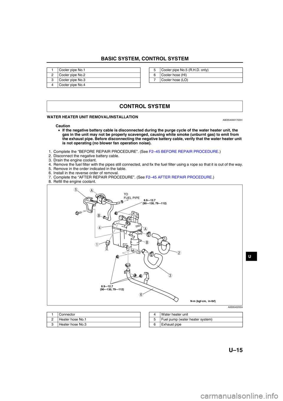
WATER HEATER UNIT REMOVAL/INSTALLATIONA6E854000170201
Caution
•If the negative battery cable is disconnected during the purge cycle of the water heater unit, the
gas in the unit may not be properly scavenged, causing white smoke (unburnt gas) to emit from
the exhaust pipe. Before disconnecting the negative battery cable, verify that the water heater unit
is not operating (no blower fan operation noise).
1. Complete the “BEFORE REPAIR PROCEDURE”. (See F2–45 BEFORE REPAIR PROCEDURE.)
2. Disconnect the negative battery cable.
3. Drain the engine coolant.
4. Remove the fuel filter with the pipes still connected, and fix the fuel filter using a rope so that it is out of the way.
5. Remove in the order indicated in the table.
6. Install in the reverse order of removal.
7. Complete the “AFTER REPAIR PROCEDURE”. (See F2–45 AFTER REPAIR PROCEDURE.)
8. Refill the engine coolant.
.
End Of Sie
1 Cooler pipe No.1
2 Cooler pipe No.2
3 Cooler pipe No.3
4 Cooler pipe No.45 Cooler pipe No.5 (R.H.D. only)
6 Cooler hose (HI)
7 Cooler hose (LO)
CONTROL SYSTEM
A
A
B
B
5
4
3
1
2
6
TO
FUEL PIPE
8.9—12.7
{90—130, 79—112}
N·m {kgf·cm, in·lbf}
8.9—12.7
{90—130, 79—112}
A6E85402004
1 Connector
2 Heater hose No.1
3 Heater hose No.34 Water heater unit
5 Fuel pump (water heater system)
6 Exhaust pipe
Page 879 of 909

U–16
CONTROL SYSTEM
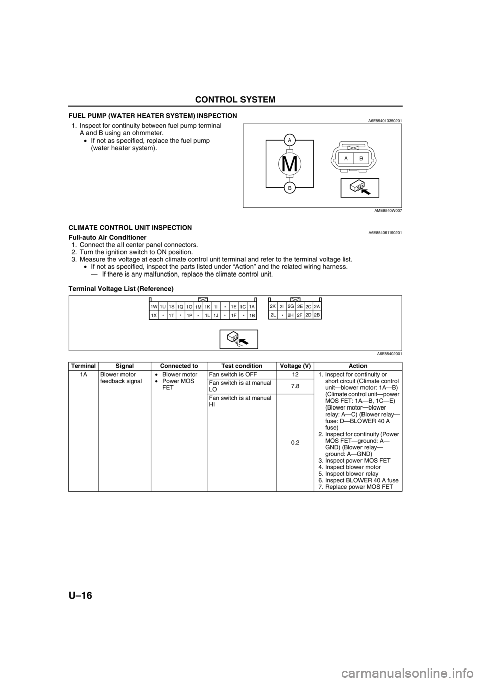
FUEL PUMP (WATER HEATER SYSTEM) INSPECTIONA6E8540133502011. Inspect for continuity between fuel pump terminal
A and B using an ohmmeter.
•If not as specified, replace the fuel pump
(water heater system).
End Of Sie
CLIMATE CONTROL UNIT INSPECTIONA6E854061190201Full-auto Air Conditioner
1. Connect the all center panel connectors.
2. Turn the ignition switch to ON position.
3. Measure the voltage at each climate control unit terminal and refer to the terminal voltage list.
•If not as specified, inspect the parts listed under “Action” and the related wiring harness.
—If there is any malfunction, replace the climate control unit.
Terminal Voltage List (Reference)
AME8540W007
Terminal Signal Connected to Test condition Voltage (V) Action
1A Blower motor
feedback signal•Blower motor
•Power MOS
FETFan switch is OFF 12 1. Inspect for continuity or
short circuit (Climate control
unit—blower motor: 1A—B)
(Climate control unit—power
MOS FET: 1A—B, 1C—E)
(Blower motor—blower
relay: A—C) (Blower relay—
fuse: D—BLOWER 40 A
fuse)
2. Inspect for continuity (Power
MOS FET—ground: A—
GND) (Blower relay—
ground: A—GND)
3. Inspect power MOS FET
4. Inspect blower motor
5. Inspect blower relay
6. Inspect BLOWER 40 A fuse
7. Replace power MOS FET Fan switch is at manual
LO7.8
Fan switch is at manual
HI
0.2
2A
1W
2B 2C
2D 2E
2F 2G
2H 2I 2K
2L
* 1A
1B
* *
* *
* 1X1C 1E
1F * 1I
1K
1M 1O
1P 1Q 1S
1T 1U
1J 1L
A6E85402001
Page 880 of 909

CONTROL SYSTEM
U–17
U
1B +5 V•Air mix actuator
•Airflow mode
actuator
•Solar radiation
sensorIgnition switch at ON
position
5.0•Inspect for short circuit
(Climate control unit— air
mix actuator, airflow mode
actuator, solar radiation
sensor: 1B—B, B, A)
•Inspect air mix actuator
•Inspect airflow mode
actuator
•Inspect solar radiation
sensor
•Inspect terminal voltage of
climate control unit
connector (2H, 2L)
Ignition switch at LOCK
positionBelow 1.0•Replace climate control unit
1C Blower motor
control signalPower MOS FET Fan switch is OFF Below 1.0•Inspect terminal voltage of
climate control unit (1A)
Fan switch is at manual
LO4.1
Fan switch is at manual
HI7.9
1D—— —— —
1E Rear window
defroster SW
signalRear window
defroster relayRear window defroster
switch is off
12•Inspect for continuity or
short circuit (Climate control
unit—rear window defroster
relay: 1E—E)
•Inspect rear window
defroster relay
Rear window defroster
switch is on Below 1.0•Inspect terminal voltage of
climate control unit (2H, 2L)
•Inspect center panel
1F On-board
diagnostic signalA/C check
connectorTerminal A of A/C check
connector is shorted. Below 1.0•Inspect for continuity
(Climate control unit—A/C
check connector: 1F—A)
Other
5.4•Inspect short circuit (Climate
control unit—A/C check
connector: 1F—A)
•Inspect terminal voltage of
climate control unit (2H, 2L)
1G—— —— —
1H—— —— —
1I GND•Cabin
temperature
sensor
•Evaporator
temperature
sensor
•Ambient
temperature
sensor
•Water
temperature
sensor
•Air mix actuator
•Airflow mode
actuatorUnder any condition
Below 1.0•Inspect terminal voltage of
climate control unit (2L)
1J Water heater
selectGround Under any condition
Below 1.0•Inspect for continuity
(Climate control unit—
ground: 1J—GND)
•Inspect center panel Terminal Signal Connected to Test condition Voltage (V) Action