MAZDA 6 2002 Workshop Manual Suplement
Manufacturer: MAZDA, Model Year: 2002, Model line: 6, Model: MAZDA 6 2002Pages: 909, PDF Size: 17.16 MB
Page 831 of 909

T–20
EXTERIOR LIGHTING SYSTEM
REAR AUTO LEVELING SENSOR REMOVAL/INSTALLATIONA6E8112510302011. Disconnect the negative battery cable.
2. Jack up the vehicle.
3. Remove in the order indicated in the table.
4. Install in the reverse order of removal.
5. Adjust the headlight zeroset.
End Of SieHIGH-MOUNT BRAKE LIGHT REMOVAL/INSTALLATIONA6E811251580201In-vehicle-type
1. Disconnect the negative battery cable.
2. Remove the liftgate upper trim.
3. Remove in the order indicated in the table.
4. Install in the reverse order of removal.
EXTERIOR LIGHTING SYSTEM
1 Connector
2Bolt
3Bracket
4 Rear auto leveling sensor
2
1
3
4
4
6.9—9.8 N·m {70—99 kgf·cm, 61—85 in·lbf}
REAR STABILIZER
3
A6E81121158
1 Connector
2Socket
3 High-mount brake light bulb
4 High-mount brake light
12
3HOOK
LIFTGATE
4
A6A8112W113
Page 832 of 909

EXTERIOR LIGHTING SYSTEM, INTERIOR LIGHTING SYSTEM
T–21
T
Rear spoiler type
1. Disconnect the negative battery cable.
2. Remove the rear spoiler.
3. Remove in the order indicated in the table.
4. Install in the reverse order of removal.
End Of Sie
CARGO COMPARTMENT LIGHT REMOVAL/INSTALLATIONA6E8114514412011. Disconnect the negative battery cable.
2. Remove in the order indicated in the table.
3. Install in the reverse order of removal.
Lens Removal Note
1. Insert a tape-wrapped flathead screwdriver into
the service hole.
2. Twist the flathead screwdriver as indicated by the
arrow to remove the lens.
End Of Sie
1Bolt
2 Cover
3 Connector
4 High-mount brake light
4
12
3
A6J81121004
INTERIOR LIGHTING SYSTEM
1Lens
(See T–21 Lens Removal Note)
2 Cargo compartment light bulb
3 Screw (if equipped)
4 Cargo compartment light
5 Connector
12
33
4
5
A6J81141102
SERVICE HOLE
A6A8114W104
Page 833 of 909

T–22
INTERIOR LIGHTING SYSTEM, WIPER AND WASHER
CARGO COMPARTMENT LIGHT INSPECTIONA6E8114514412021. Remove the cargo compartment light. (See T–21 CARGO COMPARTMENT LIGHT REMOVAL/
INSTALLATION)
2. Inspect for continuity between the cargo
compartment light terminals using an ohmmeter.
•If not as specified, replace the cargo
compartment light.
End Of Sie
REAR WIPER MOTOR REMOVAL/INSTALLATIONA6E8116674502011. Disconnect the negative battery cable.
2. Remove the rear wiper arm and blade. (See T–23 REAR WIPER ARM AND BLADE REMOVAL/
INSTALLATION.)
3. Remove the liftgate lower trim. (See S–24 LIFTGATE LOWER TRIM REMOVAL/INSTALLATION)
4. Remove in the order indicated in the table.
5. Install in the reverse order of removal.
6. Adjust the rear wiper arm and blade. (See T–24
REAR WIPER ARM AND BLADE
ADJUSTMENT.)
End Of SieREAR WIPER MOTOR INSPECTIONA6E8116674502021. Disconnect the negative battery cable.
2. Remove the liftgate lower trim. (See S–24 LIFTGATE LOWER TRIM REMOVAL/INSTALLATION)
3. Disconnect the rear wiper motor connector.
4. Connect battery positive voltage to the rear wiper motor terminal A, and ground the rear wiper motor terminal B
to a bare metal part of the vehicle.
A
B OFF
DOORAB
**
A6J81141112
: Bulb
Switch position
DOOR
OFFTerminal
B A
A6A81141119
WIPER AND WASHER
1 Connector
2Bolt
3 Rear wiper motor
4 Outer bushing
N·m {kgf·cm, in·lbf}
4
31
2
3.92—6.86
{40.0—69.9,
34.8—60.6}
A6E81161110
Page 834 of 909

WIPER AND WASHER
T–23
T
5. Verify that the rear wiper motor operates.
6. Disconnect the ground to the terminal B while the
rear wiper is operating.
7. Verify that the rear wiper stops in the park
position.
•If not as specified, replace the rear wiper
motor.
End Of SieREAR WIPER ARM AND BLADE REMOVAL/INSTALLATIONA6E8116674202011. Remove in the order indicated in the table.
2. Install in the reverse order of removal.
3. Adjust the rear wiper arm and blade. (See T–24
REAR WIPER ARM AND BLADE
ADJUSTMENT)
AUTOSTOP
SWITCH
BAA B M
A6E81161119
AUTOSTOP
SWITCH
BA M
A B
A6E81161120
1Cap
2Nut
3 Rear wiper arm (See T–24 Rear Wiper Arm
Installation Note)
4 Rear wiper blade
5 Rubber brush
N·m {kgf·cm, in·lbf}
53
1
25.89—9.81
{60.0—100, 52.1—86.7}
4
A6E81161112
Page 835 of 909

T–24
WIPER AND WASHER
Rear Wiper Arm Installation Note
1. Clean the rear wiper arm connector shaft using a
wire brush before installing the rear wiper arm.
End Of SieREAR WIPER ARM AND BLADE ADJUSTMENTA6E8116674202021. Operate the rear wiper motor to set the wiper in the park position.
2. Set the rear wiper arm onto the ceramic end line.
End Of SieREAR WASHER NOZZLE REMOVAL/INSTALLATIONA6E8116675112011. Disconnect the negative battery cable.
2. Remove the liftgate upper trim. (See S–23 LIFTGATE UPPER TRIM REMOVAL/INSTALLATION)
3. Remove the high-mount brake light (In-vehicle-type).
4. Remove the rear washer hose from the rear washer nozzle.
5. Squeeze the tabs of the rear washer nozzle.
6. Pull the rear washer nozzle out to remove it.
7. Install in the reverse order of removal.
8. Adjust the rear washer nozzle. (See T–25 REAR
WASHER NOZZLE ADJUSTMENT.)
End Of Sie
REAR WIPER ARM
CONNECTOR
SHAFT
A6E81161103
20—23
CERAMIC
END LINE GLASS
END LINE
CERAMIC
END
LINE
GLASS
END LINE {0.8—0.9}
mm {in}
A6E81161129
TA B
A6E81161105
Page 836 of 909

WIPER AND WASHER
T–25
T
REAR WASHER NOZZLE ADJUSTMENTA6E8116675112021. Insert a needle or an equivalent tool into the spray
hole of the rear washer nozzle and adjust the
nozzle direction as shown.
End Of SieREAR WASHER HOSE REMOVAL/INSTALLATIONA6E8116674702011. Disconnect the negative battery cable.
2. Remove the washer tank.
3. Partially peel off the right side mud guard.
4. Remove rear washer hose No.1 from the clips.
5. Remove rear washer hose No.1 and joint pipe A.
6. Remove joint pipe C from the body.
7. Remove the A-pillar trim.
8. Remove rear washer hose No.2 from clip A.
9. Remove clips B from the body.
10. Remove rear washer hose No.2 and joint pipes B.
11. Remove the D-pillar trim.
12. Remove the liftgate upper trim. (See S–23
LIFTGATE UPPER TRIM REMOVAL/
INSTALLATION)
mm {in}
GLASS
END LINE
13 {0.5}
7 {0.3}
28 {1.1} GLASS
END LINE
A6E81161118
aJOINT
PIPE AREAR
WASHER
HOSE
NO.1
CLIPCLIP
A6E81161148
a
JOINT
PIPE BREAR
WASHER
HOSE
NO.2CLIP BCLIP A
JOINT PIPEJOINT PIPE C
A6E81161149
Page 837 of 909

T–26
WIPER AND WASHER
13. Remove rear washer hose No.3 from clip C.
14. Remove rear washer hose No.3 and joint pipe D.
15. Remove the headliner. (See S–26 HEADLINER
REMOVAL/INSTALLATION)
16. Remove the tape from rear washer hose No.4.
17. Install in the reverse order of removal.
End Of SieINTERMITTENT REAR WIPER RELAY REMOVAL/INSTALLATIONA6E8116668102011. Disconnect the negative battery cable.
2. Remove the trunk side trim. (See S–21 TRUNK SIDE TRIM REMOVAL/INSTALLATION)
3. Remove in the order indicated in the table.
4. Install in the reverse order of removal.
End Of Sie
JOINT
PIPE D
REAR WASHER
HOSE NO.3CLIP C
a
A6E81161150
a
REAR WASHER
HOSE NO.4 TAPE
TAPE
A6E81161151
1Bolt
2 Intermittent rear wiper relay
3 Connector
1
23
A6J81161015
Page 838 of 909

WARNING AND INDICATOR SYSTEM
T–27
T
FUEL GAUGE SENDER UNIT REMOVAL/INSTALLATIONA6E811860960201Fuel Gauge Sender Unit
2WD
•There are no changes from the current fuel gauge sender unit removal/installation procedure.
4WD
1. Remove the fuel gauge sender unit. (See F1–26 FUEL PUMP UNIT REMOVAL/INSTALLATION.)
2. Install in the reverse order of removal.
Fuel Gauge Sender Sub-Unit
Warning
•Fuel line spills and leakage are dangerous. Fuel can ignite and cause serious injuries or death and
damage. Fuel can also irritate skin and eyes. To prevent this, do not damage the sealing surface of
the fuel gauge sender sub-unit when removing or installing.
Caution
•Disconnecting/connecting the quick release connector without cleaning it may possibly cause
damage to the fuel pipe and quick release connector. Always clean the quick release connector
joint area before disconnecting/connecting using a cloth or soft brush, and make sure that it is
free of foreign material.
1. Complete the “BEFORE REPAIR PROCEDURE”.
2. Disconnect the negative battery cable.
3. Complete the following in order to the work area.
(1) Loosen the bolt of the fuel tank strap.
(2) Lower the fuel tank to a position where the SST can be attached from the service hole cover.
4. Remove the rear seat cushion.
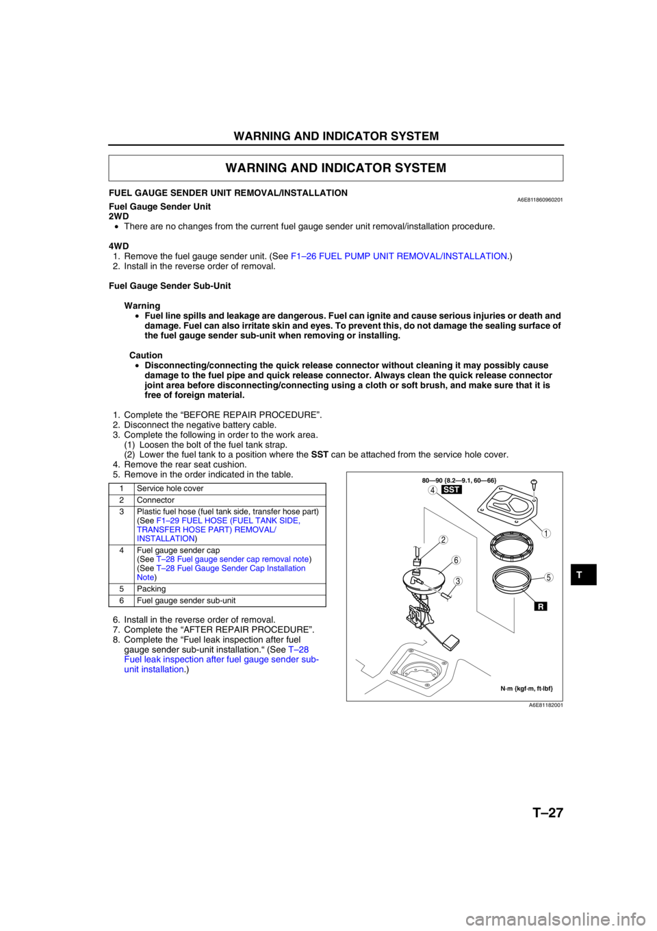
5. Remove in the order indicated in the table.
6. Install in the reverse order of removal.
7. Complete the “AFTER REPAIR PROCEDURE”.
8. Complete the “Fuel leak inspection after fuel
gauge sender sub-unit installation.“ (See T–28
Fuel leak inspection after fuel gauge sender sub-
unit installation.)
WARNING AND INDICATOR SYSTEM
1 Service hole cover
2 Connector
3 Plastic fuel hose (fuel tank side, transfer hose part)
(See F1–29 FUEL HOSE (FUEL TANK SIDE,
TRANSFER HOSE PART) REMOVAL/
INSTALLATION)
4 Fuel gauge sender cap
(See T–28 Fuel gauge sender cap removal note)
(See T–28 Fuel Gauge Sender Cap Installation
Note)
5 Packing
6 Fuel gauge sender sub-unit
3
1
4
5
6
2
80—90 {8.2—9.1, 60—66}
N·m {kgf·m, ft·lbf}
R
SST
A6E81182001
Page 839 of 909

T–28
WARNING AND INDICATOR SYSTEM
Fuel gauge sender cap removal note
1. Using the SST, remove the fuel gauge sender
cap.
Fuel Gauge Sender Cap Installation Note
1. Verify that the fuel tank mark is aligned with the
fuel gauge sender sub-unit mark as shown.
2. Using the SST, tighten the fuel gauge sender cap
without shifting the mark.
Tightening torque
80—90 N·m {8.2—9.1 kgf·m, 60—66 ft·lbf}
Fuel leak inspection after fuel gauge sender sub-unit installation
1. Drive the vehicle.
2. Perform a quick start and a hard brake 5—6 times.
3. Stop the vehicle.
4. Verify that there is no fuel leakage near the fuel pump unit in the vehicle interior.
End Of Sie
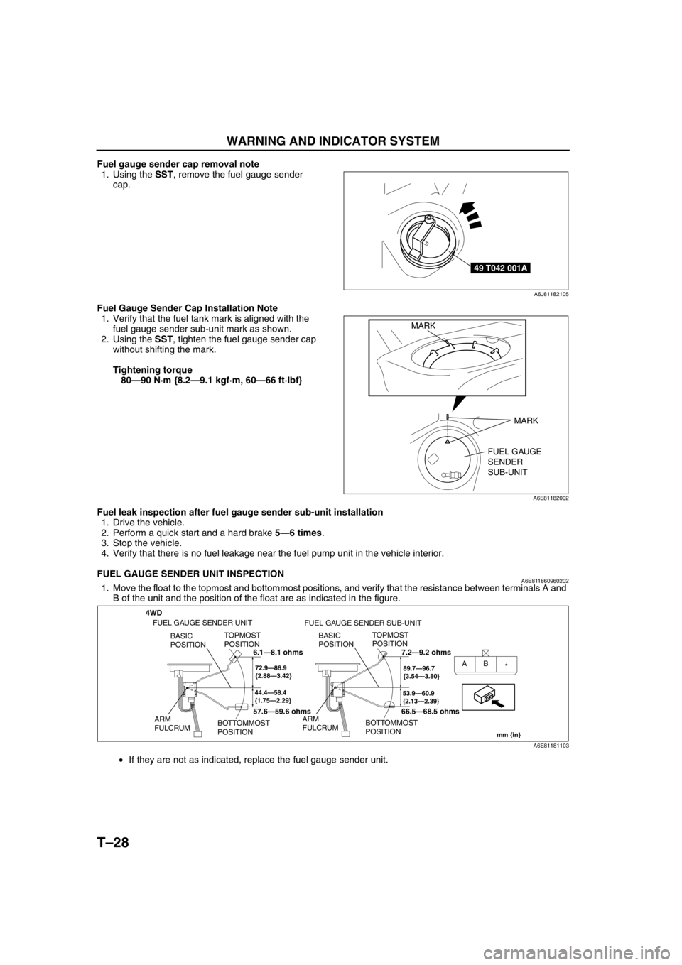
FUEL GAUGE SENDER UNIT INSPECTIONA6E8118609602021. Move the float to the topmost and bottommost positions, and verify that the resistance between terminals A and
B of the unit and the position of the float are as indicated in the figure.
•If they are not as indicated, replace the fuel gauge sender unit.
End Of Sie
49 T042 001A
A6J81182105
FUEL GAUGE
SENDER
SUB-UNIT MARK
MARK
A6E81182002
4WD
44.4—58.4
{1.75—2.29}
TOPMOST
POSITION
BOTTOMMOST
POSITION BASIC
POSITION
ARM
FULCRUM
72.9—86.9
{2.88—3.42}AB
*
53.9—60.9
{2.13—2.39}
TOPMOST
POSITION
BOTTOMMOST
POSITION BASIC
POSITION
ARM
FULCRUM
89.7—96.7
{3.54—3.80}
mm {in}
FUEL GAUGE SENDER UNIT
FUEL GAUGE SENDER SUB-UNIT
6.1—8.1 ohms
57.6—59.6 ohms7.2—9.2 ohms
66.5—68.5 ohms
A6E81181103
Page 840 of 909

THEFT-DETERRENT SYSTEM
T–29
T
INTRUDER SENSOR REMOVAL/INSTALLATIONA6E812000172201Front Intruder Sensor (With Sliding Sunroof)
•There are no changes from the current front intruder sensor removal/installation procedure.
Center Intruder Sensor (Without Sliding Sunroof)
•There are no changes from the current center intruder sensor removal/installation procedure.
Rear Intruder Sensor (WGN)
1. Disconnect the negative battery cable.
2. Remove the headliner.
3. Remove in the order indicated in the table.
4. Install in the reverse order of removal.
End Of Sie
THEFT-DETERRENT SYSTEM
1 Connector
2Screw
3 Rear intruder sensor
1
2
3
A6E81201105