MAZDA 626 1987 Workshop Manual
Manufacturer: MAZDA, Model Year: 1987,
Model line: 626,
Model: MAZDA 626 1987
Pages: 1865, PDF Size: 94.35 MB
MAZDA 626 1987 Workshop Manual
626 1987
MAZDA
MAZDA
https://www.carmanualsonline.info/img/28/57059/w960_57059-0.png
MAZDA 626 1987 Workshop Manual
Trending: remote control, horn, battery replacement, child lock, lights, fuses, fuel tank capacity
Page 1211 of 1865
ASSEMBLY 7C
76G07C-249
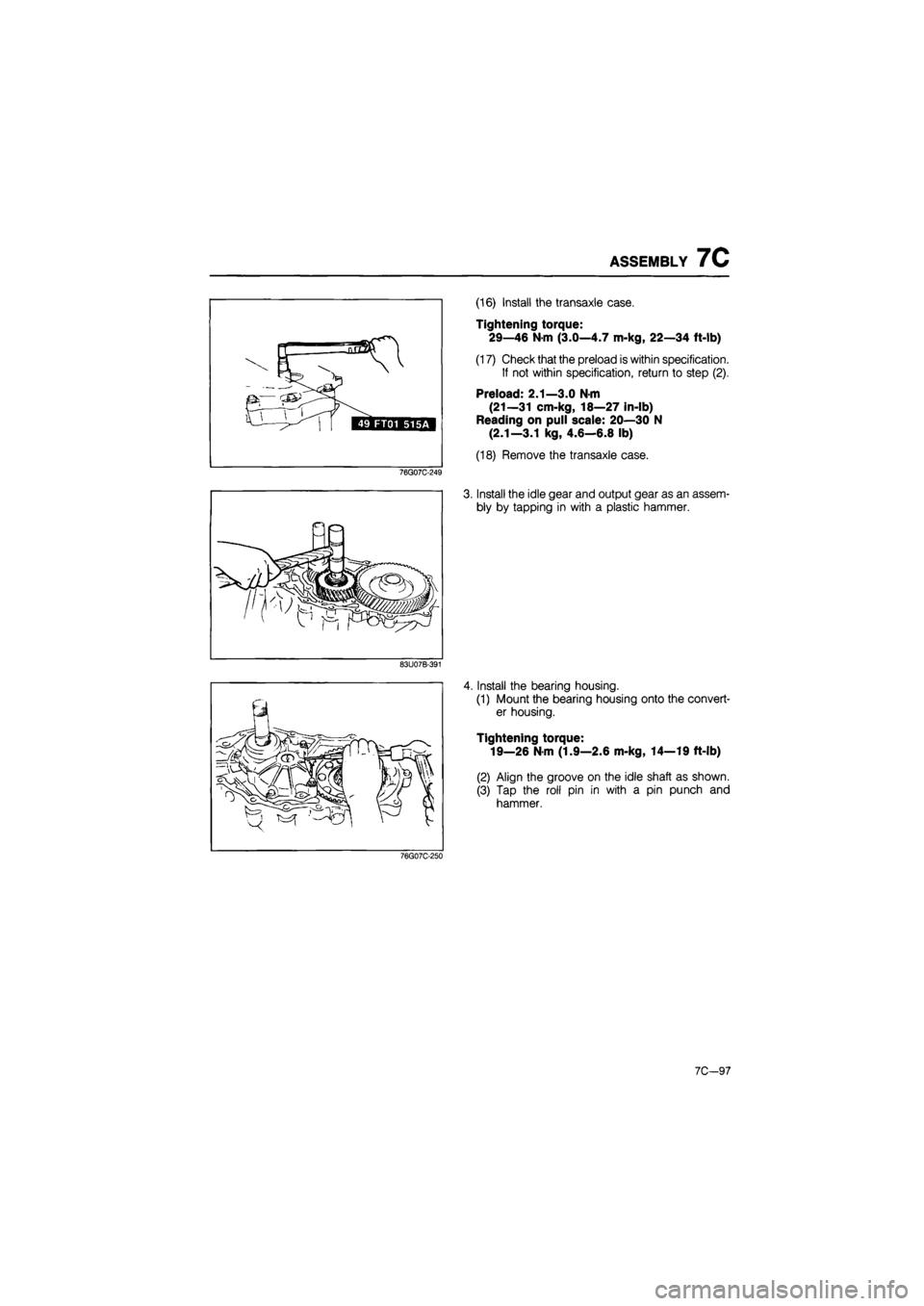
(16) Install the transaxle case.
Tightening torque:
29—46 N-m (3.0—4.7 m-kg, 22—34 ft-lb)
(17) Check that the preload is within specification.
If not within specification, return to step (2).
Preload: 2.1—3.0 N-m
(21—31 cm-kg, 18—27 in-lb)
Reading on pull scale: 20—30 N
(2.1—3.1 kg, 4.6—6.8 lb)
(18) Remove the transaxle case.
3. Install the idle gear and output gear as an assem-
bly by tapping in with a plastic hammer.
83U07B-391
4. Install the bearing housing.
(1) Mount the bearing housing onto the convert-
er housing.
Tightening torque:
19—26 N-m (1.9—2.6 m-kg, 14—19 ft-lb)
(2) Align the groove on the idle shaft as shown.
(3) Tap the roll pin in with a pin punch and
hammer.
76G07C-250
7C-97
Page 1212 of 1865
7C ASSEMBLY
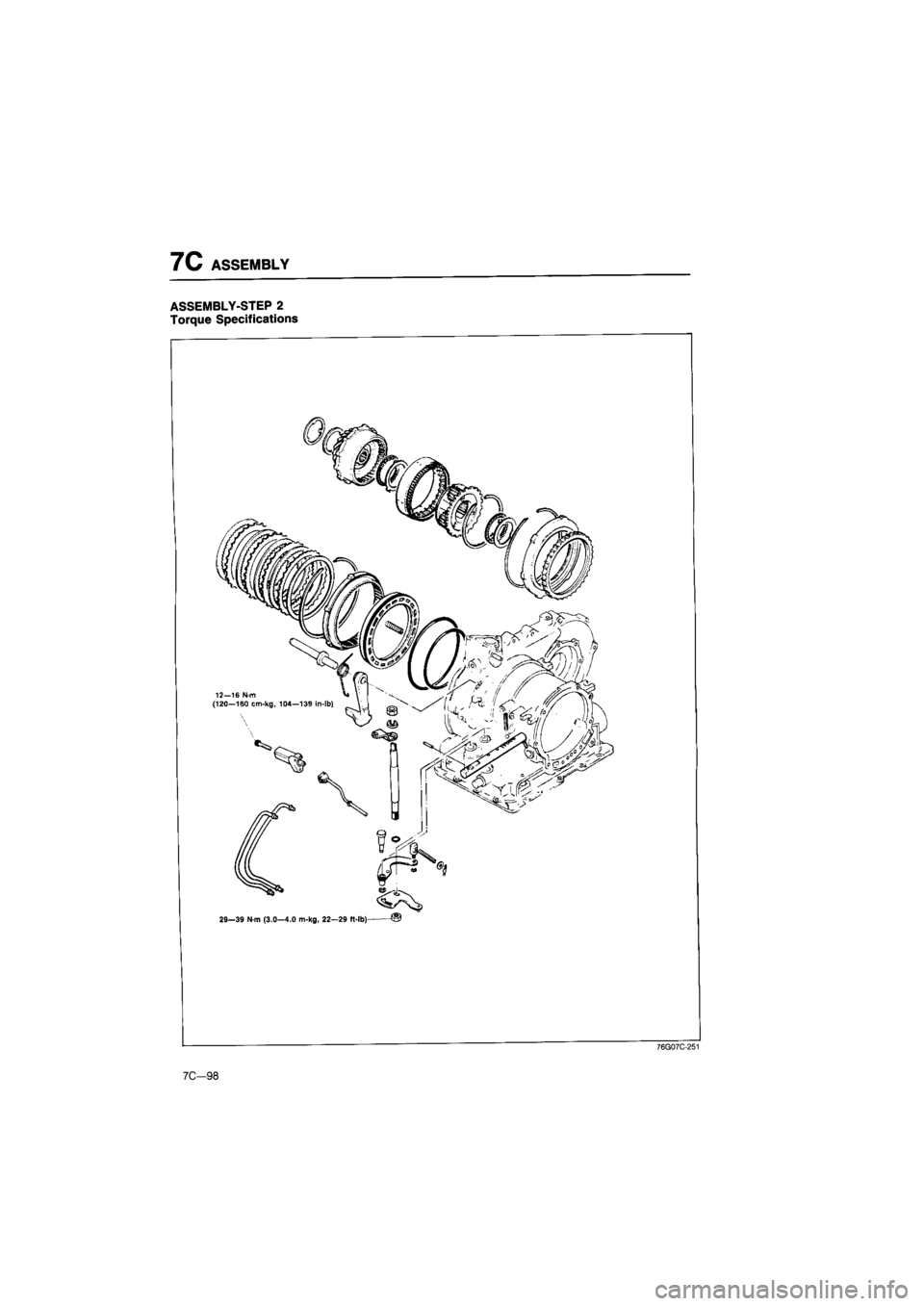
ASSEMBLY-STEP 2
Torque Specifications
29—39 N-m (3.0—4.0 m-kg, 22—29 ft-lb) ©
7C-98
76G07C-251
Page 1213 of 1865
ASSEMBLY 7C
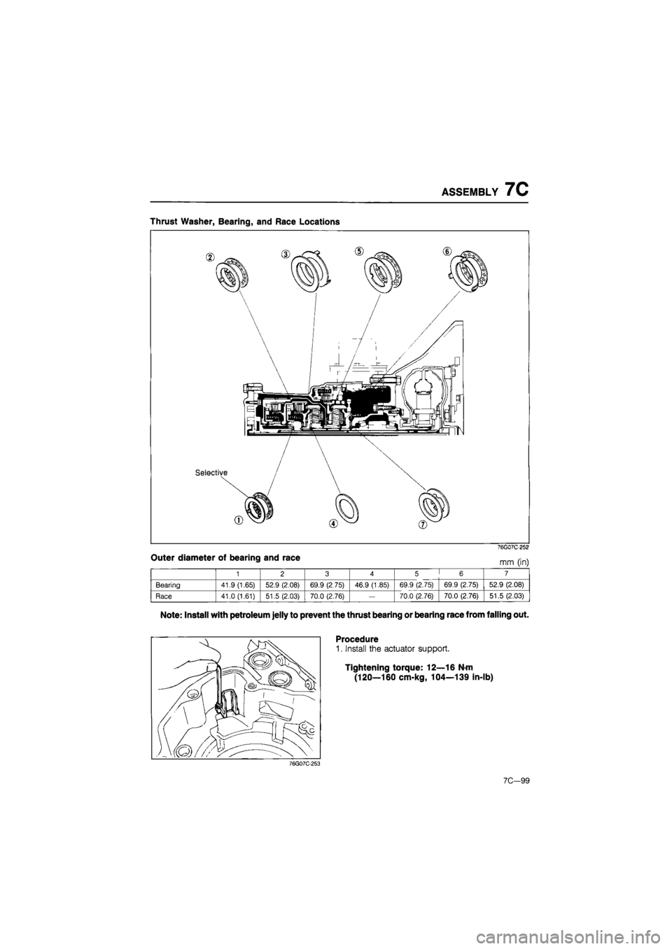
Thrust Washer, Bearing, and Race Locations
Outer diameter of bearing and race
76G07C252
mm (in)
1 2 3 4 5 6 7
Bearing 41.9 (1.65) 52.9 (2.08) 69.9 (2.75) 46.9 (1.85) 69.9 (2.75) 69.9 (2.75) 52.9 (2.08)
Race 41.0 (1.61) 51.5 (2.03) 70.0 (2.76)
—
70.0 (2.76) 70.0 (2.76) 51.5 (2.03)
Note: Install with petroleum jelly to prevent the thrust bearing or bearing race from falling out.
Procedure
1. Install the actuator support.
Tightening torque: 12—16 N-m
(120—160 cm-kg, 104—139 in-lb)
76G07C-253
7C—99
Page 1214 of 1865
7C ASSEMBLY
76G07C-254
76G07C-255
76G07C-256
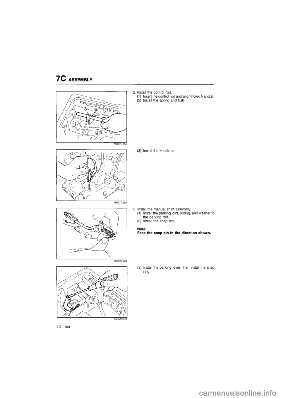
2. Install the control rod.
(1) Insert the control rod and align holes A and B.
(2) Install the spring and ball.
(3) Install the knock pin.
3. Install the manual shaft assembly.
(1) Install the parking joint, spring, and washer to
the parking rod.
(2) Install the snap pin.
Note
Face the snap pin in the direction shown.
(3) Install the parking lever; then install the snap
ring.
76G07C-257
7C—100
Page 1215 of 1865
ASSEMBLY 7C
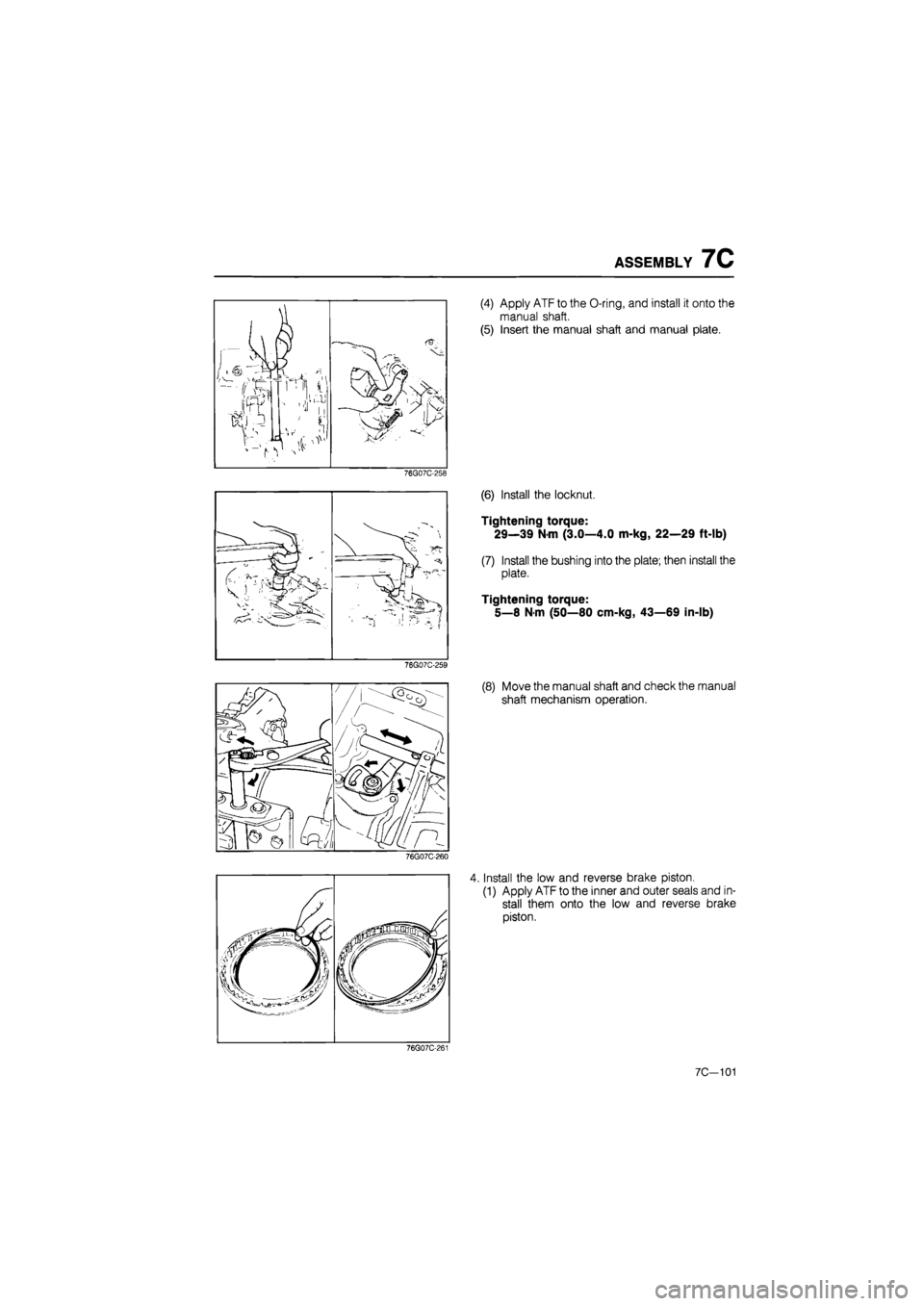
(4) Apply ATF to the O-ring, and install it onto the
manual shaft.
(5) Insert the manual shaft and manual plate.
76G07C-258
(6) Install the locknut.
Tightening torque:
29—39 N-m (3.0—4.0 m-kg, 22—29 ft-lb)
(7) Install the bushing into the plate; then install the
plate.
Tightening torque:
5—8 N-m (50—80 cm-kg, 43—69 in-lb)
76G07C-260
4. Install the low and reverse brake piston.
(1) Apply ATF to the inner and outer seals and in-
stall them onto the low and reverse brake
piston.
76G07C-261
7C-101
Page 1216 of 1865
7C ASSEMBLY
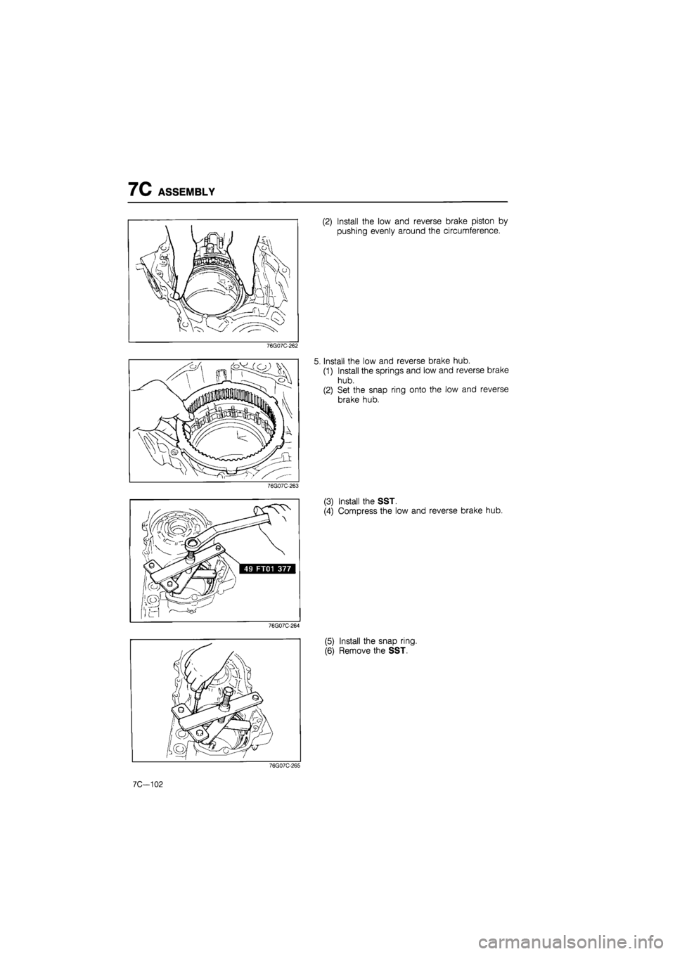
(2) Install the low and reverse brake piston by
pushing evenly around the circumference.
76G07C-262
Install the low and reverse brake hub.
(1) Install the springs and low and reverse brake
hub.
(2) Set the snap ring onto the low and reverse
brake hub.
76G07C-263
(3) Install the SST.
(4) Compress the low and reverse brake hub.
76G07C-264
(5) Install the snap ring.
(6) Remove the SST.
76G07C-265
7C—102
Page 1217 of 1865
ASSEMBLY 7C
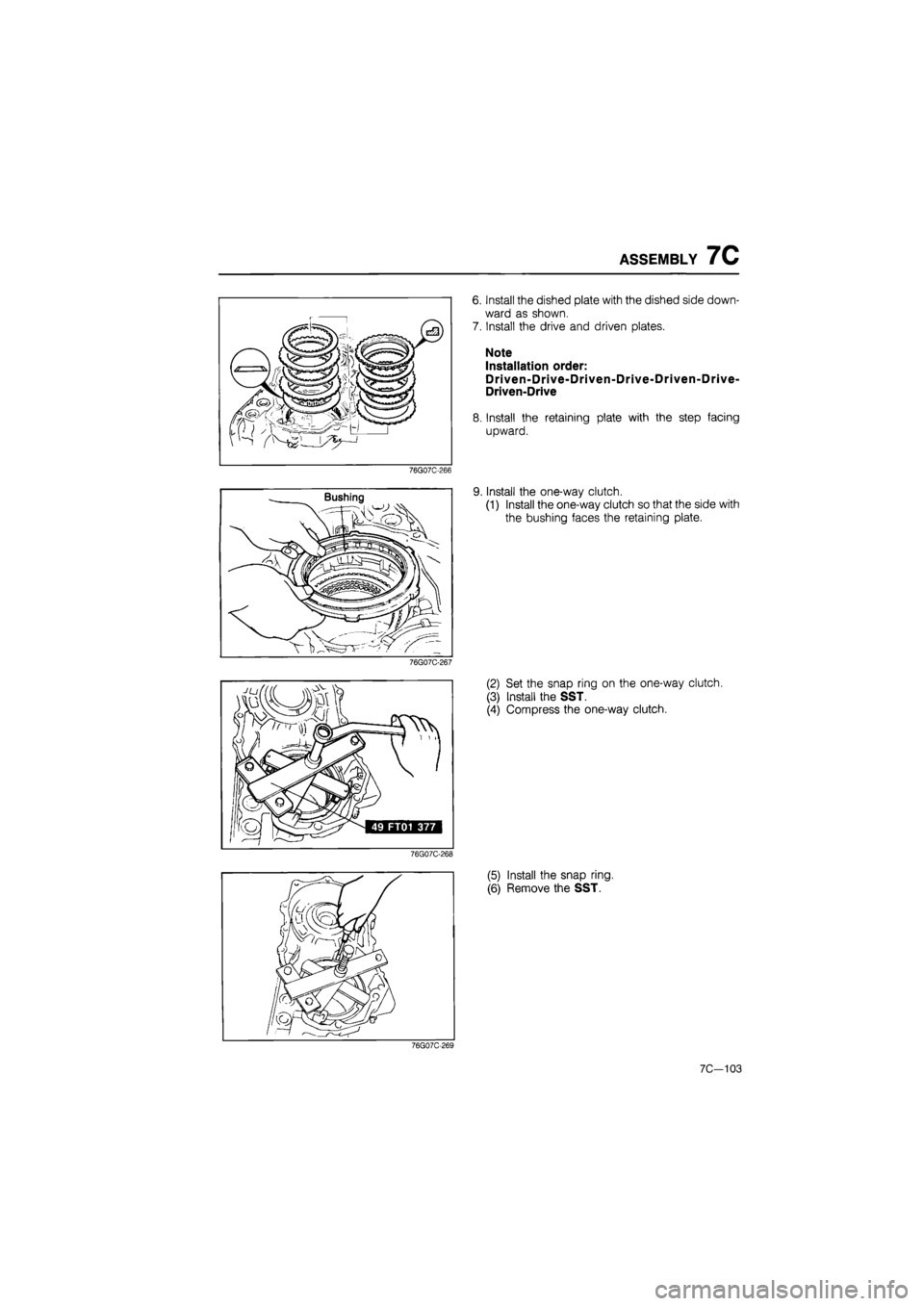
6. Install the dished plate with the dished side down-
ward as shown.
7. Install the drive and driven plates.
Note
Installation order:
Driven-Drive-Driven-Drive-Driven-Drive-
Driven-Drive
8. Install the retaining plate with the step facing
upward.
76G07C-266
9. Install the one-way clutch.
(1) Install the one-way clutch so that the side with
the bushing faces the retaining plate.
76G07C-267
(2) Set the snap ring on the one-way clutch.
(3) Install the SST.
(4) Compress the one-way clutch.
76G07C-268
(5) Install the snap ring.
(6) Remove the SST.
76G07C-269
7C—103
Page 1218 of 1865
7C ASSEMBLY
76G07C-270
76G07C-271
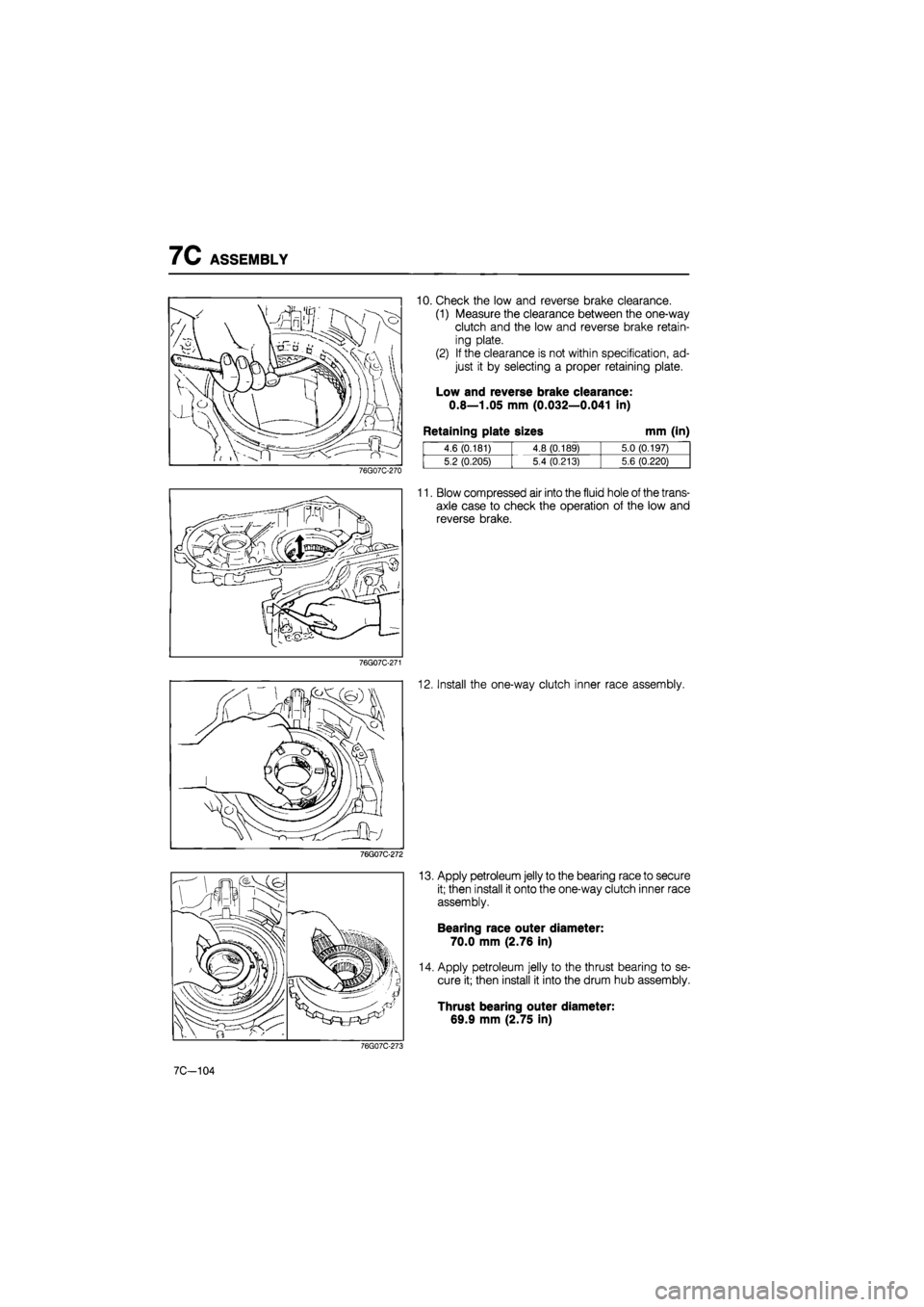
10. Check the low and reverse brake clearance.
(1) Measure the clearance between the one-way
clutch and the low and reverse brake retain-
ing plate.
(2) If the clearance is not within specification, ad-
just it by selecting a proper retaining plate.
Low and reverse brake clearance:
0.8—1.05 mm (0.032—0.041 in)
Retaining plate sizes mm (in)
4.6 (0.181) 4.8 (0.189) 5.0 (0.197)
5.2 (0.205) 5.4 (0.213) 5.6 (0.220)
11. Blow compressed air into the fluid hole of the trans-
axle case to check the operation of the low and
reverse brake.
12. Install the one-way clutch inner race assembly.
76G07C-272
13. Apply petroleum jelly to the bearing race to secure
it; then install it onto the one-way clutch inner race
assembly.
Bearing race outer diameter:
70.0 mm (2.76 in)
14. Apply petroleum jelly to the thrust bearing to se-
cure it; then install it into the drum hub assembly.
Thrust bearing outer diameter:
69.9 mm (2.75 in)
76G07C-273
7C-104
Page 1219 of 1865
ASSEMBLY 7C
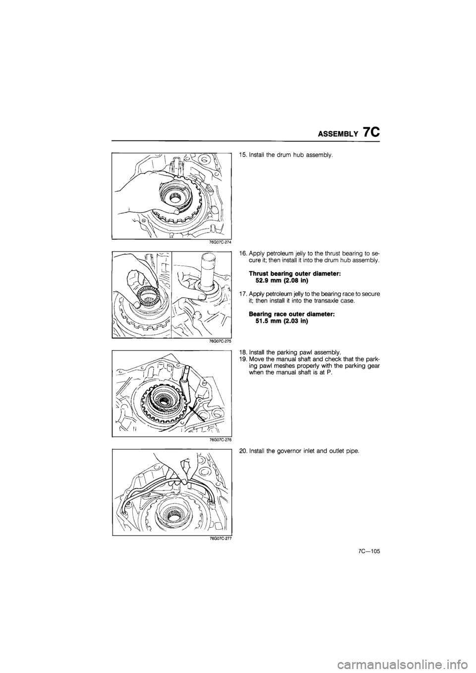
15. Install the drum hub assembly.
76G07C-274
76G07C-275
16. Apply petroleum jelly to the thrust bearing to se-
cure it; then install it into the drum hub assembly.
Thrust bearing outer diameter:
52.9 mm (2.08 in)
17. Apply petroleum jelly to the bearing race to secure
it; then install it into the transaxle case.
Bearing race outer diameter:
51.5 mm (2.03 in)
18. Install the parking pawl assembly.
19. Move the manual shaft and check that the park-
ing pawl meshes properly with the parking gear
when the manual shaft is at P.
76G07C-276
20. Install the governor inlet and outlet pipe.
76G07C-277
7C—105
Page 1220 of 1865
7C ASSEMBLY
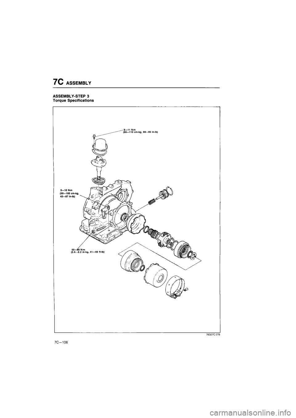
ASSEMBLY-STEP 3
Torque Specifications
76G07C-278
7C-106
Trending: tires, wipers, brake pads, service indicator, radiator cap, stop start, technical specifications
