MAZDA 626 1987 Workshop Manual
Manufacturer: MAZDA, Model Year: 1987, Model line: 626, Model: MAZDA 626 1987Pages: 1865, PDF Size: 94.35 MB
Page 1411 of 1865
MASTER CYLINDER 1 1
76G11X-015
76G11X-016
76G11X-017
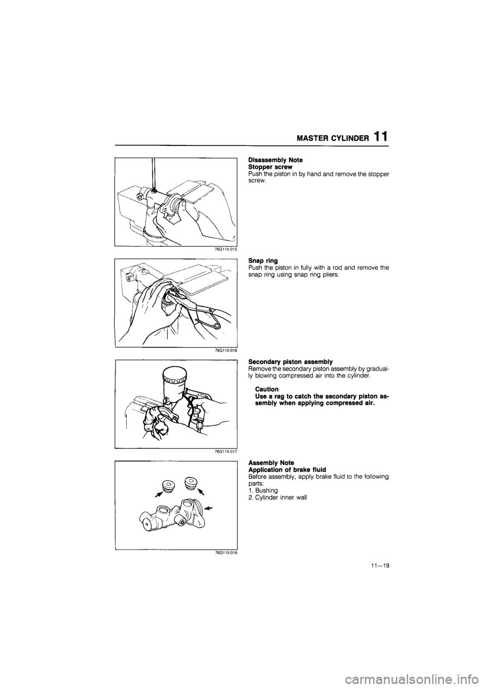
Disassembly Note
Stopper screw
Push the piston in by hand and remove the stopper
screw.
Snap ring
Push the piston in fully with a rod and remove the
snap ring using snap ring pliers.
Secondary piston assembly
Remove the secondary piston assembly by gradual-
ly blowing compressed air into the cylinder.
Caution
Use a rag to catch the secondary piston as-
sembly when applying compressed air.
Assembly Note
Application of brake fluid
Before assembly, apply brake fluid to the following
parts:
1. Bushing
2. Cylinder inner wall
76G11X-018
11—19
Page 1412 of 1865
1 1 MASTER CYLINDER
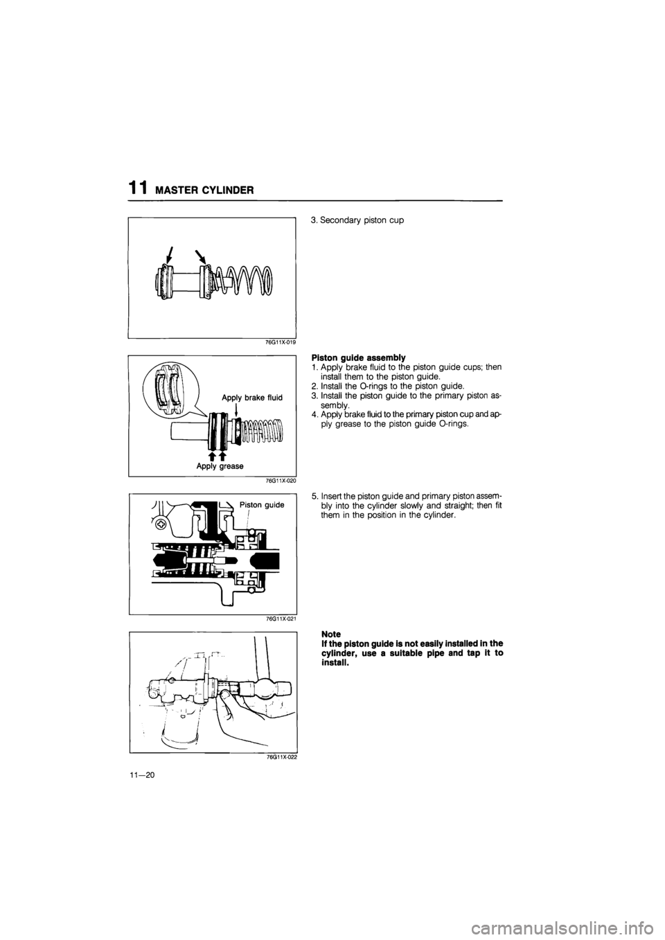
3. Secondary piston cup
76G11X-019
Apply brake fluid
t Apply grease
76G11X-020
Piston guide assembly
1. Apply brake fluid to the piston guide cups; then
install them to the piston guide.
2. Install the O-rings to the piston guide.
3. Install the piston guide to the primary piston as-
sembly.
4. Apply brake fluid to the primary piston cup and ap-
ply grease to the piston guide O-rings.
5. Insert the piston guide and primary piston assem-
bly into the cylinder slowly and straight; then fit
them in the position in the cylinder.
76G11X-021
Note
If the piston guide is not easily installed in the
cylinder, use a suitable pipe and tap it to
install.
76G11X-022
11—20
Page 1413 of 1865
MASTER CYLINDER 1 1
86U11X-031
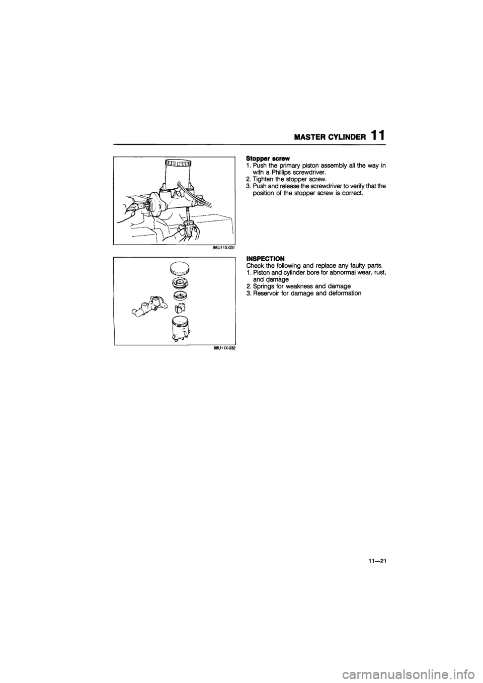
Stopper screw
1. Push the primary piston assembly all the way in
with a Phillips screwdriver.
2. Tighten the stopper screw.
3. Push and release the screwdriver to verify that the
position of the stopper screw is correct.
INSPECTION
Check the following and replace any faulty parts.
1. Piston and cylinder bore for abnormal wear, rust,
and damage
2. Springs for weakness and damage
3. Reservoir for damage and deformation
86U11X-032
11—21
Page 1414 of 1865
1 1 MASTER CYLINDER
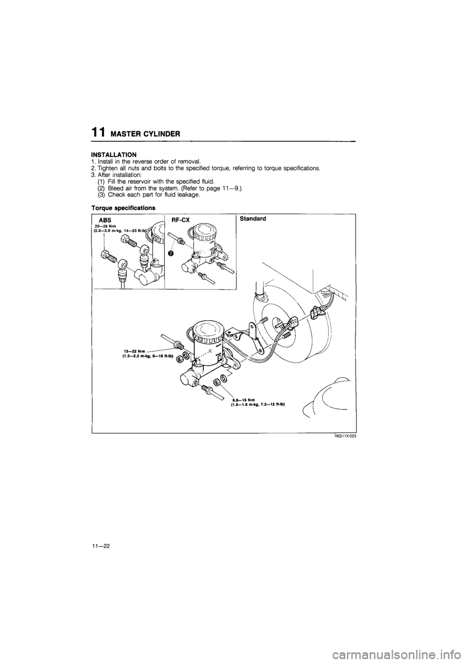
INSTALLATION
1. Install in the reverse order of removal.
2. Tighten all nuts and bolts to the specified torque, referring to torque specifications.
3. After installation:
(1) Fill the reservoir with the specified fluid.
(2) Bleed air from the system. (Refer to page 11—9.)
(3) Check each part for fluid leakage.
Torque specifications
11—22
Page 1415 of 1865

MASTER CYLINDER 1 1
Installation Note
Piston to push rod clearance adjustment
(Except RHD DOHC TURBO)
Before installing the master cylinder, check the clear-
ance between the piston of the master cylinder and
the push rod of the power brake unit as follows.
1. Place the SST on the top of the master cylinder;
then turn the adjust bolt until it contacts the bot-
tom of the push rod hole in the piston.
76G11X-024
2. Apply 500 mmHg (19.7 inHg) vacuum to the pow-
er brake unit with a vacuum pump.
76G11X-100
——x y V \ ''/v'/
\
i By Adjust bolt
86U11X-036
Locknut IV"
\ i i '
3. Invert the SST used in step 1, and place it on the
power brake unit.
4. Check the clearance between the adjust bolt and
the push rod of the power brake unit. If it is not
0 mm, loosen the push rod locknut and turn the
push rod to adjust.
76G11X-101
11-23
Page 1416 of 1865
1 1 MASTER CYLINDER
76G11X-025
II
L
\ Clearance (B)
Clearance (A) , j Adjust nut
•I
76G11X-026
Clearance (B)
49 B043 001
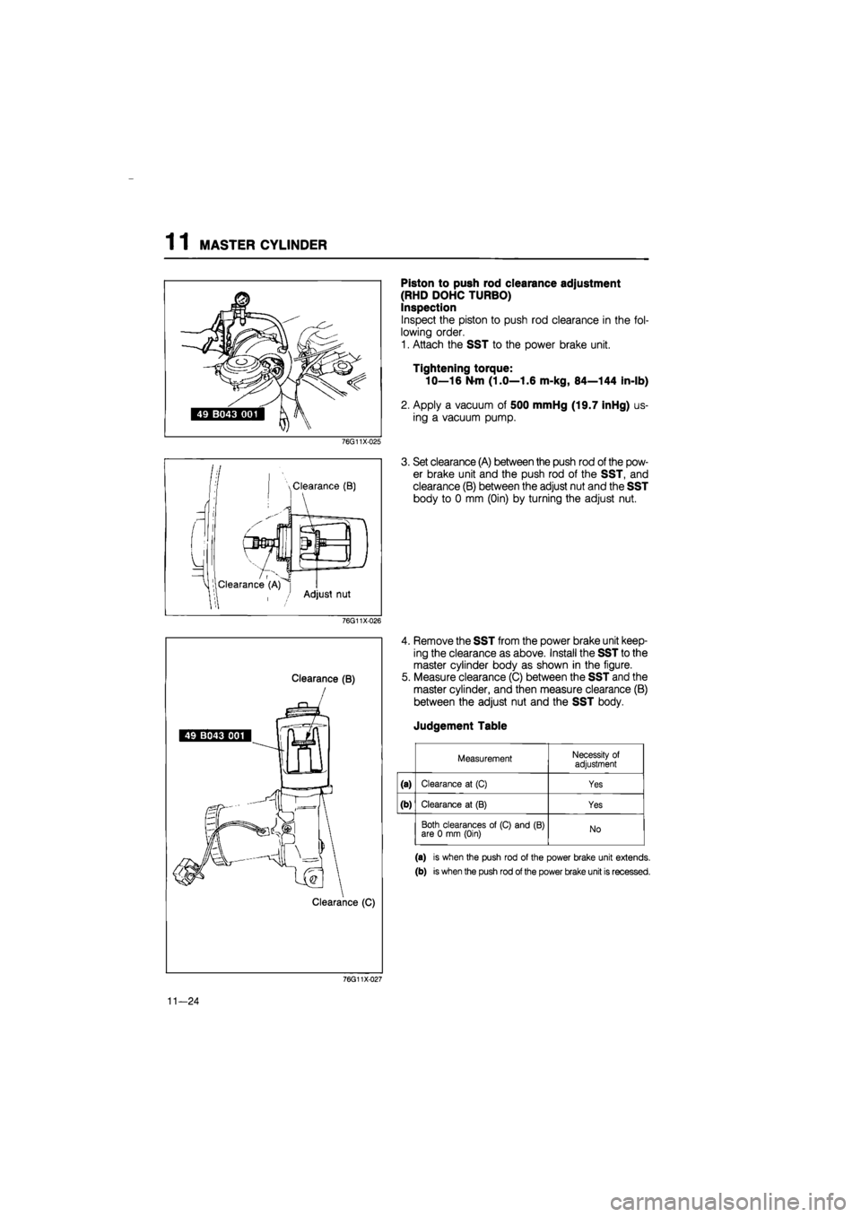
Piston to push rod clearance adjustment
(RHD DOHC TURBO)
Inspection
Inspect the piston to push rod clearance in the fol-
lowing order.
1. Attach the SST to the power brake unit.
Tightening torque:
10—16 N-m (1.0—1.6 m-kg, 84—144 in-lb)
2. Apply a vacuum of 500 mmHg (19.7 inHg) us-
ing a vacuum pump.
3. Set clearance (A) between the push rod of the pow-
er brake unit and the push rod of the SST, and
clearance (B) between the adjust nut and the SST
body to 0 mm (Oin) by turning the adjust nut.
4. Remove the SST from the power brake unit keep-
ing the clearance as above. Install the SST to the
master cylinder body as shown in the figure.
5. Measure clearance (C) between the SST and the
master cylinder, and then measure clearance (B)
between the adjust nut and the SST body.
Judgement Table
Measurement Necessity of adjustment
(a) Clearance at (C) Yes
(b) Clearance at (B) Yes
Both clearances of (C) and (B) are 0 mm (Oin) No
(a) is when the push rod of the power brake unit extends.
(b) is when the push rod of the power brake unit is recessed.
76G11X-027
11-24
Page 1417 of 1865

MASTER CYLINDER 1 1
Adjustment
Adjust the piston to push rod clearance in the follow-
ing order.
1. For (a) of judgement table
(1) Measure the height of (D) and record after
removing the SST from the master cylinder.
76G11X-028
Adjust nut
(2) Install the SST again to the master cylinder,
and turn the adjust nut so that clearance (C)
between the SST and the master cylinder is
0 mm (Oin).
(3) Measure the height of (E) when clearance (C)
is 0 mm (Oin).
(E) — (D) = Projecting amount of the power
brake unit push rod
76G11X-029
(4) Remove the push rod from the power brake
unit.
63G11X-349
(5) Make the piston to push rod clearance 0 mm
(Oin) by turning the push rod and shortening
the push rod length by the amount of (E) — (D).
Note
The threads of the push rod are specially
designed so that the push rod bolt becomes
harder to turn past a certain point to prevent
loosening of the bolt. Turn the push rod bolt
only within this range when adjusting.
76G11X030
11—25
Page 1418 of 1865
1 1 MASTER CYLINDER
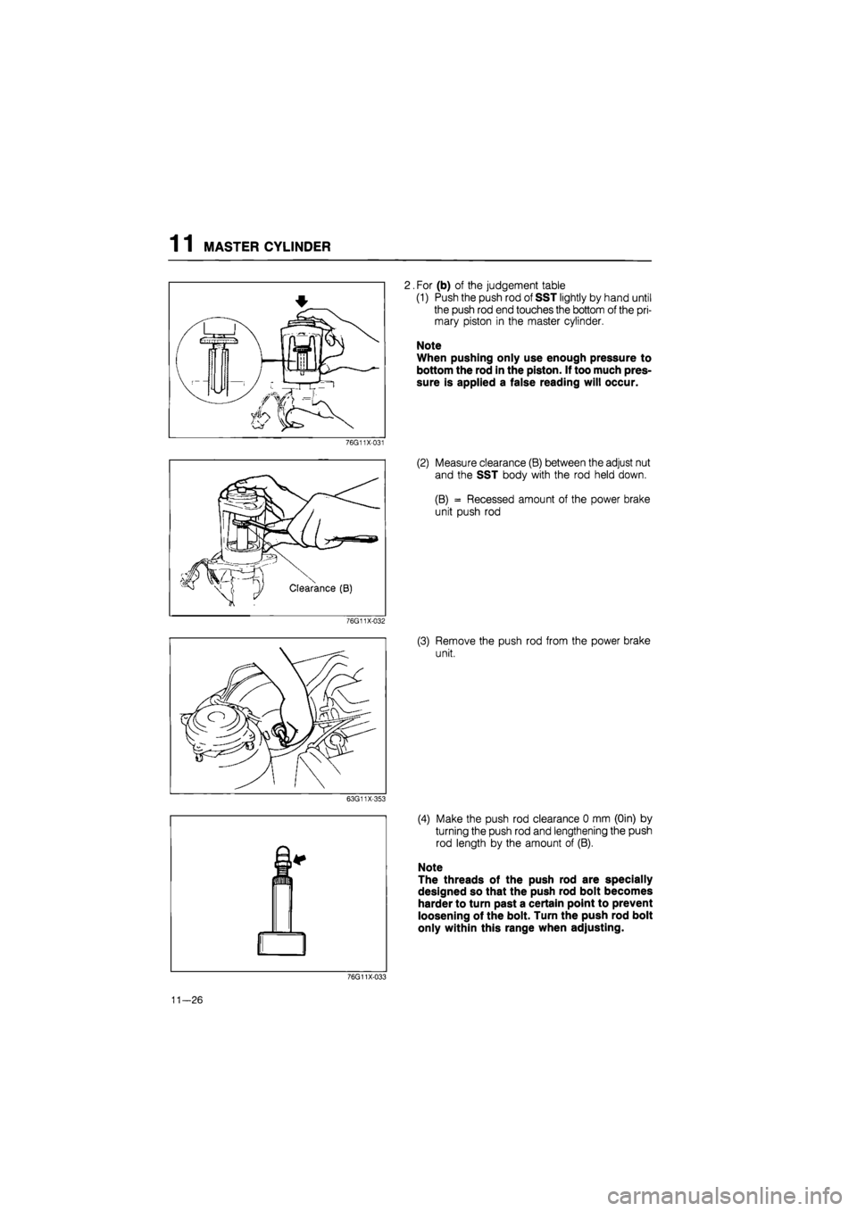
2. For (b) of the judgement table
(1) Push the push rod of SST lightly by hand until
the push rod end touches the bottom of the pri-
mary piston in the master cylinder.
Note
When pushing only use enough pressure to
bottom the rod in the piston. If too much pres-
sure is applied a false reading will occur.
76G11X-031
(2) Measure clearance (B) between the adjust nut
and the SST body with the rod held down.
(B) = Recessed amount of the power brake
unit push rod
76G11X-032
(3) Remove the push rod from the power brake
unit.
63G11X-353
(4) Make the push rod clearance 0 mm (Oin) by
turning the push rod and lengthening the push
rod length by the amount of (B).
Note
The threads of the push rod are specially
designed so that the push rod bolt becomes
harder to turn past a certain point to prevent
loosening of the bolt. Turn the push rod bolt
only within this range when adjusting.
76G11X-033
11—26
Page 1419 of 1865

POWER BRAKE UNIT 1 1
86U11X-038
0
o
X
\ V^ Third
Second
^ First
86U11X-039
O X
fiSy
V
86U11X-040
Pedal-depression Pre!tur!9au9e
force gauge
^Intake manifold
86U11X-041
POWER BRAKE UNIT
FUNCTION CHECK
Simple Method
First step
1. With the engine stopped, depress the pedal a few
times.
2. With the pedal depressed, start the engine
3. If immediately after the engine starts the pedal
moves down slightly, the unit is operating.
Second step
1. Start the engine.
2. Stop the engine after it has run for
1
or 2 minutes.
3. Depress the pedal with the usual force.
4.
If
the first pedal stroke is long and becomes short-
er with subsequent strokes, the unit is operating.
5. If a problem is found, inspect for damage of the
check valve or vacuum hose, and examine the in-
stallation condition. Repair if necessary, and inspect
it once again.
Third step
1. Start the engine.
2. Depress the pedal with the usual force.
3. Stop the engine with the pedal still depressed.
4. Hold the pedal down for about 30 seconds.
5. If the pedal height does not change, the unit is
operating.
6. If there is a problem, check for damage to the
check valve or vacuum hose, and check the con-
nection. Repair if necessary, and check once
again.
If the nature of the problem is still not clear after fol-
lowing the 3 steps above, follow the more detailed
check described in "Method using tester".
Method Using Tester
Connect a pressure gauge, vacuum gauge, and ped-
al depression force gauge as shown in the figure. Af-
ter bleeding the air from the pressure gauge, conduct
the test as described in the 3 steps below.
Note
Use commercially available gauges and ped-
al depression force gauge.
11—27
Page 1420 of 1865

1 1 POWER BRAKE UNIT
a) Checking for vacuum loss
Unloaded condition
1. Start the engine.
2. Stop the engine when the vacuum gauge reading
reaches 500 mmHg (19.7 inHg).
3. Observe the vacuum gauge for 15 seconds.
If
the
gauge shows 475—500 mmHg (18.7—19.7
inHg), the unit is operating.
76G11X-065
Loaded condition
1. Start the engine.
2. Depress the brake pedal with a force of 196 N (20
kg, 44 lb).
3. With the brake pedal depressed, stop the engine
when the vacuum gauge reading reaches 500
mmHg (19.7 inHg).
4. Observe the vacuum gauge for 15 seconds.
If
the
gauge shows 475—500 mmHg (18.7—19.7
inHg), the unit is operating.
76G11X066
b) Checking for hydraulic pressure
1. If with the engine stopped (when vacuum is 0
mmHg) the relation between pedal force and fluid
pressure is within specification, the unit is operating.
Pedal force Fluid pressure
196 N (20 kg, 44 lb) | 1,177 kPa (12 kg/cm2, 171 psi) mia
76G11X-067
2. Start the engine. Depress the brake pedal when
the vacuum reaches 500 mmHg (19.7 inHg).
If the relation between pedal force and fluid pres-
sure is within specification, the unit is operating.
Pedal force Fluid pressure
196 N (20 kg, 44 lb) 7,063 kPa (72 kg/cm2, 1,024 psi) min.
76G11X068
11-28