check engine MAZDA 626 1987 Workshop Manual
[x] Cancel search | Manufacturer: MAZDA, Model Year: 1987, Model line: 626, Model: MAZDA 626 1987Pages: 1865, PDF Size: 94.35 MB
Page 586 of 1865

SWITCH MONITOR FUNCTION 4C
SWITCH MONITOR FUNCTION
Individual switches can be monitored by the SST (Self-Diagnosis checker 49 G018 9A0 or Digital
code checker 49 9200 180).
Note
The test connector must be grounded and the ignition switch ON (engine stopped).
Engine control unit
76G04C-035
Switch Self-Diagnosis Checker (Monitor lamp) Remark Switch Light ON Light OFF Remark
Clutch switch Pedal released Pedal depressed In gear
Neutral switch In gear Neutral Clutch pedal released
Idle switch Pedal depressed Pedal released —
Headlight switch ON OFF —
Rear defroster switch ON OFF —
Blower switch ON OFF Blower motor position: "3" or "4"
Water thermo switch (Elec-trical fan) Terminal disconnected Terminal connected While fan not operating
4C—25
Page 587 of 1865

4C SWITCH MONITOR FUNCTION
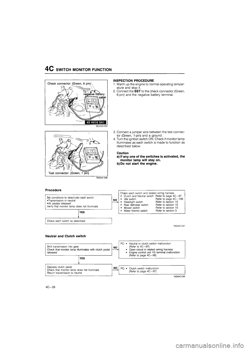
Check connector: (Green, 6 pin)'
N negative battery
ii cable
49 H018 9A1
INSPECTION PROCEDURE
1. Warm up the engine to normal operating temper-
ature and stop it.
2. Connect the SST to the check connector (Green,
6-pin) and the negative battery terminal.
86U04A-034
Test connector: (Green, 1 pin)
3. Connect a jumper wire between the test connec-
tor (Green, 1-pin) and a ground.
4. Turn the ignition switch ON. Check if monitor lamp
illuminates as each switch is made to function as
described below.
Caution
a) If any one of the switches is activated, the
monitor lamp will stay on.
b)Do not start the engine.
76G04C-036
76G04C-037
Neutral and Clutch switch
4C—26
Page 590 of 1865

IDLE ADJUSTMENT 4C
Idle speed
Automatic
Control
Function
Engine Control Unit
IDLE
ADJUSTMENT
IDLE SPEED
The idle speed is controlled automatically by the
engine control unit through the idle speed con-
trol (ISC) solenoid valve, it is not necessary to
adjust the idle speed.
However, if the idle speed is not within specifi-
cation, the idle speed must be adjusted.
76G04C-044
Preparation
1) Check the condition of the engine (plugs, leaks in
hoses, etc.).
2) Make sure all accessories are OFF.
3) Warm up the engine and run it for three minutes
at 2,500—3,000 rpm in neutral.
4) Check the initial ignition timing and adjust it if
necessary.
76G04C-045
Inspection
1. Check that the idle speed is within specification
without grounding the test connector (Green,
1-pin).
Specification:
Applied load Idle speed
No load 750 ± 50 rpm
P/S load 750 ± 50 rpm
A/C and/or E/L load 800 ± 50 rpm
76G04C-046 2. If not correct, adjust the initial idle speed.
Adjustment
1. Ground the test connector (Green, 1-pin) with a
jumper wire.
2. Turn all accessories and loads OFF.
76G04C-047
4C—29
Page 591 of 1865

4C IDLE ADJUSTMENT
76G04C-048
Idle speed
Automatic
Control
Function
Engine Control Unit
76G04C-049
76G04C-050
3. Remove the blind cap and adjust the initial idle
speed to specification by turning the air adjust
screw.
Initial idle speed: 750 ± 50 rpm
4. After adjusting the idle speed, install the blind cap
and disconnect the jumper wire from the test con-
nector.
5. Recheck the idle speed.
6. If not within specification, check the idle speed con-
trol (ISC) system.
IDLE MIXTURE (Unleaded Fuel)
An automatic compensation function for air/fuel
mixture is built into the engine control unit, it
is not necessary to check and adjust the idle
mixture.
IDLE MIXTURE (Leaded Fuel)
Note
Before checking or adjusting the idle mixture,
check and adjust the idle speed, if necessary.
1. Insert a gas analyzer pick-up into the tail pipe.
2. Check that the CO and HC concentrations are with-
in specification.
CO concentration: 1.5 ± 0.5%
HC concentration: Less than 1,000 PPM
3. If the CO or HC concentration is not within specifi-
cation, turn the adjust screw
with
the SST to adjust.
76G04C-051
4C-30
Page 594 of 1865

INTAKE AIR SYSTEM 4C
76G04C-054
76G04C-055
76G04C-056
Removal Note
Water hose
Before disconnecting the water hose, drain two liters
of engine coolant.
Delivery pipe assembly.
1. Separate the fuel return pipe from the delivery pipe
assembly.
2. Remove the delivery pipe assembly and the fuel
return pipe.
PARTS INSPECTION
Air Cleaner Element
1. Check the condition of the air cleaner element.
2. Blow out the dust with compressed air, if
necessary.
Caution
a) The air cleaner must be replaced at the in-
tervals outlined in the maintenance
schedule.
b) Never drive the vehicle without the air
cleaner element, otherwise, damage to the
air flow sensor (hot wire) will occur.
c) Never use an oil permeated air cleaner ele-
ment, otherwise, contamination of the hot
wire will occur.
4C—33
Page 599 of 1865

4C INTAKE AIR SYSTEM
Installation Note
Water hose spring clamps
Face the clamp end as shown in the figure.
Gasket
Use new gaskets at the intake manifold, dynamic
chamber, and throttle body.
86U04A-056
• . v 1
Engine 1 Ml' ' •-
hanger ^ •
• i::£?^Solenoid valve bracket
Air cleaner. r^I. ^jUvW;
Th V
Ground harnesses
Make sure that the ground harnesses are tightened
securely at the following positions.
(1) Air cleaner upper case
(2) Solenoid valve braket
(3) Engine hanger
76G04C-062
Solenoid valve connectors
Connect the solenoid valve connectors at the posi-
tions shown in the figure.
76G04C-063
Inspection after installation
1. After completing installation, fill up the engine with
the specified engine coolant.
2. Warm up the engine and run it at idle.
3. Check for any vacuum, coolant, or fuel leaks.
76G04C-064
4C-38
Page 600 of 1865

VIC SYSTEM 4C
VARIABLE INERTIA CONTROL
(VIC)
SYSTEM
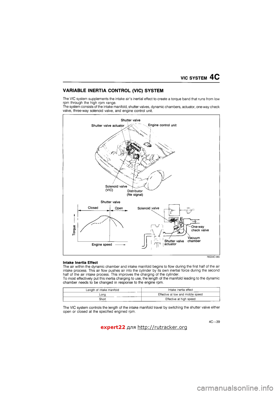
The VIC system supplements the intake air's inertial effect to create a torque band that runs from low
rpm through the high rpm range.
The system consists of the intake manifold, shutter valves, dynamic chambers, actuator, one-way check
valve, three-way solenoid valve, and engine control unit.
Shutter valve
Shutter valve
76G04C-065
Intake Inertia Effect
The air within the dynamic chamber and intake manifold begins to flow during the first half of the air
intake process. This air flow pushes air into the cylinder by its own inertial force during the second
half of the air intake process. This improves the charging of the cylinder.
To most effectively put this inertia charging to use, the length of the manifold leading to the dynamic
chamber needs to be changed in response to the engine rpm.
Length of intake manifold Intake inertia effect
Long Effective at low and middle speed
Short Effective at high speed
The VIC system controls the length of the intake manifold travel by switching the shutter valve either
open or closed at the specified engined rpm.
expert22 fl/i* http://rutracker.org
4C—39
Page 601 of 1865

7C VIC SYSTEM
COMPONENT DESCRIPTION
Component Function Remark
Dynamic chamber Provides chamber for VIC system operation Integrates one-way check valve
Engine control unit Monitors engine rpm, controls solenoid valve Unleaded fuel: ON at above 5200 rpm Leaded fuel: ON at above 5400 rpm
Intake manifold Provides short and long length of intake travel Integrates shutter valve
One-way check valve Holds vacuum in vacuum chamber Installed between dynamic chamber and vacuum chamber
Ne signal pick-up Detects crank angle at 180° intervals; sends signal to control unit Installed in distributor
Solenoid valve (Vlfc) Controls vacuum to shutter valve actuator
Shutter valve Closes short intake port
Shutter valve actuator Actuates shutter valve according to
vacuum from solenoid valve
76G04C-066
TROUBLESHOOTING
Check the condition of the wiring harness and connectors before checking the sensor or switches.
Note
Make the system inspection first. If no problem is found, continue with inspection of the
next system of the Troubleshooting Guide. (Refer to pages 4C—10 and 11.)
Possible cause
\Page\.
Symptom
Vacuum chamber (Vacuum leak)
Shutter valve actuator
One-way check valve
Solenoid valve (VIC) Engine control unit (1C)
System
Inspection
Possible cause
\Page\.
Symptom
Vacuum chamber (Vacuum leak)
Shutter valve actuator
One-way check valve Vacuum ' Electric signal | signal
Engine control unit (1C)
System
Inspection
Possible cause
\Page\.
Symptom 4C—42 4C—41 4C—43 4C—42 4C-98 4C—41
Rough idle
During warm up 2 3 4 — — — 1 Rough idle After warming up 2 3 4 — — — 1
Poor acceleration, hesitation,
or lack of power 6 5 7 2 3 4 1
Poor fuel consumption 6 5 7 2 3 4 1
76G04C-067
4C—40
Page 602 of 1865

VIC SYSTEM 4C
System Inspection
1. Warm up the engine to normal operating temper-
ature and run it at idle.
2. Check that the rod has been pulled into the ac-
tuator.
76G04C-068
3. Increase the engine speed and check that the rod
is released above specification.
Specification:
Approx. 5,200 rpm....Unleaded fuel
Approx. 5,400 rpm....Leaded fuel
76G04C-069
Shutter Valve Actuator
1. Disconnect the vacuum hose from the actuator,
and connect a vacuum pump to the actuator.
2. Apply approx. 200 mmHg (7.9 inHg) vacuum
and check that the rod is pulled into the actuator.
76G04C-070
VIC Solenoid Valve
1. Disconnect the vacuum hoses from the solenoid
valve.
2. Blow through the valve from port A and check that
air flows from port B.
76G04C-071
4C—41
Page 603 of 1865

4C VIC SYSTEM
3. Disconnect the solenoid valve connector and con-
nect 12V and a ground to the terminals of the sole-
noid valve.
4. Blow through the valve from port A and check that
air flows from the air filter.
76G04C-072
Electrical Signal
1. Connect a voltmeter to the VIC solenoid valve (O
wire).
2. Increase the engine speed and note the voltmeter
reading.
Voltmeter reading Unleaded fuel Leaded fuel
Approx. 12V Below 5,200 rpm Below 5,400 rpm
Below 2.0V Approx. 5,100 rpm Approx. 5,300 rpm
76G04C-073
Vacuum Signal
1. Disconnect the vacuum hose from the actuator.
2. Place a finger over the port opening and check
that air is pulled in at idle.
3. Increase the engine speed above specification and
check that air is not pulled in.
Specification:
Approx. 5,200 rpm Unleaded fuel
Approx. 5,400 rpm Leaded fuel
4. Connect the vacuum hose.
76G04C-074
76G04C-075
4C-42
Vacuum Chamber
1. Disconnect vacuum hose A from the dynamic
chamber.
2. Connect the vacuum pump to the dynamic
chamber.
3. Apply vacuum and check that it is held.
4. If not correct, check the one-way check valve for
vacuum leakage. (Refer to page 4C—43.)
Note
10 mm Hg (0.39 inHg) drop per 30 seconds is
allowable.
5. If the one-way check valve is good, check the dy-
namic chamber.