MAZDA 626 1987 Workshop Manual
Manufacturer: MAZDA, Model Year: 1987,
Model line: 626,
Model: MAZDA 626 1987
Pages: 1865, PDF Size: 94.35 MB
MAZDA 626 1987 Workshop Manual
626 1987
MAZDA
MAZDA
https://www.carmanualsonline.info/img/28/57059/w960_57059-0.png
MAZDA 626 1987 Workshop Manual
Trending: tyre pressure, jump cable, fuse box diagram, tire pressure, service schedule, fuse chart, air filter
Page 951 of 1865
REMOVAL 7B
12. Remove the front wheels.
13. Remove the splash shields.
14. Drain the ATF.
15. Disconnect the oil cooler outlet and inlet hoses.
76G07B-111
16. Disconnect the tie-rod ends with the SST.
76G07B-112
17. Remove the stabilizer bar control links.
18. Remove the bolts and nuts at the left and right low-
er arm ball joints.
19. Pull the lower arms downward to separate them
from the knuckles.
Caution
Do not damage the ball joint dust boots.
76G07B-113
20. Separate the left driveshaft from the transaxle by
prying with a bar inserted between the shaft and
the case.
Caution
Do not damage the oil seal.
21. Remove the joint shaft bracket.
22. Separate the right driveshaft together with the joint
shaft in the same manner.
76G07B-114
7B—85
Page 952 of 1865
7B REMOVAL
76G07B-115
o ' ...
Exhaust pipe
hanger..
Gasset plate —
76G07B-116
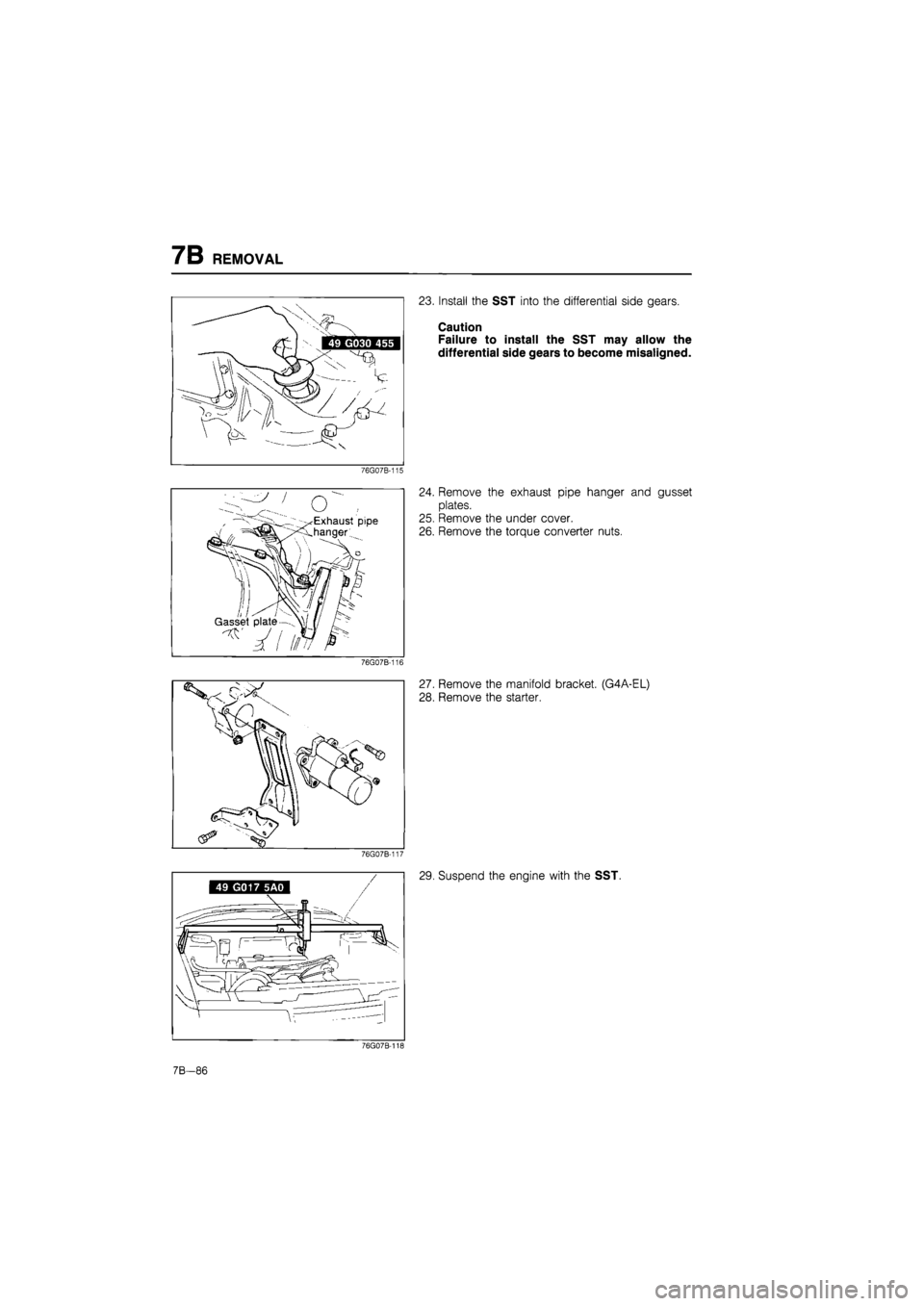
23. Install the SST into the differential side gears.
Caution
Failure to install the SST may allow the
differential side gears to become misaligned.
24. Remove the exhaust pipe hanger and gusset
plates.
25. Remove the under cover.
26. Remove the torque converter nuts.
27. Remove the manifold bracket. (G4A-EL)
28. Remove the starter.
76G07B-117
49 G017 5A0
29. Suspend the engine with the SST.
76G07B-118
7B-86
Page 953 of 1865
REMOVAL 7B
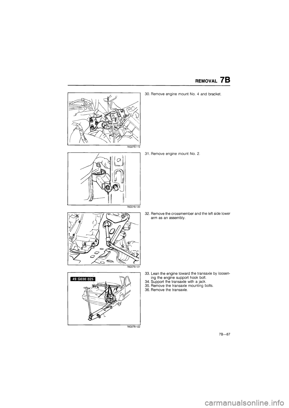
30. Remove engine mount No. 4 and bracket.
76G07B-119
76G07B-120
76G07B-121
31. Remove engine mount No. 2.
32. Remove the crossmember and the left side lower
arm as an assembly.
33. Lean the engine toward the transaxle by loosen-
ing the engine support hook bolt.
34. Support the transaxle with a jack.
35. Remove the transaxle mounting bolts.
36. Remove the transaxle.
76G07B-122
7B—87
Page 954 of 1865
7B DISASSEMBLY
DISASSEMBLY
DISASSEMBLY-STEP 1
Components
1. Torque converter
2. Oil pump shaft
3. Oil level gauge and oil filler tube
4. Pulse generator, fluid temperature switch,
and inhibitor switch
5. Solenoid connector
6. Wire harnesses
7. Harness clip
86U07B-116
8. Oil pipes, oil hoses, and switch box
9. Oil pan and gasket
10. Oil strainer and O-ring
11. Control valve body cover and gasket
12. Throttle cable
13. Solenoid connector (Valve body side)
14. Control valve body
15. Oil pump and gasket
7B-88
Page 955 of 1865
DISASSEMBLY 7B
Procedure
Precaution
(1) Drain the ATF before removing the transaxle from the vehicle.
(2) Disassemble the transaxle in a clean area (dustproof workspace) to prevent dust entry into the
mechanisms.
(3) Clean the transaxle exterior thoroughly with steam and/or cleaning solvents prior to disassembly.
(4) Inspect the individual transaxle components in accordance with the Troubleshooting during disas-
sembly.
(5) Use plastic hammers when applying force to separate the light alloy case joints.
(6) Do not use rags during disassembly.
(7) Neatly arrange the removed parts in order during disassembly.
86U07B-117
7B—89
Page 956 of 1865
7B DISASSEMBLY
4. Assemble the SST.
86U07B-121
5. Lift the transaxle and mount it on the SST.
86U07B-122
Note
Attach the suitable hanger to the oil pump as
shown.
86U07B-123
Warning
Avoid leaning the transaxle to one side dur-
ing disassembly, it may turn quickly and cause
injury.
76U07B-453
7B-90
Page 957 of 1865
DISASSEMBLY 7B
6 G4A-EL
Remove the pulse generator, fluid temperature
switch, and inhibitor switch.
G4A-HL
Remove the inhibitor switch.
76GQ7B-123
7. Disconnect the solenoid connector.
8. Remove the harnesses.
76G07B-124
9. G4A-EL
Remove the harness clip, then remove the oil
pipes, oil hoses and switch box as an assembly.
Note
Remove the ball from the case.
76G07B-125
G4A-HL
Remove the oil pipe.
Note Remove the ball from the case.
76G07B-126
7B—91
Page 958 of 1865
7B DISASSEMBLY
10. Remove the oil pan and gasket.
86U07B-128
86U07B-129
11. Remove the oil strainer and O-ring.
12. Remove the control valve body cover and gasket.
86U07B-130
13. Remove the throttle cable.
(1) Remove the throttle cable attaching bolt and
bracket.
(2) Remove the cable from the throttle cam of the
valve body.
86U07B-131
7B-92
Page 959 of 1865
DISASSEMBLY 7B
14. Pinch the teeth of the solenoid connector and re-
move it by pushing inward.
86U07B-132
15. Remove the control valve body as an assembly.
86U07B-133
16. Remove the oil pump as an assembly.
86U07B-134
7B—93
Page 960 of 1865
7B DISASSEMBLY
DISASSEMBLY-STEP 2
Components
1. Piston stem
2. Snap ring
3. Clutch assembly
4. 2-4 brake band
5. Small sun gear and one-way clutch
6. Anchor strut and shaft
7. Servo
8. One-way clutch and carrier hub assembly
86U07B-135
—Low and reverse brake—
9. Retaining plate
10. Drive and driven plates
11. Internal gear
12. O-ring
13. 3-4 clutch assembly
14. Turbine shaft
7B—94
Trending: wheel bolts, trunk, tire pressure reset, coolant capacity, wheel, roof rack, key battery


