MAZDA MX-5 1994 Owners Manual
Manufacturer: MAZDA, Model Year: 1994, Model line: MX-5, Model: MAZDA MX-5 1994Pages: 1708, PDF Size: 82.34 MB
Page 91 of 1708

INSPECTION / REPAIR 4. Measure the cylinder bores in X and Y directions at three levels (A, B, and C) in each cylinder as shown. Cylinder bore mm(in) I Bore size Diameter 1 1 0.50 (0.020) oversize 1 83.50683.513 (3.2877-3.2879) 1 Standard 0.25 {0.010} oversize 5. Base the boring diameter on the diameter of an oversize piston. All cylinders must be the same diameter. (1) If the cylinder bore exceeds the maximum, rebore the cylinder to oversize. (2) If the difference between measurements A and C ex- ceeds the maximum taper, rebore the cylinder to oversize. 83.000--83.019 (3.2678-3.26841 83.25683.263 (3.2778-3.2780) Taper: 0.019mm (0.0007 in) max. (3) If the difference between measurements X and Y ex- ceeds the maximum out-of-round, rebore the cylin- der to oversize. Out-of-round: 0.019mm (0.0007 in) max. 6. If the upper part of a cylinder wall shows uneven wear, remove the ridge with a ridge reamer. OIL JET 1. Push the check ball and verify that it moves smoothly. 2. Blow through the oil jet and verify that air flows. Gartner Banana
Page 92 of 1708

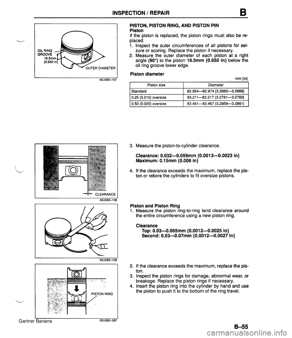
INSPECTION 1 REPAIR ER DIAMETER PISTON, PISTON RING, AND PISTON PIN Piston If the piston is replaced, the piston rings must also be re- placed. 1. lnspect the outer circumferences of all pistons for sei- zure or scoring. Replace the piston if necessary. 2. Measure the outer diameter of each piston at a right angle (90") to the piston 16.5mm (0.650 in} below the oil ring groove lower edge. I Piston diameter ~SUOBX-107 rnrn {in) I Piston size I Diameter I -dk CLEARANCE 1 Standard 1 82.954--82.974 13.2660-3.2666) 1 3. Measure the piston-to-cylinder clearance. Clearance: 0.032--0.059mm (0.0013--0.0023 in) Maximum: 0.15mm (0.006 in) 4. If the clearance exceeds the maximum, replace the pis- ton or rebore the cylinders to fit oversize pistons. 0.25 (0.01 01 oversize 0.50 (0.020) oversize Piston and Piston Ring 1. Measure the piston ring-to-ring land clearance around the entire circumference using a new piston ring. 83.21 1-83.21 7 (3.2761-3.2762) 83.461-83.467 (3.2859-3.2861) Clearance Top: 0.03-0.065mm (0.001 2-0.0025 in) Second: 0.03--0.07mm (0.001 2-4.0027 in) 2. If the clearance exceeds the maximum, replace the pis- ton. 3. lnspect the piston rings for damage, abnormal wear, or breakage. Replace the piston rings if necessary. 4. Insert the piston ring into the cylinder by hand and use the piston to push it to the bottom of the ring travel. Gartner Banana
Page 93 of 1708

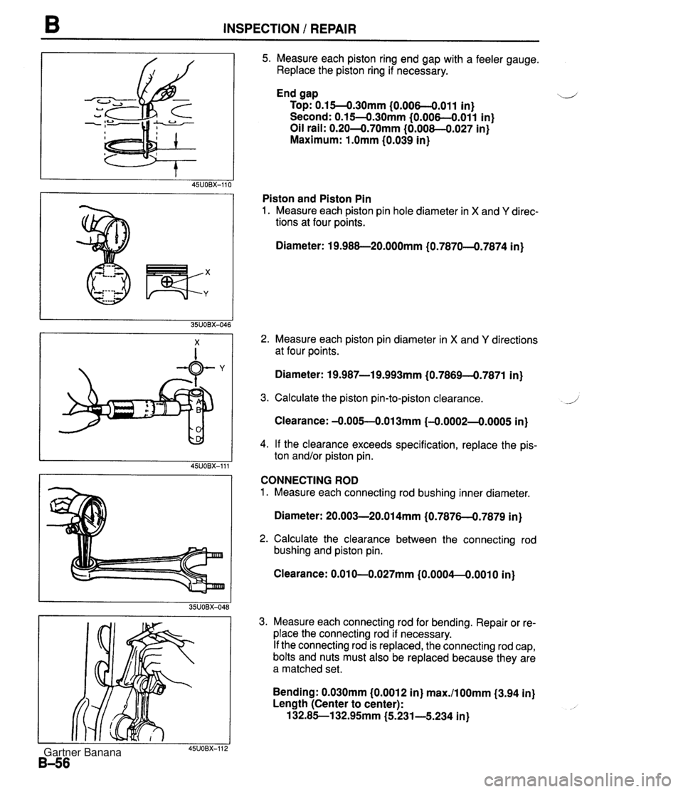
INSPECTION I REPAIR 5. Measure each piston ring end gap with a feeler gauge. Replace the piston ring if necessary. End gap \-.l Top: 0.15--0.30mm (0.006--0.011 in) Second: 0.1 54.3Omm (0.006--0.011 in) Oil rail: 0.204.70mm (0.008--0.027 in) Maximum: 1 .Omm (0.039 in) Piston and Piston Pin 1. Measure each piston pin hole diameter in X and Y direc- tions at four points. Diameter: 19.988-20.000mm (0.7870-4.7874 in) 2. Measure each piston pin diameter in X and Y directions at four points. Diameter: 19.987-1 9.993mm (0.7869-4.7871 in) 3. Calculate the piston pin-to-piston clearance. 1 Clearance: -0.005-0.01 3mm (-0.0002--0.0005 in) 4. If the clearance exceeds specification, replace the pis- ton and/or piston pin. CONNECTING ROD 1. Measure each connecting rod bushing inner diameter. Diameter: 20.003-20.014mm (0.7876-0.7879 in) 2. Calculate the clearance between the connecting rod bushing and piston pin. Clearance: 0.01 U.027mrn {O.OOO4--O.OOlO in) 3. Measure each connecting rod for bending. Repair or re- place the connecting rod if necessary. If the connecting rod is replaced, the connecting rod cap, bolts and nuts must also be replaced because they are a matched set. Bending: 0.030mm (0.0012 in) max./100mm (3.94 in) Length (Center to center): 132.85-1 32.9Smm (5.231-5.234 in) Gartner Banana
Page 94 of 1708

INSPECTION / REPAIR B MAIN JOURNAL I I DIMENSION R: 1.5mm (0.06 in} I CRANKSHAFT 1. Check the journals and pins for damage, scoring, and oil hole clogging. 2. Set the crankshaft on V-blocks. 3. Measure the crankshaft runout at the center journal. Replace the crankshaft if necessary. Runout: 0.04mm (0.0016 in) max. 4. Measure each journal diameter in X and Y directions at two points. Main journal Diameter: 49.938-49.956mm (1.9661-1.9667 in) Out-of-round: 0.05mm (0.0020 in) max. Crankpin journal Diameter: 44.94044.956mm 11.7693--1.7699 in) Out-of-round: 0.05mm (0.0020 in) max. 5. If the diameter is less than the minimum, grind the jour- nals to match an undersize bearing. Undersize bearing: 0.25mm (0.010 in), 0.50mm (0.020 in}, 0.75mm (0.030 in) Main journal diameter undersize mm {in) I bear in^ size I Diameter I 10.25 {0.010) undersize 1 49.70449.708 (1.9569--1.9570) 1 Main journal diameter undersize mm {in} 0.50 {0.010) undersize 0.75 {0.030) undersize I Bearing size I Diameter I 49.454--49.458 {I .9479-11.9471) 49.20449.208 11.9372-1.9373) ( 0.25 {0.010} undersize 1 44.690-44.706 {I .7595--1.7600) 1 BEARING Main Bearing and Connecting Rod Bearing Check the main bearings and the connecting rod bear- ings for peeling, scoring, and other damage. 0.50 {0.010) undersize - 0.75 (0.030) undersize 44.440-44.456 (1.7497-1.7502) 44.19044.206 (1.7398-1.7403) Gartner Banana
Page 95 of 1708

INSPECTION I REPAIR ee x 25rnrn (1.0 in) min DAMAGE WEAR TIMING BELT Caution The following will damage the belt and shorten its life; Forcefully twisting it, turning it inside out, bending it, or allowing oil or grease on it. 1. Replace the timing belt if there is any oil or grease on it. 2. Check the timing belt for damage, wear, peeling, cracks, and hardening. Replace the timing belt if necessary. TENSIONER, IDLER Caution Using cleaning fluids or a steam cleaner to clean the tensioner can dissolve the grease in its sealed bearing. \.-' Check the tensioner and idler for smooth rotation and abnormal noise. Replace the tensioner or idler if neces- sary. TENSIONER SPRING Measure the free length of the tensioner spring. Replace the tensioner spring if necessary. Free length: 59.2mm (2.331 in) PULLEY Timing Belt Pulley, Camshaft Pulley Inspect the pulley teeth for wear, deformation, and other damage. Replace the pulley if necessary. Gartner Banana
Page 96 of 1708

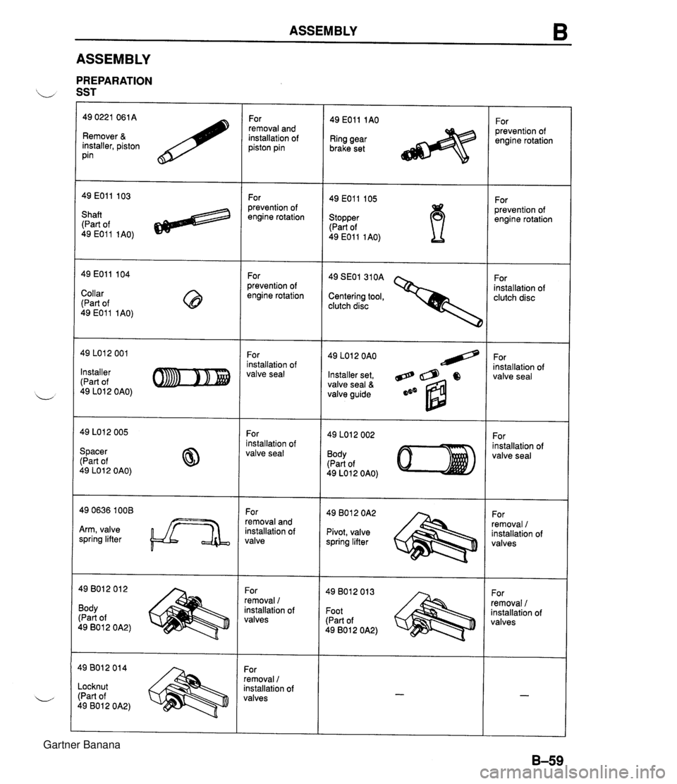
ASSEMBLY 6 ASSEMBLY PREPARATION SST 49 0221 061A Remover & installer, piston pin For removal and installation of piston pin 49 EOll 1AO For prevention of engine rotation Ring gear brake set For prevention of engine rotation For prevention of engine rotation 49 EOll 105 Stopper (Part of 49 EOll 1AO) Shaft (Part of 49 E011 1AO) For prevention of engine rotation For installation of clutch disc 49 SEOl 310A Centering tool, clutch disc Collar (Part of 49 E011 1AO) For installation of valve seal 49 LO1 2 OAO For installation of valve seal nstaller :Part of 49 LO1 2 OAO) Installer set, valve seal & valve guide For nstallation of rralve seal For installation of valve seal Body (Part of 49 LO 1 2 OAO) Spacer 'Part of $9 LOI 2 OAO) - -or 'emoval and nstallation of talve For removal / installation of valves irm, valve ;pring lifter Pivot, valve spring lifter 19 801 2 01 2 3ody Part of .9 80 1 2 0A2) -or emoval I nstallation of ralves For removal 1 nstallation of rralves Foot [Part of 49 801 2 0A2) .or emoval / istallation of 'alves .ocknut Part of 9 8012 0A2) Gartner Banana
Page 97 of 1708

ASSEMBLY 1. Do not reuse gaskets or oil seals. 2. Clean all parts before reinstallation. 3. Apply new engine oil to all sliding and rotating parts. 4. Replace plain bearings if they are peeled, burned, or otherwise damaged. 5. Tighten all bolts and nuts to the specified torques. CYLINDER BLOCK (INTERNAL PARTS) Torque Specifications CYLINDER WALLS I#- WASHER, NEW JOURNALS AND BEARINGS NEW Connecting Rod and Piston Assembly 1. Install one piston pin clip into the clip groove in the pis- ton. 2. Assemble the piston and the connecting rod. 3. Apply clean engine oil to the piston pin. 4. Install the piston pin from the side opposite the clip. 5. Tap the piston pin in with the SST until the pin contacts the clip. . , If the pin cannot be installed easily, replace the connect- ing rod. 6. Install the second clip into the clip groove in the piston. Gartner Banana
Page 98 of 1708

ASSEMBLY B SPACER TANG UPPER RAIL ...-.. OIL RlNG SPACER ENDS LOWER RAlL PISTON OIL RlNG UPPER RAIL TOP RING OIL RING + PISTOI PIN OIL RING. SECOND LOWER RAIL RING 7. Check the oscillation torque of the connecting rod. If the large end does not drop by its own weight, replace the piston and/or piston pin. Piston Ring 1. Install the three-piece oil rings on the pistons. (1) Apply clean engine oil to the oil ring spacer and rails. (2) lnstall the oil ring spacer with the ends upward. Note The upper and lower rails are the same. They can be installed with either face upward (3) Install the upper and lower rails. 2. Verify that the spacer tang separates the rails, and that the rails turn smoothly in both directions. 3. lnstall the rings with the R marks upward. 4. Using a piston ring expander, install the second ring with the scraper face downward. 5. Using a piston ring expander, install the top ring. 6. Apply clean engine oil to the top and second piston rings. 7. Position the end gaps of the rings as shown in the figure. Gartner Banana
Page 99 of 1708

B ASSEMBLY I PLASTIGAGE I Oil Jet lnstall the oil jets. Tightening torque: 12-1 7 N.m (1.2-1.8 kgf.m, 9-1 3 ft4bf) Crankshaft 1. Before installing the crankshaft, inspect the main bear- ing oil clearances as follows. Oil clearance inspection (1) Remove all foreign material and oil from the journals and bearings. (2) lnstall the grooved upper main bearings in the cylin- der block. (3) lnstall the thrust bearings with the oil groove facing the crankshaft. (4) Set the crankshaft in the cylinder block. (5) Position plastigage atop the journals in the axial direction. (6) Do not rotate the crankshaft when measuring the oil clearances. Install the lower main bearings and the main bearing caps according to the cap number and + mark. Tighten the main bearing cap bolts in two or three steps in the order shown in the figure. Tightening torque: 54--58 N-m I5.5--6.0 kgf.m, 40-43 ft4bf) (9) Remove the main bearing caps, and measure the plastigage at each journal at the widest point for the smallest clearance, and at the narrowest point for the largest clearance. (10) If the oil clearance exceeds specification, grind the crankshaft and use undersize main bearings. (Refer to page B-57.) , d' Oil clearance: 0.018-0.036mm (0.0008--0.0014 in) Maximum: 0.lOmm (0.004 in) Gartner Banana
Page 100 of 1708

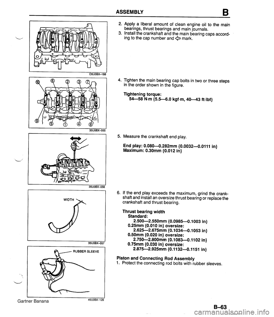
ASSEMBLY B I RUBBER SLEEVE 2. Apply a liberal amount of clean engine oil to the main bearings, thrust bearings and main journals. 3. Install the crankshaft and the main bearing caps accord- ing to the cap number and + mark. 4. Tighten the main bearing cap bolts in two or three steps in the order shown in the figure. Tightening torque: 54--58 N.m (5.5-6.0 kgf.m, 40-43 ft4bf) 5. Measure the crankshaft end play. End play: 0.080-0.282mm (0.0032-0.0111 in) Maximum: 0.30mm (0.012 in) 6. If the end play exceeds the maximum, grind the crank- shaft and install an oversize thrust bearing or replace the crankshaft and thrust bearing. Thrust bearing width Standard: 2.500-2.550mm (0.0985-0.1 003 in) 0.25mm (0.01 0 in) oversize: 2.625--2.675mm (0.1 034-O.1053 in) 0.50mm (0.020 in) oversize: 2.750-2.800mm (0.1 083-0.1 102 in) 0.75mm (0.030 in) oversize: 2.875-2.925mm (0.1 132-0.1151 in) Piston and Connecting Rod Assembly 1. Protect the connecting rod bolts with rubber sleeves. Gartner Banana