MAZDA MX-5 1994 Manual PDF
MX-5 1994
MAZDA
MAZDA
https://www.carmanualsonline.info/img/28/57072/w960_57072-0.png
MAZDA MX-5 1994 Manual PDF
Trending: tire type, oil pressure, transmission oil, audio, recommended oil, bolt pattern, wheel alignment
Page 71 of 1708
ENGINE STAND MOUNTING 2. Install the SST (arms) to the holes as shown in the fig- ure, and hand tighten the SST (bolts). 3. Assemble the SST (bolts and plate) in the specified position. 4. Assemble the SST (nuts, hooks, and bolts). 5. Install the SST to the respective arms. 6. Adjust the SST (bolts) so that less than 20mm (0.79 in) of thread is exposed. 7. Make the SST (plate and arms) parallel by adjusting the SST (bolts and nuts). 8. Tighten the SST (bolts and nuts) to affix the SST firmly. 9. Mount the engine on the SST (engine stand). Gartner Banana
Page 72 of 1708

DISASSEMBLY B DISASSEMBLY PREPARATION SST 49 EOll 1AO For prevention of engine rotation 49 EOll 103 For prevention of engine rotation Ring gear brake set Shaft (Part of 49 EOl 1 1 AO) 49 E011 105 Stopper (Part of 49 EOll lAO) a For prevention of engine rotation 49 EOll 104 For prevention of engine rotation Collar (Part of 49 E011 1 AO) For removal / installation of valves 49 8012 012 Body (Part of 49 801 2 0A2) For removal I installation of valves Pivot, valve spring lifter For removal / installation of valves For removal / installation of valves Foot (Part of 49 80 1 2 0A2) Locknut (Part of 49 B012 0A2) For removal / installation of valves 49 S120 170 Remover, valve seal For removal of valve seals Arm, valve spring lifter 49 0221 061 A Remover & installer, piston pin For removal / installation of piston pins 1. Code all identical parts (such as piston, piston rings, connecting rods, and valve springs) so that they can be reinstalled in the cylinder from which they were removed. 2. Clean the parts with a steam cleaner. Blow off any remaining water with compressed air. 45UOBX-065 Gartner Banana
Page 73 of 1708
DISASSEMBLY AUXILIARY PARTS 1. Drain the engine oil. 2. Disassemble in the order shown in the figure. 1. Ignition coil and high-tension lead 2. Crankshaft position sensor 3. Manifold bracket 4. Intake manifold assembly 5. Alternator 6. Alternator bracket 7. Right engine mount 8. Oil filter 9. Oil cooler 10. Oil pressure switch 11. Water outlet pipe 12. Spark plug 13. Dipstick and pipe 14. Engine hanger Gartner Banana
Page 74 of 1708
DISASSEMBLY B TIMING BELT Disassemble in the order shown in the figure, referring to Disassembly Note. 1. Water pump pulley 2. Crankshaft pulley, plate 3. Cylinder head cover 4. Upper timing belt cover 5. Middle timing belt cover 6. Lower timing belt cover 7. Pulley lock bolt Disassembly Note ... 8. Pulley boss 9. Timing belt .......... Disassembly Note page 538 ................. Inspection page 558 10. Tensioner, tensioner spring ................. Inspection page B-58 11. Idler ................. Inspection page B-58 page 8-38 12. Timing belt pulley ................. Inspection page 558 Gartner Banana
Page 75 of 1708
DISASSEMBLY ROTATION ARROW - Disassembly Note Pulley lock bolt 1. Hold the flywheel (MT) or drive plate (AT 2. Loosen the pulley lock bolt. 3. Remove the pulley lock bolt. ') with the SST. Timing belt 1. ~rGect the tensioner with a rag. 2. Loosen the tensioner lock bolt. Ply the tensioner out- ward with a bar. 3. Tighten the lock bolt with the tensioner spring fully ex- tended. 4. Mark the timing belt rotation for proper reinstallation. 5. Remove the timing belt. Gartner Banana
Page 76 of 1708

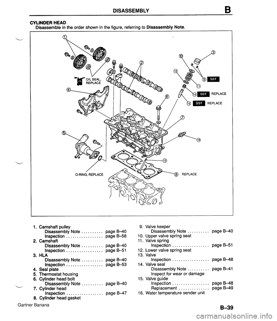
DISASSEMBLY B CYLINDER HEAD Disassemble in the order shown in the figure, referring to Disassembly Note. 1. Camshaft ~ullev 9. Valve keeper .......... ~isassembl~ Note .......... page B-40 isa assembly Note page I340 Inspection ................. page B-58 10. Upper valve spring seat . - 2. camshaft 11. Valve spring ................. Disassembly Note .......... page B-40 Inspection page 6-51 Inspection ................. page B-51 1 2. Lower valve spring seat 3. HLA 13. Valve ................. Disassembly Note .......... page B-40 Inspection page 8-48 Inspection ................. page 8-53 14. Valve seal .......... 4. Seal plate Disassembly Note page B-41 5. Thermostat housing Inspect for wear or damage 6. Cylinder head bolt 15. Valve guide ................. Disassembly Note .......... page 6-40 Inspection page B-48 i/ .............. 7. Cylinder head Replacement page B-49 ................. Inspection page B-47 16. Water temperature sender unit 8. Cylinder head gasket Gartner Banana
Page 77 of 1708
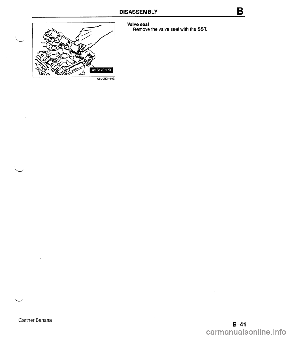
DISASSEMBLY Disassembly Note Camshaft pulley 1. Hold the camshaft with a wrench at the cast hexagon. 2. Remove the camshaft pulley lock bolts. 3. Remove the camshaft pulleys. Camshaft 1. Loosen the camshaft cap bolts in two or three steps in the order shown in the figure. 2. Remove the camshaft caps. 3. Remove the camshafts. 4. Remove the camshaft oil seals from the camshafts. HLA Caution The HLA must be reinstalled in the same position from which they were removed. If they are not, it can cause premature and uneven wear. L Note Mark the HLA to show their original positions. Remove the HLA from the cylinder head. Cylinder head bolt 1. Loosen the cylinder head bolts in two or three steps in the order shown in the figure. 2. Remove the cylinder head bolts. Valve keeper 1. Set the SST against the upper valve spring seat as shown in the figure. 2. Compress the spring and remove the valve keepers. Gartner Banana
Page 78 of 1708
DISASSEMBLY B Valve seal Remove the valve seal with the SST. Gartner Banana
Page 79 of 1708
B DISASSEMBLY CYLINDER BLOCK (EXTERNAL PARTS) Disassemble in the order shown in the figure, referring to Disassembly Note. GASKET, REPLACE - L 1. Clutch cover, clutch disc (MT) Removal 1 Installation ......... section H 2. Flywheel (MT), drive plate (AT) Disassembly Note .......... page 8-43 3. End plate 4. Oil pan Disassembly Note .......... page B43 5. Oil strainer 6. Oil pan baffle Disassembly Note .......... page B-44 7. Water pump 8. Oil pump ...... Disassembly 1 Assembly section D 9. Front oil seal Disassembly Note .......... page B-43 10. Rear cover 11. Rear oil seal Disassembly Note .......... page 6-43 Gartner Banana
Page 80 of 1708
DISASSEMBLY B PROTECT PUMP BODY WlTH RAG 05UOBX-10; I PROTECT REAR COYER WITH RAG I Disassembly Note Flywheel (MT) or drive plate (AT) 1. Hold the flywheel with the SST. 2. Remove the flywheel lock bolts. 3. Remove the flywheel. Oil pan 1. Remove the oil pan mounting bolts. Caution Pry tools can easily scratch the cylinder block and oil pan contact surfaces. 2. Insert a screwdriver only at the points shown in the fig- ure. 3. Remove the oil pan. Oil pan baffle 1. Insert a screwdriver between the cylinder block and the baffle to separate them. 2. Remove the baffle. Front oil seal Remove the oil seal with a screwdriver protected with a rag. Rear oil seal Remove the oil seal with a screwdriver protected with a rag. Gartner Banana
Trending: wiring, seats, wheel size, fuel tank capacity, wheel alignment, headlight bulb, flat tire


