MAZDA MX-5 1994 Repair Manual
Manufacturer: MAZDA, Model Year: 1994, Model line: MX-5, Model: MAZDA MX-5 1994Pages: 1708, PDF Size: 82.34 MB
Page 51 of 1708

ON-VEHICLE MAINTENANCE Installation Note Tensioner and tensioner spring 1. Install the tensioner and the tensioner spring. 2. Protect the tensioner with a rag. Pry the tensioner out- -,, ward with a bar. 3. Temporarily tighten the tensioner lock bolt with the ten- sioner spring fully extended. Timing belt 1. Verify that the timing belt pulley mark is aligned with the timing mark. 2. Verify that the camshaft pulley marks are aligned with the seal plate marks. E for intake side, and I for exhaust side. 3. Install the timing belt so that there is no looseness at the idler side or between the camshaft pulleys. 4. Install the pulley boss and pulley lock bolt. 5. Turn the crankshaft two turns clockwise and face the pin on the pulley boss upright. Do not turn the crankshaft counterclockwise. 6. Verify that the camshaft pulley marks are again aligned with the seal plate marks. If not aligned, remove the timing belt and repeat from tensioner installation. 7. Turn the crankshaft 1 and 516 turns clockwise and align the timing belt pulley mark with the tension set mark for proper timing belt tension adjustment. 8. Using the SST, loosen the pulley lock bolt and remove the bolt and pulley boss. Do not turn the crankshaft. 9. Verify that the timing belt pulley mark is aligned with the tension set mark. Gartner Banana
Page 52 of 1708

ON-VEHICLE MAINTENANCE B Stem After Installation 10. Loosen the tensioner lock bolt to apply spring tension to the timing belt. 11. Tighten the tensioner lock bolt. Tightening torque: 38-51 N-m (3.8-5.3 kgf.m, 28--38 ftlbf) 12. Install the pulley boss and pulley lock bolt. 13. Turn the crankshaft 2 and 116 turns clockwise and verify that the timing marks are correctly aligned. 14. Measure the timing belt deflection by applying moderate pressure 98 N (10 kgf, 22 Ibf) midway between the cam- shaft pulleys. If the deflection is not correct, repeat from Step 10 above. Deflection: 9.0-11.5mm (0.36-4.45 in) at 98 N (10 kgf, 22 Ibf) Pulley lock bolt Hold the crankshaft with the SST and tighten the pulley lock bolt. Tightening torque: 157-166 N.m (16-17 kgf.m, 116-122 ftlbf) 1. till the radiator with specified amount and type of engine coolant. (Refer to section E.) 2. Connect the negative battery cable. 3. Start the engine and check, and if necessary, adjust the ignition timing. Gartner Banana
Page 53 of 1708

ON-VEHICLE MAINTENANCE CYLINDER HEAD GASKET Replacement Warning e Fuel line spills and leaks are dangerous. Fuel can ignite and cause serious injuries or death and damage. Fuel can also irritate skin and eyes. To prevent this, always complete the "Fuel Line Safety Procedures" on section F. Fuel vapor is hazardous. It can very easily ignite, causing serious injury and damage. Always keep sparks and flames away from fuel. 1. Disconnect the negative battery cable. 2. Drain the engine coolant. (Refer to section E.) 3. Remove in the order shown in the figure, referring to Removal Note. 4. Install in the reverse order of removal, referring to Installation Note. Gartner Banana
Page 54 of 1708

ON-VEHICLE MAINTENANCE -- 1. Air cleaner housing assembly 2. Accelerator cable Installation Note ............. section E ,, 3. Hoses Removal / Installation Note ....... below 4. Harnesses Removal / lnstallation Note . . page El 8 5. Exhaust manifold insulator 6. Water bypass pipe nut Removal Note ............. page El8 7. Timina belt ~&moval/ Installation ....... page 51 2 Removal / lnstallation Note Hoses Disconnect the hoses shown in the figure. 8. Front exhaust pipe 9. Manifold bracket 10. Cylinder head bolt Removal Note ............. page 518 Installation Note ........... page 519 11. Cylinder head Disassembly .............. page 539 Inspection ................. page B-47 ................. Assembly page 6-69 12. Cylinder head gasket 45UOBX-035 Gartner Banana
Page 55 of 1708

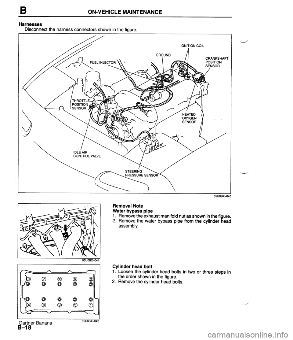
ON-VEHICLE MAINTENANCE Harnesses Disconnect the harness connectors shown in the figure. Removal Note Water bypass pipe 1. Remove the exhaust manifold nut as shown in the figure. 2. Remove the water bypass pipe from the cylinder head assembly. Cylinder head bolt 1. Loosen the cylinder head bolts in two or three steps in the order shown in the figure. 2. Remove the cylinder head bolts. Gartner Banana
Page 56 of 1708

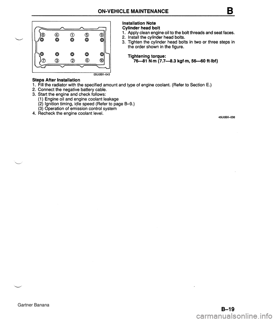
ON-VEHICLE MAINTENANCE B Installation Note Cylinder head bolt I I 05UOBX-043 Stem After Installation Apply clean engine oil to the bolt threads and seat faces. Install the cylinder head bolts. Tighten the cylinder head bolts in two or three steps in the order shown in the figure. Tightening torque: 76-81 N.m (7.7-8.3 kgf-m, 56-60 ft4bf) 1. pill the radiator with the specified amount and type of engine coolant. (Refer to Section E.) 2. Connect the negative battery cable. 3. Start the engine and check follows: (1) Engine oil and engine coolant leakage (2) Ignition timing, idle speed (Refer to page B-9.) (3) Operation of emission control system 4. Recheck the engine coolant level. Gartner Banana
Page 57 of 1708

ON-VEHICLE MAINTENANCE HLA Removal / lnstallation 1. Disconnect the negative battery cable. 2. Drain the engine coolant. (Refer to section E.) 3. Remove in the order shown in the figure, referring to Removal Note. 4. Install in the reverse order of removal, referring to lnstallation Note. 1. Timing belt Removal / Installation ....... page 51 2 2. Crankshaft position sensor Installation Note ............. section G 3. Camshaft pulley Removal Note ............. page 521 Installation Note ........... page 522 4. Camshaft Removal Note ............. page B-21 Installation Note ........... page B-21 5. HLA 1 Removal Note ............. page B-21 Installation Note ........... page B-21 Inspection ................. page B-53 Gartner Banana
Page 58 of 1708

ON-VEHICLE MAINTENANCE B CRANKSHAFT POSITION SENSOR DRIVE GROOVE 45UOBX-04 Removal Note Camshaft pulley 1. Hold the camshaft with a wrench at the cast hexagon. 2. Remove the camshaft pulley lock bolts. 3. Remove the camshaft pulleys. Camshaft 1. Loosen the camshaft cap bolts in two or three steps in the order shown in the figure. 2. Remove the camshaft caps. 3. Remove the camshafts. 4. Remove the camshaft oil seals from the camshafts. HLA Caution The HLA must be reinstalled in the same posi- tions from which they were removed. If they are not, it can cause premature and uneven wear. Note Mark the HLA to show their original positions. Remove the HLA from the cylinder head. Installation Note HLA 1. Apply clean engine oil to the friction surfaces. 2. If the HLA are being reused, install them in the position from which they were removed. 3. Verify that the HLA move smoothly in their bores. Camshaft Note The exhaust camshaft has a groove for the crank- shaft position sensor drive. 1. Apply clean engine oil to the camshaft journals and bear- ings. 2. Install the camshaft in position. Gartner Banana
Page 59 of 1708

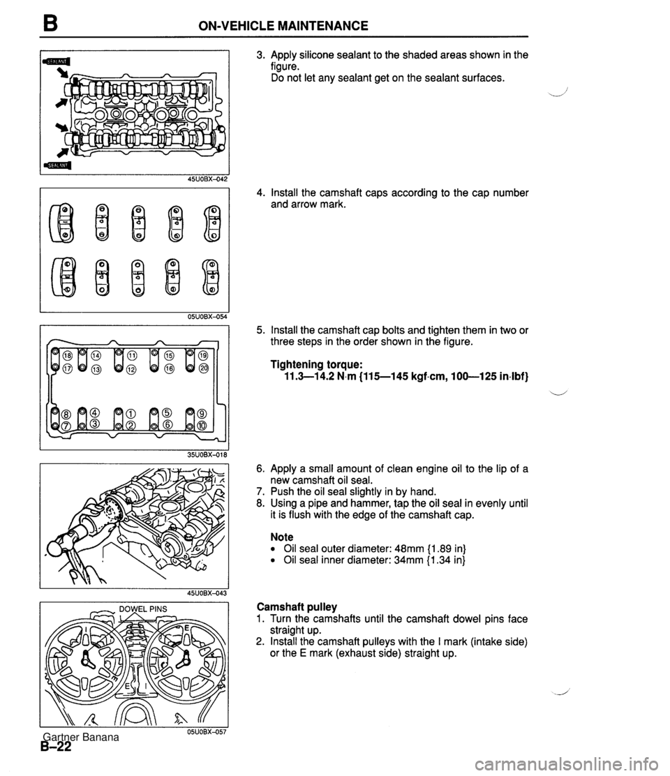
B ON-VEHICLE MAINTENANCE I - DOWEL PINS I 3. Apply silicone sealant to the shaded areas shown in the figure. Do not let any sealant get on the sealant surfaces. 4. Install the camshaft caps according to the cap number and arrow mark. 5. Install the camshaft cap bolts and tighten them in two or three steps in the order shown in the figure. Tightening torque: 11.3-1 4.2 N.m (115--145 kgf.cm, 100-125 in-lbf} ii 6. Apply a small amount of clean engine oil to the lip of a new camshaft oil seal. 7. Push the oil seal slightly in by hand. 8. Using a pipe and hammer, tap the oil seal in evenly until it is flush with the edge of the camshaft cap. Note Oil seal outer diameter: 48mm {I .89 in) Oil seal inner diameter: 34mm {I .34 in} Camshaft pulley 1. Turn the camshafts until the camshaft dowel pins face straight up. 2. Install the camshaft pulleys with the I mark (intake side) or the E mark (exhaust side) straight up. Gartner Banana
Page 60 of 1708

ON-VEHICLE MAINTENANCE B I I 35UOBX-020 Stem After Installation 3. Install the camshaft pulley lock bolts. 4. Hold the camshaft with a wrench at the cast hexagon. 5. Tighten the camshaft pulley lock bolt. Tightening torque: 50-60 Nm C5.0-6.2 kgfm, 3744 ft4bf) 1. pill the radiator with the specified amount and type of engine coolant. (Refer 2. Connect the negative battery cable. 3. Start the engine and check follows: (1) Engine coolant leakage (2) Ignition timing (Refer to page 59.) 4. Recheck the engine coolant levels. to section E.) Gartner Banana