MAZDA MX-5 1994 Repair Manual
Manufacturer: MAZDA, Model Year: 1994,
Model line: MX-5,
Model: MAZDA MX-5 1994
Pages: 1708, PDF Size: 82.34 MB
MAZDA MX-5 1994 Repair Manual
MX-5 1994
MAZDA
MAZDA
https://www.carmanualsonline.info/img/28/57072/w960_57072-0.png
MAZDA MX-5 1994 Repair Manual
Trending: run flat, bolt pattern, interior lights, ignition, spark plugs replace, key, oil type
Page 61 of 1708
B ON-VEHICLE MAINTENANCE FRONT OIL SEAL Replacement 1. Disconnect the negative battery cable. 2. Remove the under cover. 3. Remove in the order shown in the figure, referring to Removal Note. 4. Install in the reverse order of removal, referring to lnstallation Note. 1. Timing belt 3. Oil seal i Removal / Installation ....... page B-12 Removal Note ............. page 525 2. Timing belt pulley Installation Note ........... page B-25 Installation Note ........... page 8-25 Gartner Banana
Page 62 of 1708
ON-VEHICLE MAINTENANCE B Steps After Installation 1. Connect the neaative batterv cable. Oil seal 1. Cut the oil seal lip with a razor knife. 2. Remove the oil seal with a screwdriver protected with a rag. Installation Note Oil seal 1. Apply a small amount of clean engine oil to the lip of a new oil seal. 2. Push the oil seal slightly in by hand. 3. Tap the oil seal in evenly with a pipe and a hammer until it is flush with the edge of the oil pump body. Note Oil seal outer diameter: 50.5mm (1.99 in} Oil seal inner diameter: 36.5mm (1.44 in} Timing belt pulley 1. Install the timing belt pulley. 2. Install the pulley woodruff key with the tapered side to- ward the oil pump body. 2. Start the enginsand check, and if necessary, adjust the ignition timing. 3. Connect the negative battery cable. 4. Start the engine and check follows: (1) Engine coolant leakage (2) Ignition timing (Refer to page B-9.) 5. Recheck the engine coolant levels. Gartner Banana
Page 63 of 1708
B ON-VEHICLE MAINTENANCE REAR OIL SEAL Replacement 1. Disconnect the negative battery cable. 2. Remove the transmission. (MT Refer to section J. AT: Refer to section K.) 3. Remove in the order shown in the figure, referring to Removal Note. 4. Install in the reverse order of removal, referring to lnstallation Note. Nm (kgfm, ft-lbf) I 1. Clutch cover, clutch disc (MT) 4. Oil seal Removal / Installation ......... section H Removal Note .................. below 2. Flywheel (MT) Installation Note ........... page 6-27 ......... Removal / Installation section J 3. Drive plate (AT) ......... Removal / Installation section K Removal Note Oil seal 1. Cut the oil seal lip with a razor knife. 2. Remove the oil seal with a screwdriver protected with a rag. 05UOBX-063 Gartner Banana
Page 64 of 1708
ON-VEHICLE MAINTENANCE Installation Note Oil seal 1. Apply a small amount of clean engine oil to w new oil seal. 2. Push the oil seal slightly in by hand. 3. Using a pipe and hammer, tap the oil seal in it is flush with the edge of the rear cover. Note Oil seal outer diameter: 100mm (3.94 in} Oil seal inner diameter: 83mm (3.27 in} 45UOBX-049 Steps After Installation 1. Connect the negative battery cable. 2. Start the engine and perform engine adjustments as necessary. the lip of a evenly until Gartner Banana
Page 65 of 1708
B REMOVAL REMOVAL Caution Fuel line spills and leaks are dangerous. Fuel can ignite and cause serious injuries or death -d and damage. Fuel can also irritate skin and eyes. To prevent this, always complete the "Fuel Line safety Procedures" on section F. PROCEDURE 1. Disconnect the negative battery cable. 2. Drain the engine coolant. (Refer to section E.) 3. Remove the transmission. 4. Remove in the order shown in the figure, referring to Removal Note. Step 1 1. Air cleaner housing assembly 2. Accelerator cable 3. Radiator hose 4. Oil cooler hose 5. Coolant reservoir hose 6. Fan connector 7. Radiator and fan assembly 8. PIS andlor A/C drive belt ................ Removal 9. Alternator drive belt .................. Removal page B- 6 10. PIS oil pump (If equipped) ............. Removal Note page 529 11. AIC compressor (If equipped) Removal Note ............. page 529 1 page B- 6 Gartner Banana
Page 66 of 1708
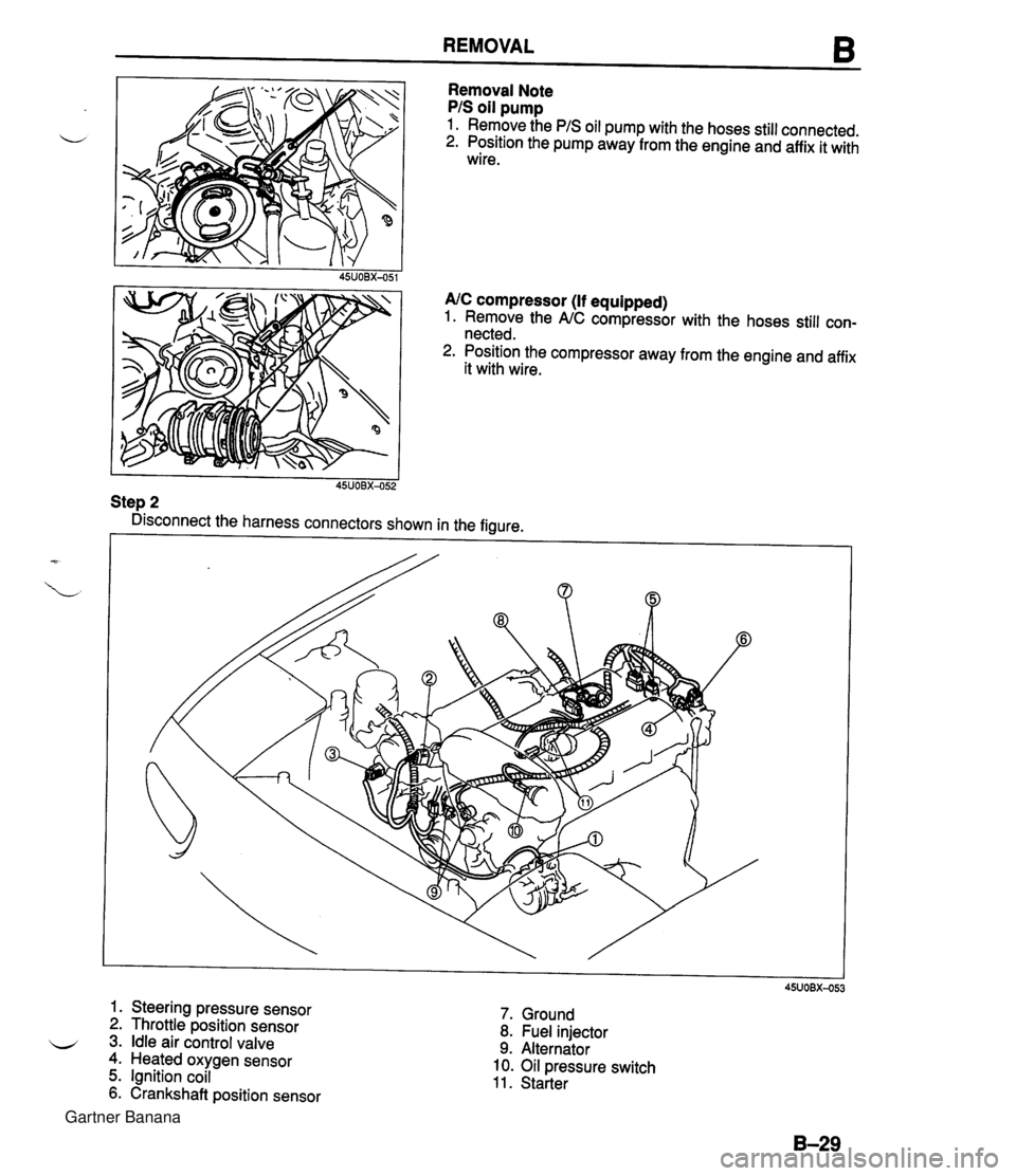
REMOVAL 6 Removal Note PIS oil pump 1. Remove the PIS oil pump with the hoses still connected. 2. Position the pump away from the engine and affix it with wire. 45UOBX-051 AIC compressor (If equipped) 1. Remove the NC compressor with the hoses still con- nected. 2. Position the compressor away from the engine and affix it with wire. I I 45UOBX-052 Step 2 Disconnect the harness connectors shown in the figure. 6 1. Steering pressure sensor 2. Throttle position sensor 3. Idle air control valve 4. Heated oxygen sensor 5. Ignition coil 6. Crankshaft position sensor 7. Ground 8. Fuel injector 9. Alternator 10. Oil pressure switch 11. Starter Gartner Banana
Page 67 of 1708
B REMOVAL is connect the hoses shown in the figure. 1. Brake vacuum hose 4. Vacuum hose (Cruise control) 2. Fuel hose 5. Water inlet hose Removal Note . . . . . . . . . . . . . . . . . . below 6. Heater hose 3. Vacuum hose (Purge control) Removal Note Fuel hose Warning Fuel vapor is hazardous. It can very easily ignite, causing serious injury and damage. Always keep sparks and flames away from fuel. Disconnect the fuel hoses. Gartner Banana
Page 68 of 1708
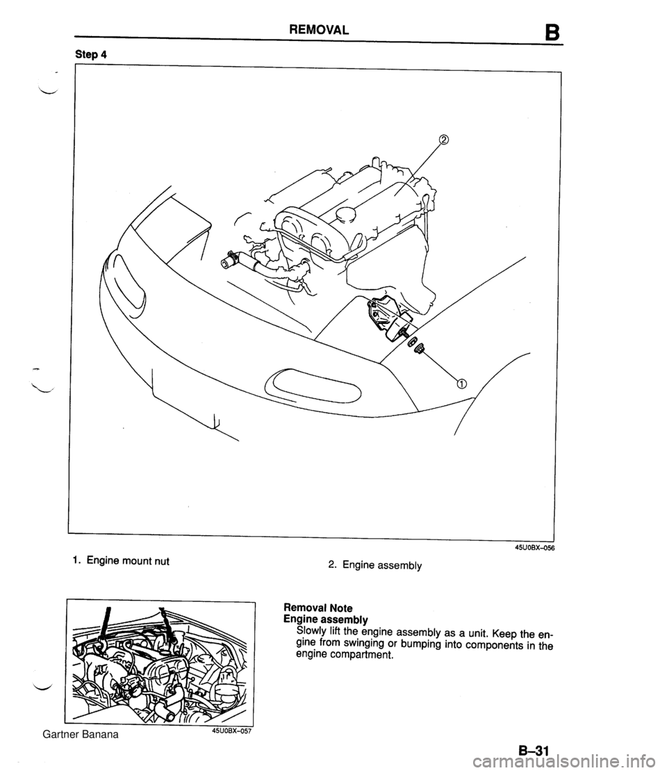
REMOVAL B Step 4 1. Engine mount nut 2. Engine assembly Removal Note Engine assembly Slowly lift the engine assembly as a unit. Keep the en- gine from swinging or bumping into components in the engine compartment. Gartner Banana
Page 69 of 1708
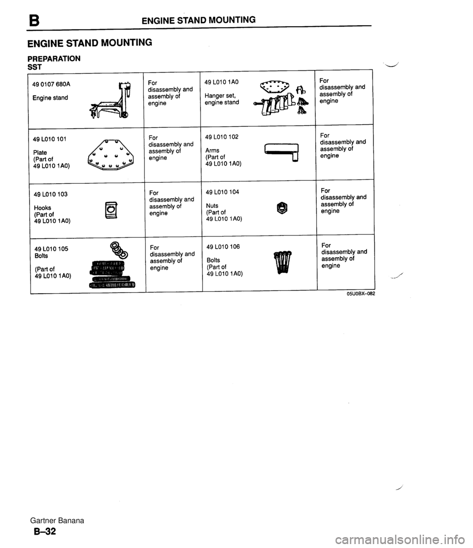
B ENGINE STAND MOUNTING ENGINE STAND MOUNTING PREPARATION SST 49 01 07 680A Engine stand Plate (Part of 49 LO1 0 1 AO) 49 LOlO 103 Hooks (Part of 49 LO1 0 1 AO) 49 LO10 105 Bolts (Part of 49 LO1 0 1 AO) For disassembly and assembly of engine For disassembly and assembly of engine For disassembly and assembly of engine For disassembly and assembly of engine 49 LOlO 1AO - Hanger set, fB engine stand &b A Arms (Part of 49 LO1 0 1 AO) 49 LOlO 104 Nuts (Part of 49 LO1 0 1 AO) 8 Bolts (Part of 49 LO1 0 1 AO) For disassembly and assembly of engine For disassembly and assembly of engine For disassembly and assembly of engine For disassembly and assembly of engine Gartner Banana
Page 70 of 1708
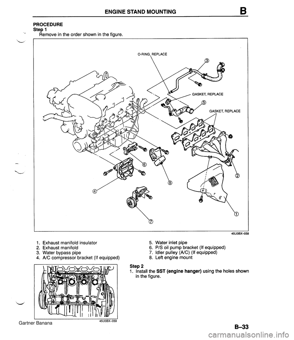
ENGINE STAND MOUNTING PROCEDURE Ste~ 1 ~emove in the order shown in the figure. O-RING,, REPLACE 1. Exhaust manifold insulator 5. Water inlet pipe 2. Exhaust manifold 6. PIS oil pump bracket (If equipped) 3. Water bypass pipe 7. Idler pulley (NC) (If equipped) 4. NC compressor bracket (If equipped) 8. Left engine mount Step 2 1. Install the SST (engine hanger) using the holes shown in the figure. Gartner Banana
Trending: coolant, fuel tank capacity, charging, fuse, maintenance schedule, brakes, AIR BAG


