service MAZDA MX-5 1994 Workshop Manual
[x] Cancel search | Manufacturer: MAZDA, Model Year: 1994, Model line: MX-5, Model: MAZDA MX-5 1994Pages: 1708, PDF Size: 82.34 MB
Page 1113 of 1708
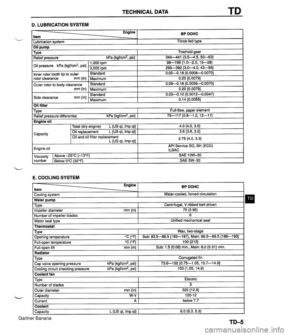
TECHNICAL DATA D. LUBRICATION SYSTEM - Engine ltem BP DOHC - -. Lubrication system Force-fed type E. COOLING SYSTEM Trochoid gear 344-41 I3.5--4.5,s-31 9&l96 {I .&2.0, 15--28) 295-392 {3.0-4.0,43-56) 0.02-0.1 8 {0.000&0.0070) 0.20 {0.0079) 0.09-0.18 (0.0036-0.0070) 0.20 {0.0079) 0.03-0.1 2 {0.0012-0.0047) 0.14 (0.0055) TY pe Relief pressure kPa {kgf/cm2, psi) Oil pressure kPa {kgf/cm2, psi) Inner rotor tooth tip to outer rotor clearance mm {in) Outer rotor to body clearance mm {in) Side clearance mm {in) Water seal type I Unified mechanical seal Thermostat 1,000 rpm 3,000 rpm Standard Maximum Standard Maximum Standard Maximum Oil filter Engine ltem - - Cooling system . . Impeller diameter mm {in) Number of impeller blades Type Relief pressure differential kPa {kgf/cm2, psi) BP DOHC Water-cooled, forced circulation - 75 i2.95) 6 Full-flow, paper element 74-1 17 {0.&1.2, 12-1 7) TY pe . ., . . . - Radiator I Water pump Wax, two-stage v. . . Full-open temperature "c {OF) Full-open lift mm {in) Engine oil TVD~ O~enina tem~erature "C con I Sub: 83.5-86.5 U83-187). Main: 86.5-89.5 (1 88-1 931 100 (21 2) Sub: 1.5 (0.06) min., Main: 8.0 (0.31) min. -. . - . . Cooling circuit checking pressure kPa {kgflcmz, psi) I 103 {I .05, 14.9) I Centrifugal, V-ribbed belt driven TY pe I Coolant fan I 4.0 (4.2, 3.5) 3.6 {3.8,3.2) 3.75 (4.0, 3.3) API Service SG, SH (ECII) ILSAC Capacity Corrugated fin viscosity Above -25°C (-1 3°F) SAE 1 OW-30 number Below 0°C {3Z°F) SAE 5W-30 Total (dry engine) L {US qt, Imp qt) Oil replacement L {US qt, Imp qt) Oil and oil filter replacement L {US qt, Imp qtl Cap valve o~enina pressure kPa {krrf/cm2, psi} 1 73.6--102 {0.75--1.05, 10.7-14.91 Capacity W-V I 120-1 2 Current A 1 below 7.7 Engine oil Type Number of blades Outer diameter mm {in) Coolant Capacity L {US qt, Imp qt) I 6.0 {6.3,5.3) Electric 5 320 (1 2.61 Gartner Banana
Page 1116 of 1708
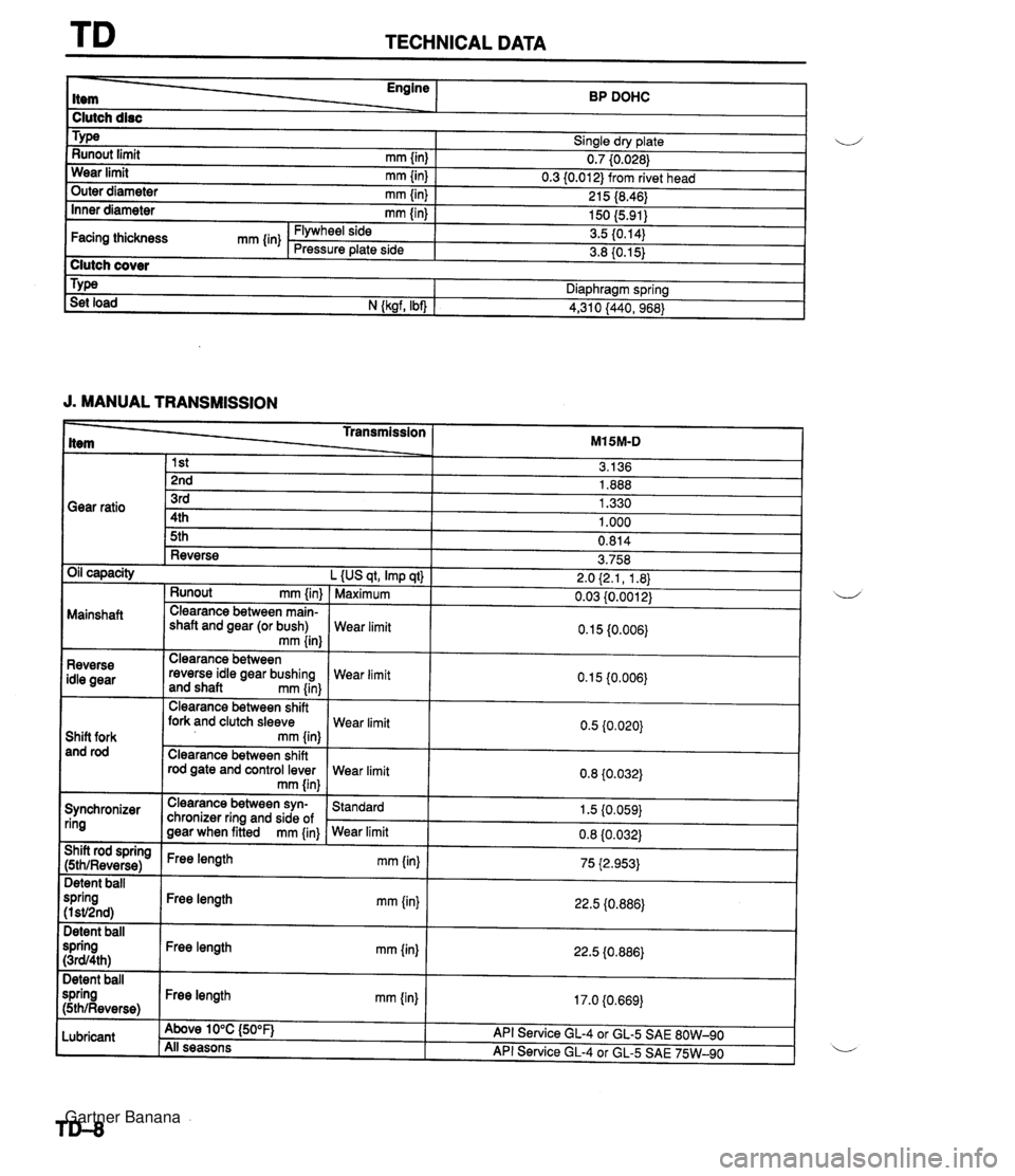
TECHNICAL DATA Engine ------ BP DOHC I Clutch disc I Sinale drv date I u - w- ., Runout limit rnrn {in) 0.7 (0.026) Wear limit rnm linl 0.3 10.01 2) from rivet head . a, 1 outer diameter mm {in) I 215 (8.46) 1 J. MANUAL TRANSMISSION 150 (5.91) 3.5 (0.14) 3.8 (0.15) Inner diameter mm {in) Type _____L- Transmission ___2_ M15M-D Clutch cover Facing thickness mm {in) Diaphragm spring Flywheel side Pressure plate side Set load N {ksrf. Ibn 1 4,310 /440. 968) Gear ratio Runout rnm {in) Mainshaft Clearance between main- shaft and gear (or bush) mm {in} t-- Reverse Oil capacity L {US qt, Imp qt) 1 Maximum 3rd 4th 5th 3.758 2.0 (2.1, 1.8) 0.03 10.001 2) Clearance between shift fork and clutch sleeve Shift fork and rod rod gate and control lever 1.330 1 .OOO 0.814 Reverse idle gear Clearance between reverse idle gear bushing and shaft mrn {in) Synchronizer ring Wear limit Wear limit Clearance between syn- chronizer ring and side of gear when fitted mm {in} Wear limit 0.1 5 {0.006) Wear limit Wear limit I 1 mm {in) ( 75 i2.953) Standard 1.5 (0.059) 22.5 (0.886) 22.5 i0.886) 17.0 (0.669) Detent ball spring (I sV2nd) Detent ball spring (3~94th) Detent ball spring (5thlReverse) Lubricant Free length mm (in) Free length mrn {in) Free length mm {in) Above 10°C {50°F} All seasons API Service GL-4 or GL-5 SAE 80W-90 API Service GL-4 or GL-5 SAE 75W-90 Gartner Banana
Page 1120 of 1708
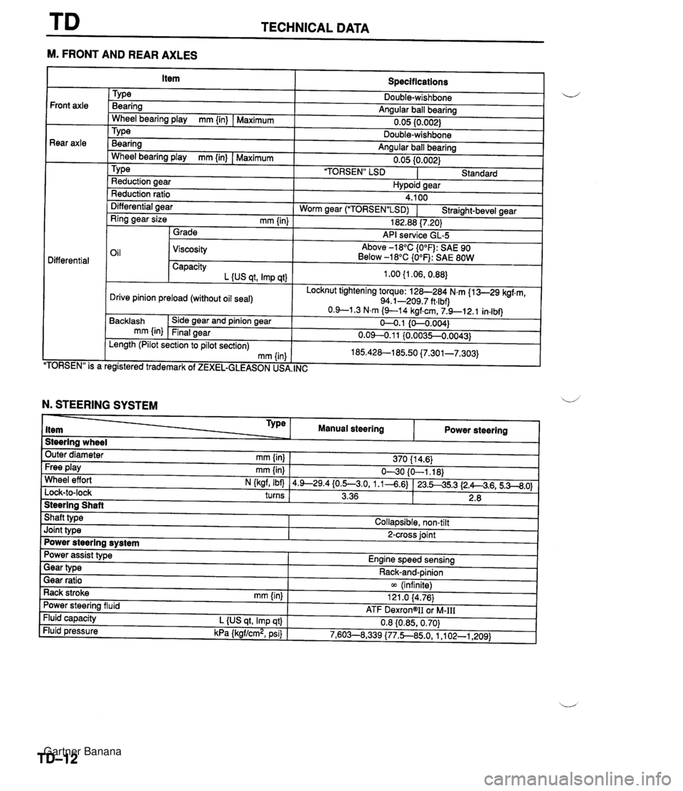
TECHNICAL DATA --- M. FRONT AND REAR AXLES Specifications TY pe Bearing Angular ball bearing 0.05 10.002) Front axle Rear axle - Wheel bearing play mm {in) I Maximum Bearina Anaular ball bearina . .. Wheel bearina plav mm {in) I Maximum " " 0.05 {0.002) 'TORSEN" LSD I Standard TY pe Reduction aear Hvpoid sear Reduction ratio Differential aear 4.100 Worm near ("1ORSEN"LSD) I Straiaht-bevel gear - - Ring gear size mm {in) 1 Grade 182.88 17.201 API service GL-5 Oil 1 Viscosity Above -18°C {O°F): SAE 90 Below -18°C {O°F): SAE 80W Differential Capacity L {US at. Imp at) Locknut tightening torque: 128-284 N.m {I 3-29 kgf.m, 94.1-209.7 ft.lbf) Drive pinion preload (without oil seal) TORSEN" is a Backlash mm {in) . , egistered trademark of ZEXEL-GLEASON US, Side gear and pinion gear Final gear , INC Length (Pilot section to pilot section) mm (in N. STEERING SYSTEM Steering wheel Outer diameter mm {in} 1 370 11 4.6) Type item Free play mm {in) I 630 {O-1.18) Wheel effort N (kaf, Ibfl 14.9--29.4{0.5--3.0, 1.1-4.6) 123.545.3 12.A4.6,5.3--8.0) turns I 3.36 1 2.8 I 1 Manual steering Steering Shaft Shaft type I Collapsible, non-tilt Power steering Joint type I 2-cross joint Power steering system Gear ratio 1 m (infinite) Rack stroke rnm {in) I 121 .O 14.76) Power assist type Engine speed sensing Power steering fluid Fluid capacity L {US qt, Imp qt} Fluid pressure kPa {kgf/cm2, psi) Gear type - - ATF DexrongII oi M-111 0.8 {0.85,0.70) 7,603--8,339 (77.5850, 1 ,I 02-1,209) Rack-and-pinion Gartner Banana
Page 1125 of 1708
SPECIAL TOOLS GENERAL INFORMATION The letters A and B in the priority column indicate the degree of importance of each tool. A . . . . . Indispensable u The tools ranked A in this list are indispensable for performing operations satisfactorily, easily, safely, and efficiently. It is, therefore, advisable that all service shops have these tools. B . . . . . Selective The tools ranked B are not as necessary as tools ranked A, but all service shops should have them to perform repairs more easily and efficiently. 25USTX-001 Gartner Banana
Page 1250 of 1708
Mazda MX-5 Body Shop Manual - FOREWORD This Bodyshop manual was prepared as refer- ence material of the service personnel of authorized Mazda dealers to enable them to cor- L- rectly carry out the task of rendering services on Mazda vehicles. In order to ensure that the customers are satis- fied with Mazda products, proper servicing must be provided. For this purpose, the service person- nel must fully understand the contents of this manual and at the same time, are recommended to keep the manual in a place where reference can readily be made. CONTENTS i- The information, photographs, drawings and specifications entered in this manual were the best available at the time of printing this manual. All alterations to this manual occurring as the result of modifications will be notified by the is- suance of Service Information or supplementary volumes. It is, therefore, requested that the manual be dept up to date by carefully maintain- ing a follow-up of these materials. Title -W Mazda Motor Corporation reserves the right to alter the specifications and contents of this manual without any obligation or advance notice. Page All rights reserved. No part of this book may be reproduced or utilized in any form or by any means, mechanical, including photocopying, recording, or by any informational storage and retrieval system without permission in writing. Mazda Motor Corporation HIROSHIMA, JAPAN 01989 Mazda Motor Corporation PRINTED IN JAPAN October, '890 3167-10-89J Gartner Banana
Page 1251 of 1708
GENERAL SERVICE INFORMATION SERVICE PRECAUTIONS ............................................ 2 JACKING AND SAFETY STAND POSITIONS ............ 8 VEHICLE LIFT (2-SUPPORT TYPE) POSITIONS ....... 8 TOW CABLE ATTACHMENT POSITIONS .................. 9 IDENTIFICATION NUMBER LOCATIONS ................... 9 VEHICLE DIMENSIONS ................................................ 10 WHEEL ALIGNMENT .................................................... 10 Gartner Banana
Page 1252 of 1708
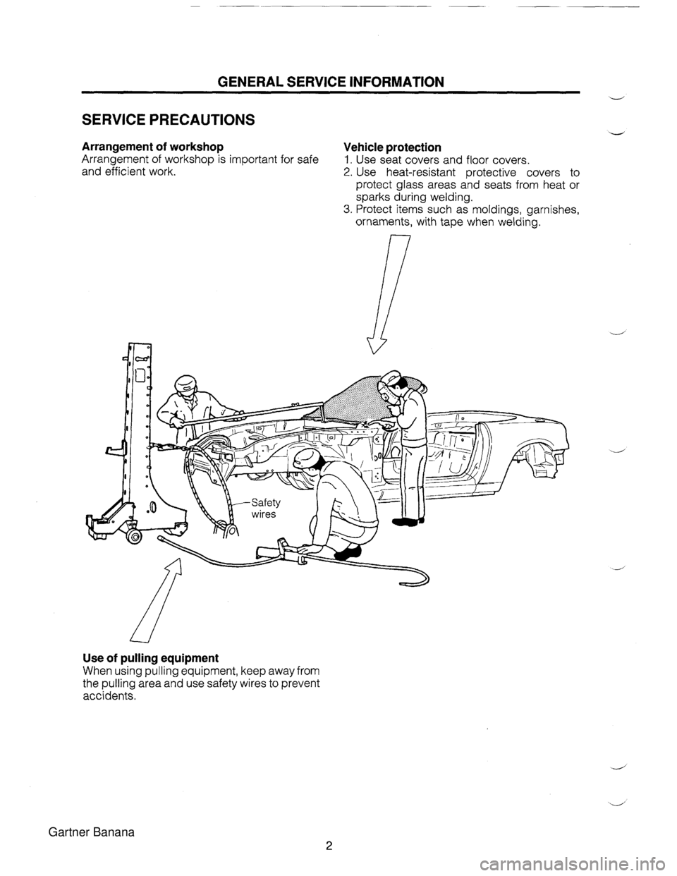
GENERAL SERVICE INFORMATION V SERVICE PRECAUTIONS V Arrangement of workshop Vehicle protection Arrangement of workshop is important for safe 1. Use seat covers and floor covers. and efficient work. 2. Use heat-resistant protective covers to protect glass areas and seats from heat or sparks during welding. 3. Protect items such as moldings, garnishes, ornaments, with tape when welding. Use of pulling equipment When using pulling equipment, keep away from the pulling area and use safety wires to prevent accidents. Gartner Banana
Page 1253 of 1708
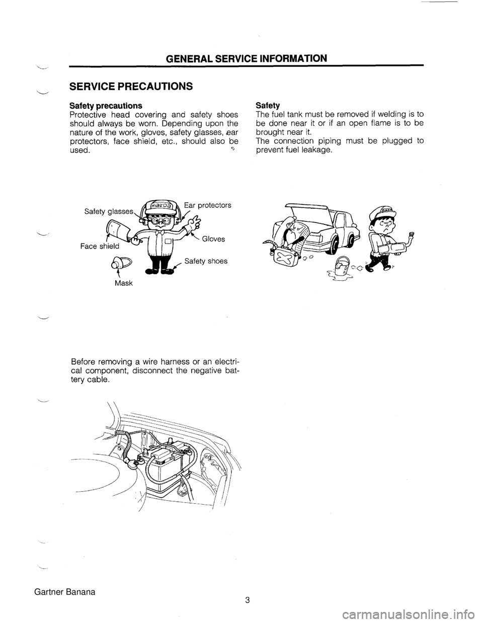
GENERAL SERVICE INFORMATION './ SERVICE PRECAUTIONS Safety precautions Safety Protective head covering and safety shoes The fuel tank must be removed if welding is to should always be worn. Depending upon the be done near it or if an open flame is to be nature of the work, gloves, safety glasses, ear brought near it. protectors, face shield, etc., should also be The connection piping must be plugged to used. -, prevent fuel leakage. Mask C_i Before removing a wire harness or an electri- cal component, disconnect the negative bat- tery cable. Gartner Banana
Page 1254 of 1708
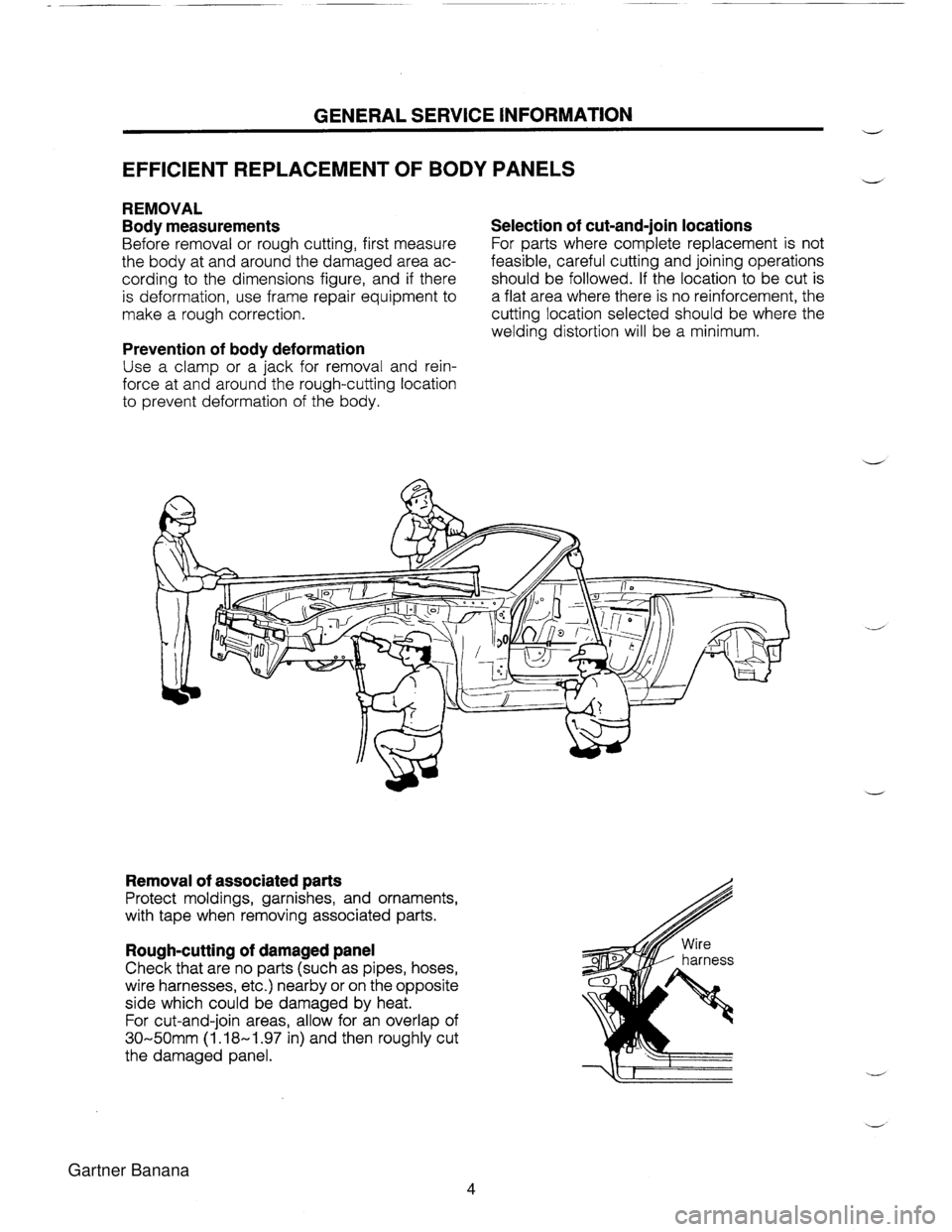
GENERAL SERVICE INFORMATION w EFFICIENT REPLACEMENT OF BODY PANELS V REMOVAL Body measurements Selection of cut-and-join locations Before removal or rough cutting, first measure For parts where complete replacement is not the body at and around the damaged area ac- feasible, careful cutting and joining operations cording to the dimensions figure, and if there should be followed. If the location to be cut is is deformation, use frame repair equipment to a flat area where there is no reinforcement, the make a rough correction. cutting location selected should be where the welding distortion will be a minimum. Prevention of body deformation Use a clamp or a jack for removal and rein- force at and around the rough-cutting location to prevent deformation of the body. Removal of associated parts Protect moldings, garnishes, and ornaments, with tape when removing associated parts. Rough-cutting of damaged panel Check that are no parts (such as pipes, hoses, wire harnesses, etc.) nearby or on the opposite side which could be damaged by heat. For cut-and-join areas, allow for an overlap of 30-50mm (1.18-1.97 in) and then roughly cut the damaged panel. Gartner Banana
Page 1255 of 1708
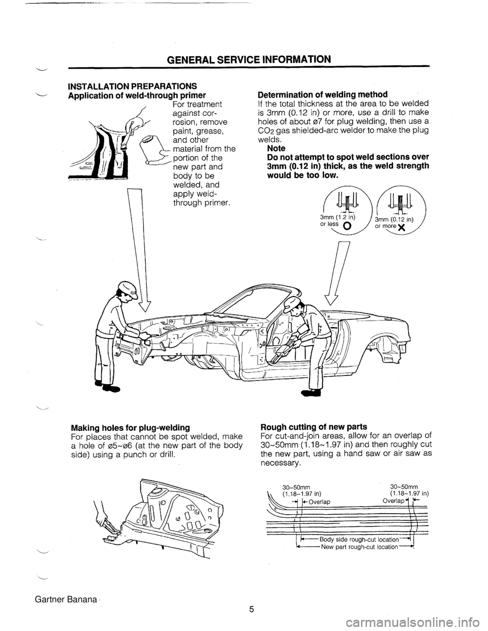
u GENERAL SERVICE INFORMATION INSTALLATION PREPARATIONS Application of weld-through primer 1 For treatment against cor- rosion, remove paint, grease, and other material from tl ,portion of the new part and body to be welded, and apply weld- Determination of welding method If the total thickness at the area to be welded is 3mm (0.12 in) or more, use a drill to make holes of about 07 for plug welding, then use a CO2 gas shielded-arc welder to make the plug welds. Note Do not attempt to spot weld sections over 3mm (0.12 in) thick, as the weld strength would be too low. or less Making holes for plug-welding Rough cutting of new parts For places that cannot be spot welded, make For cut-and-join areas, allow for an overlap of a hole of 05-06 (at the new part of the body 30-50mm (1.18-1.97 in) and then roughly cut side) using a punch or drill. the new part, using a hand saw or air saw as necessary. 30-50mm (1.18-1.97 in) (1.18-1.97 in) overlap Gartner Banana