lock MAZDA MX-5 1994 Workshop Manual
[x] Cancel search | Manufacturer: MAZDA, Model Year: 1994, Model line: MX-5, Model: MAZDA MX-5 1994Pages: 1708, PDF Size: 82.34 MB
Page 615 of 1708

M DIFFERENTIAL Installation note Differential 1. Connect the drive shaft to the output shaft with the marks aligned. 2. Install the differential. - JOMX- Tightening torque 0: 83-98 N-m (8.5-10 kgf.m, 61-72 ft4bf) @I: 18-26 N.m (1.8-2.7 kgf.m, 13-20 ft.lbf) 3. Adjust the rear wheel alignment if the upper arm installa- tion bolt and nut were removed. (section R.) Power plant frame (PPF) 1. Install the differential mounting spacer. Tightening torque: 37-52 N-m (3.8-5.3 kgf.m, 27-38 ftdbf} .i 2. Support the transmission with a jack so that it is level. 3. Position the PPF and snugly tighten the transmission- side bolts by hand. 4. Verify that the sleeve is installed into the block. 5. Install the spacer and bolts and snugly tighten them. The reamer bolt should be installed in the forward hole. 6. Snugly install the power plant frame bracket. 7. Tighten the transmission-side bolts. Tightening torque: lO4--123 N.m (1 0.6-1 2.6 kgf.m, 77-91 ft4bf) Gartner Banana
Page 618 of 1708

DIFFERENTIAL M 1. Output shafts Disassembly Note .......... page M-34 Assembly Note ............ page M-42 u 2. Differential case Disassembly Note .......... page M-34 Assembly Note ............ page M-42 3. Differential gear assembly Disassembly Note .......... page M-34 4. Lock plates 5. Bearing caps Disassembly Note .......... page M-34 Assembly Note ............ page M-42 6. Adjusting nuts Disassembly Note .......... page M-34 7. Bearing outer races (Side bearing) 8. Gear case assembly ("TORSEN" LSD) 9. Ring gear lnspect individual gear teeth for wear and cracks 10. Knock pin (Standard) Disassembly Note .......... page M-34 11. Pinion shaft (Standard) 12. Pinion gears (Standard) lnspect individual gear teeth for wear and cracks 13. Thrust washers (Standard) 14. Side gears (Standard) lnspect individual gear teeth for wear and cracks b 15. Thrust washers (Standard) Assembly Note ............ page M-40 16. Bearing inner races (Side bearing) Disassembly Note .......... page M-34 lnspect for damage and rough rotation 17. Gear case 18. Locknut (Companion flange) Disassembly Note .......... page M-35 19. Washer 20. Companion flange Disassembly Note .......... page M-35 lnspect splines for wear and damage 21. Oil seal (Companion flange) 22. Washer 23. Drive pinion Disassembly Note .......... page M-35 lnspect splines for wear and damage lnspect individual gear teeth for wear and cracks 24. Spacer Assembly Note ............ page M-37 25. Bearing inner race (Front bearing) lnspect for damage and rough rotation ............ Assembly Note page M-38 26. Collapsible spacer 27. Bearing outer race (Rear bearing) Disassembly Note .......... page M-35 Assembly Note ............ page M-37 28. Bearing outer race (Front bearing) Disassembly Note .......... page M-35 Assembly Note ............ page M-36 29. Bearing inner race (Rear bearing) Disassembly Note .......... page M-35 lnspect for damage and rough rotation Assembly Note ............ page M-37 30. Differential carrier 31. Oil seal (Output shaft) Assembly Note ............ page M-36 32. Baffle 33. Breather 34. Differential mount Disassembly Note .......... page M-36 Assembly Note ............ page M-36 45UOMX-053 Gartner Banana
Page 620 of 1708

DIFFERENTIAL id Locknut (Companion flange) Hold the companion flange by using the SST and remove the locknut. Companion flange Pull the companion flange off by using the SST. Drive pinion Push out the drive pinion by attaching a miscellaneous locknut to the drive pinion, and tapping it with a copper hammer. Bearing outer races (Front, and rear bearing) Remove the bearing outer races using the two grooves in the carrier and alternately tapping the sides of the races. Bearing inner race (Rear bearing) While supporting the drive pinion to keep it from falling, remove the bearing inner race (rear bearing) by using the SST. Gartner Banana
Page 623 of 1708

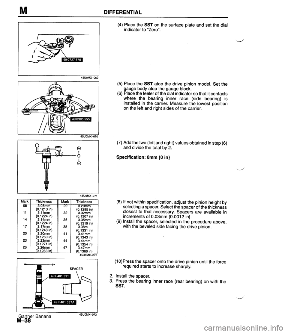
M DIFFERENTIAL (4) Place the SST on the surface plate and set the dial indicator to "Zero". (5) Place the SST atop the drive pinion model. Set the gauge body atop the gauge block. (6) Place the feeler of the dial indicator so that it contacts where the bearing inner race (side bearing) is installed in the carrier. Measure the lowest position on the left and right sides of the carrier. (7) Add the two (left and right) values obtained in step (6) and divide the total by 2. Specification: Omm (0 in) Thickness mm {tP2"13 in} 3.11mm (0.1 224 in} 3.14mm (0.1 224 in} 3.1 7mm (0. I248 in} 3.20mm (0.1260 in} 3.23mm (0.1271 in] 3.26mm 40.1283 in} Thickness rnm {t&5 in} 3.32mm (0.1307 in} 3.35mm (0.1319 in] 3.38m (0.1331 in) 3.41 mm (0.1343 in) 3.44mm {0.1354 in) 3.47rnm (0.1366 in) 45UOMX-47: (8) If not within specification, adjust the pinion height by selecting a spacer. Select the spacer of the thickness closest to that necessary. Spacers are available in increments of 0.03mm (0.001 2 in). (9) Install the spacer, selected in the procedure above, with the beveled side facing the drive pinion. (1 0)Press the spacer onto the drive pinion until the force SPACER required starts to increase sharply. 2. Install the sDacer. 3. Press the bearing inner race (rear bearing) on with the SST. Gartner Banana
Page 624 of 1708

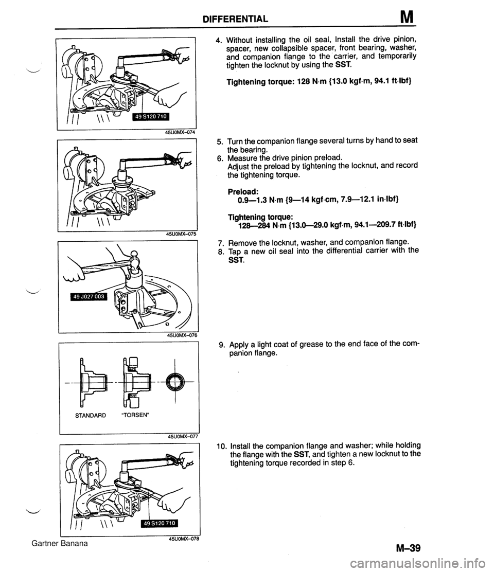
DIFFERENTIAL M 4. Without installing the oil seal, Install the drive pinion, spacer, new collapsible spacer, front bearing, washer, and companion flange to the carrier, and temporarily tighten the locknut by using the SST. Tightening torque: 128 N-m (13.0 kgf-m, 94.1 ft-lbf) 5. Turn the companion flange several turns by hand to seat the bearing. 6. Measure the drive pinion preload. Adjust the preload by tightening the locknut, and record the tightening torque. STANDARD "TORSEN" 45UOMX-07; Preload: 0.9-1.3 N.m (9-1 4 kgf.cm, 7.9-1 2.1 in4bf) Tightening torque: 128-284 N.m (13.0-29.0 kgf.m, 94.1-209.7 ft-lbf) 7. Remove the locknut, washer, and companion flange. 8. T~D a new oil seal into the differential carrier with the 9. Apply a light coat of grease to the end face of the com- panion flange. 10. Install the companion flange and washer; while holding the flange with the SST, and tighten a new locknut to the tightening torque recorded in step 6. Gartner Banana
Page 625 of 1708

M DIFFERENTIAL Thrust washers (Standard) 1. Adjust the backlash of the side gears and pinion gear as follows. (Standard) (1) Set a dial gauge against the pinion gear as shown. ,+, (2) Secure one of the side gears. (3) Move the pinion gear, and measure the backlash at the end of it. If not within specification, replace the dif- ferential gear as an assembly. ("TORSEN" LSD) Standard backlash: 04.1 mm (0-0.004 in) (4) If the backlash exceeds the standard, use the select- able thrust washers for adjustment. 2. Install the new knock pin to secure the pinion shaft. Stake the pin with a punch to prevent it from coming out of the case. Thrust washer thickness: 3. Apply thread-locking compound to bolt threads @ and points @I of the gear back face. Apply approximately 0.04 cm3 I0.04 cc, 0.0024 cu in} of thread-locking com- pound at each point and bolt thread. 4. lnstall the ring gear onto the gear case. Identification mark 0 0.5 1 1.5 2 Tightening torque: 69-83 N.m (7.0--8.5 kgf-m, 51-61 ft-lbf) Thickness 2.00mm i0.0787 in} 2.05mm (0.0807 in) 2.10mm {0.0827 in) 2.15mm (0.0846 in} 2.20mm i0.0866 in} 5. Press the bearing inner races (side bearing) on by using the SST. 6. Install the differential gear assembly in the carrier. 7. Note the identification marks on the adjusting nuts, and install them on their respective sides. 8. lnstall the differential bearing caps, making sure that the identification mark on the cap corresponds with the one on the carrier by using the SST. Then temporarily tighten the bolts. Gartner Banana
Page 627 of 1708

M DIFFERENTIAL I HEEL CONTACT FACE CONTACT I (2) Heel and face contact Replace the spacer with a thicker one to bring the drive pinion in. d Bearing caps 1. Tighten the bearing cap bolts. Tightening torque: 37-52 N-m {3.8-5.3 kgf-m, 27-38 ft4bf) 2. Install the lock plates on the bearing caps. Tightening torque: 18-25 N.m (1.8-2.6 kgf-m, 13-19 ft.lbf) Differential case 1. Apply sealant to the housing face. 2. Tighten the bolts. Tightening torque: 23-26 N.m (2.3-2.7 kgf.m, 17-20 ft.lbf) Output shaft 1. Install a new clip. 2. Install the output shafts into the side gears by lightly tap- ping them with a plastic hammer. 3. Verify that the output shafts are hooked into the side gears by pulling them by hand. Gartner Banana
Page 631 of 1708

N OUTLINEIMANUAL STEERING OUTLINE SPECIFICATIONS Steering wheel Steering shaft and joint d Type Steering gear Outer diameter mm {in) I 370 {I 4.6) I Manual steering Power steering Lock-to-lock turns Shaft ~oinr Power assist 3.36 2-cross joint - I Engine speed sensing Gear Gear ratio 2.8 Rack-and-pinion m (infinite) Rack stroke mm {in} Power steering fluid MANUAL STEERING Collapsible, non-tilt 121 .O i4.76) - I ATF DexronBII or M-111 ~luidca~acit~ L~S qt, Imp qt) I - PREPARATION SST 0.8 (0.85, 0.70) Preload attachment 25UONX-003 Hexagon wrench 49 GO30 797 Handle For removal of tie-rod end 49 1243 785 Installer, boot For measurement of pinion torque For installation of bushing 49 0208 701 A Boot air out tool - For removal and installation of adjusting cover For installation of tie-rod end boot 49 DO32 31 6 Protractor For removal of oil seal For tightening of adjusting cover Gartner Banana
Page 633 of 1708

N MANUAL STEERING BOOT Replacement 1. Loosen the wheel lug nuts. 2. On level ground, jack up the front of the vehicle and support it on safety stands. 3. Remove the wheel. 4. Remove in the order shown in the figure, referring to Removal Note. 5. Install in the reverse order of removal, referring to lnstallation Note. 6. After installation, check the steering angle and toe-in, and adjust if necessary. (Refer to section R.) Nm (kgfm, ftdbf) 1. Cotter pin 6. Tie-rod end boot 2. Nut Removal Note ................ page N-7 3. Tie-rod endfsteering knuckle Installation Note .............. page N-7 Removal Note ................ page N-7 7. Boot clamp J 4. Locknut 8. Boot wire Removal Note ................ page N-7 9. Steering gear boot 5. Tie-rod end Installation Note .............. page N-7 Gartner Banana
Page 634 of 1708

MANUAL STEERING N Removal Note Locknut Before loosening the locknut from the tie-rod end, make a reference mark for proper reinstallation. Tie-rod endlsteering knuckle Caution The sharp edges of the SST can slice the tie-rod end dust boot. Install the SST so that the sharp edges are between the dust boot and the knuckle. 1. Remove the cotter pin. 2. Loosen the nut until it is flush with the end of the ball stud. 3. Disconnect the tie-rod end from the knuckle by using the SST. Tie-rod end boot 1. Secure the tie-rod end in a vise. 2. Place a chisel against the boot and hold it at the angle shown. 3. Remove the boot by tapping it with a hammer. Installation Note Tie rod end boot 1. Wipe the grease off the ball joint. 2. Put a small amount of lithium-based grease into a new dust boot. 3. Install the dust boot onto the tie-rod end by using the SST and a press. 4. Wipe away any excess grease. Steering gear boot Verify that the boot is not twisted or dented. Gartner Banana