lock MAZDA MX-5 1994 Workshop Manual
[x] Cancel search | Manufacturer: MAZDA, Model Year: 1994, Model line: MX-5, Model: MAZDA MX-5 1994Pages: 1708, PDF Size: 82.34 MB
Page 592 of 1708

FRONT AXLE M Removal note Brake caliper assembly Note For easier installation, do not depress the brake pedal after removing the brake caliper assembly. Suspend the brake caliper assembly with a rope. Tie-rod end Loosen the nut and disconnect the tie rod end the SST. Caution The sharp edges of the SST can slice the tie-rod end dust boot. Install the SST so that the sharp edges are between the dust boot and the knuckle. 1. Remove the cotter pin. 2. Loosen the nut until it is flush with the end of the ball stud. 3. Disconnect the tie rod end from the knuckle by using the SST. Lower arm Caution The sharp edges of the SST can slice the lower arm dust boot. Install the SST so that the sharp edges are between the dust boot and the knuckle. Loosen the nut and disconnect the lower arm by using the SST. Upper arm Caution The sharp edges of the SST can slice the upper arm dust boot. Install the SST so that the sharp edges are between the dust boot and the knuckle. Loosen the nut and disconnect the upper arm by using the SST. Installation note Locknut Install a new locknut and stake it. Tightening torque: 167-21 6 N.m (1 7-22 kgf.m, 123-1 59 ft-lbf) Gartner Banana
Page 596 of 1708

REAR AXLE M DISC BRAKE TYPE Inspection 1 Removal 1 Installation 1. lnspect wheel bearing play, referring to Inspection. 2. Remove in the order shown in the figure, referring to Removal Note. 3. lnspect all parts and repair or replace as necessary. 4. Install in the reverse order of removal, referring to Installation Note. 5. After installation, adjust the rear wheel alignment. (section R.) @ REPLACE 21 6294 {2230,159-217) N.m {kgf m, Rlbf) 1. Rear wheel 2. Brake caliper assembly Removal Note . . . . . . . . . . . . . page M-12 3. Disc plate 4. Locknut Installation Note . . . . . . . . . . . page M-12 5. Wheel speed sensor (ABS) 6. Sensor bracket 7. Knuckle, wheel hub, and dust cover lnspect knuckle for cracks and damage lnspect wheel hub for cracks and damage lnspect dust cover for damage and distortion Disassembly / Inspection / Assembly . . . . . . . . . . . . . . . . page M-13 Gartner Banana
Page 597 of 1708

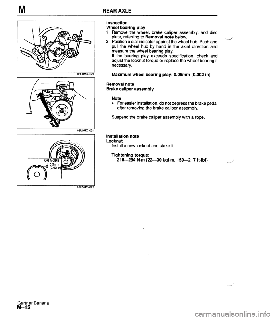
M REAR AXLE Inspection Wheel bearing play 1. Remove the wheel, brake caliper assembly, and disc plate, referring to Removal note below. d 2. Position a dial indicator against the wheel hub. Push and pull the wheel hub by hand in the axial direction and measure the wheel bearing play. If the bearing play exceeds specification, check and adjust the locknut torque or replace the wheel bearing if necessary. Maximum wheel bearing play: 0.05mm (0.002 in) Removal note Brake caliper assembly Note For easier installation, do not depress the brake pedal after removing the brake caliper assembly. Suspend the brake caliper assembly with a rope. Installation note Locknut Install a new locknut and stake it. Tightening torque: 21 6-294 N-m {22-30 kgf-m, 159-217 ft4bf) Gartner Banana
Page 602 of 1708

DRIVE SHAFT M DRIVE SHAFT b '1. Rear wheel 3. Drive shaft 2. Locknut Inspection ................. page M-17 Installation Note ........... page M-18 Removal Note ............. page M-17 Installation Note ........... page M-18 Overhaul .................. page M-19 lnspection 1 Drive shaft 1. Check the dust boot on the drive shaft for cracks, dam- age, leaking grease, and a loose boot band. 2. Check the drive shaft for bending, cracks, and wear of joints and splines. 3. Repair or replace the drive shaft if necessary. I I 45UOMX-024 Removal note Drive shaft Before removing the drive shaft, mark the drive shaft and output shaft for proper installation. 'L/ 25UOMX-012 Gartner Banana
Page 603 of 1708

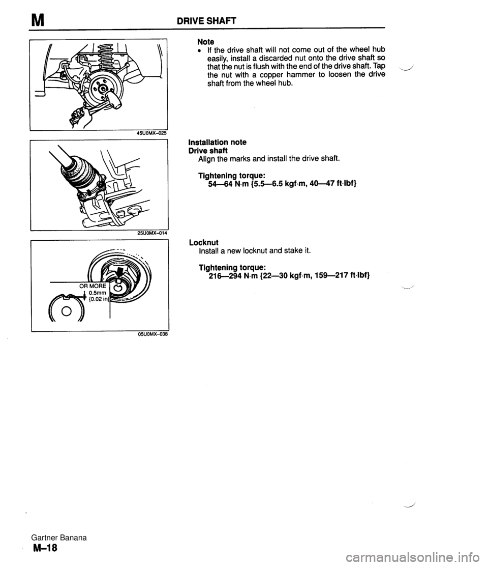
M DRIVE SHAFT Note If the drive shaft will not come out of the wheel hub easily, install a discarded nut onto the drive shaft so that the nut is flush with the end of the drive shaft. Tap _i the nut with a copper hammer to loosen the drive shaft from the wheel hub. Installation note Drive shaft Align the marks and install the drive shaft. Tightening torque: 54-64 N.m (55-6.5 kgf.m, 40--47 ftlbf) Locknut Install a new locknut and stake it. Tightening torque: 21 6-294 N-m (22-30 kgf.m, 159-217 ft4bf) Gartner Banana
Page 605 of 1708

M DRIVE SHAFT Disassembly note Boot bands To remove the boot bands, pry up the locking clip with a screwdriver, then raise the end of the band. d Clip 1. Mark the drive shaft and outer ring with paint as shown. 2. Remove the clip. Snap ring 1. Mark the drive shaft end and inner ring with paint as shown. 2. Remove the snap ring with snap ring pliers. Cage, inner ring, and balls Disassemble in the following order: 1. Insert a screwdriver between the inner ring and cage to remove the balls. 2. Mark the inner ring and cage with paint. 3. Turn the cage approximately 30°, then pull it away from the inner ring. Gartner Banana
Page 607 of 1708

M DRIVE SHAFT 5. Align the marks, then install a new clip. Boot bands 1. Set the boots onto the rings. 2. Release any trapped air from the boots by carefully lifting up the small end of each boot with a cloth-wrapped screwdriver. 3. Verify that the boots are not dented or twisted. 4. Measure the drive shaft length. Standard length: 623.7--658.8mm (24.556-25-936 in) 5. If not within specification, return to step 1. J Standard length (On-vehicle): 640.6mm (25,220 in) 6. Fold the new band back by pulling on the end of it with pliers. The band should be folded in the direction oppo- site the forward revolving direction of the drive shaft. 7. Lock the end of the band by bending the locking clips. Gartner Banana
Page 608 of 1708

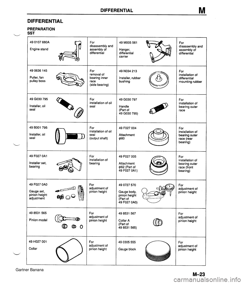
DIFFERENTIAL M DIFFERENTIAL PREPARATION u SST 49 01 07 680A Engine stand For disassembly and assembly of differential 49 MOO5 561 Hanger, differential carrier For disassembly and assembly of differential For removal of bearing inner race (side bearing) 49 NO34 21 3 Installer, rubber bushing For installation of differential mounting rubber - --.. - Puller, fan pulley boss 49 GO30 795 Installer, oil seal For installation of oil seal For installation of bearing outer race Handle (Part of 49 GO30 795) 49 BOO1 795 Installer, oil seal For installation of oil seal (output shaft) 49 F027 004 Attachment $80 For installation of bearing outer race (rear bearing) 49 F027 OAl For installation of bearing 49 F027 005 Attachment $I62 (Part of 49 F027 OAl ) For installation of bearing outer race (front bearing) Installer set, bearing 49 F027 OAO Gauge set, pinion height adjustment 49 0727 570 Gauge body, pinion height (Part of For adjustment of pinion height For adjustment of pinion height 49 F027 OAO) For adjustment of pinion height For adjustment of oinion height Pinion model @==@ Collar A (Part of 49 8531 565) For adjustment of oinion height adjustment of )inion height Gauge block Gartner Banana
Page 613 of 1708

M DIFFERENTIAL SLEEVE BLOCK BOLT (MI 4 x 1.5) dl Removal note Power plant frame (PPF) 1. Disconnect the wire harness from the PPF. 2. Support the transmission with a jack. 3. Remove the power plant frame bracket. (Manual trans- mission) 4. Remove the differential-side bolts, and pry out the spacer. 5. Remove the differential mounting spacer. 6. Turn a bolt (MI4 x 1.5) into the sleeve. 7. Twist and pull the bolt downward. 8. Install a bolt (M6 x 1) into the hole in the block to hold the sleeve, and remove the long bolt (MI4 x 1.5). 9. Remove the bolt ,(M6 x 1). Gartner Banana
Page 614 of 1708

DIFFERENTIAL M t- 900mm (35.43 in) 10. Remove the transmission-side bolts, and remove the PPF. Do not remove the spacers from the PPF. If they are removed, replace the PPF as an assembly. Drive shaft Mark the drive shaft and output shaft for proper installa- tion. Differential 1. Support the differential with a jack. 2. Lower the differential and move it forward. Note If the drive shaft will not separate easily from the out- put shaft, remove a bolt and nut from one side of the upper arm. 3. Separate the driveshaft from the output shaft. 4. To prevent damaging the fire wall, crank angle sensor, and engine mount, support the transmission as follows. (1) Prepare a steel plate (as shown in the figure), a wooden block, bolts (M8 x 1.25), and washers. (2) Install the parts as shown in the figure. Gartner Banana