torque MAZDA PROTEGE 1992 Workshop Manual
[x] Cancel search | Manufacturer: MAZDA, Model Year: 1992, Model line: PROTEGE, Model: MAZDA PROTEGE 1992Pages: 1164, PDF Size: 81.9 MB
Page 434 of 1164
F CONTROL SYSTEM
23UOFX-l! 51
.
r---- - --------1
I
I
i I
I
:,
m7 I
- - -.-
Fc E, Vc Ez 23UOFX-158
WATER THER@OSENSOA
I
03UOFX-21
REPLACE WASHEF
f
OYJOFX-2’
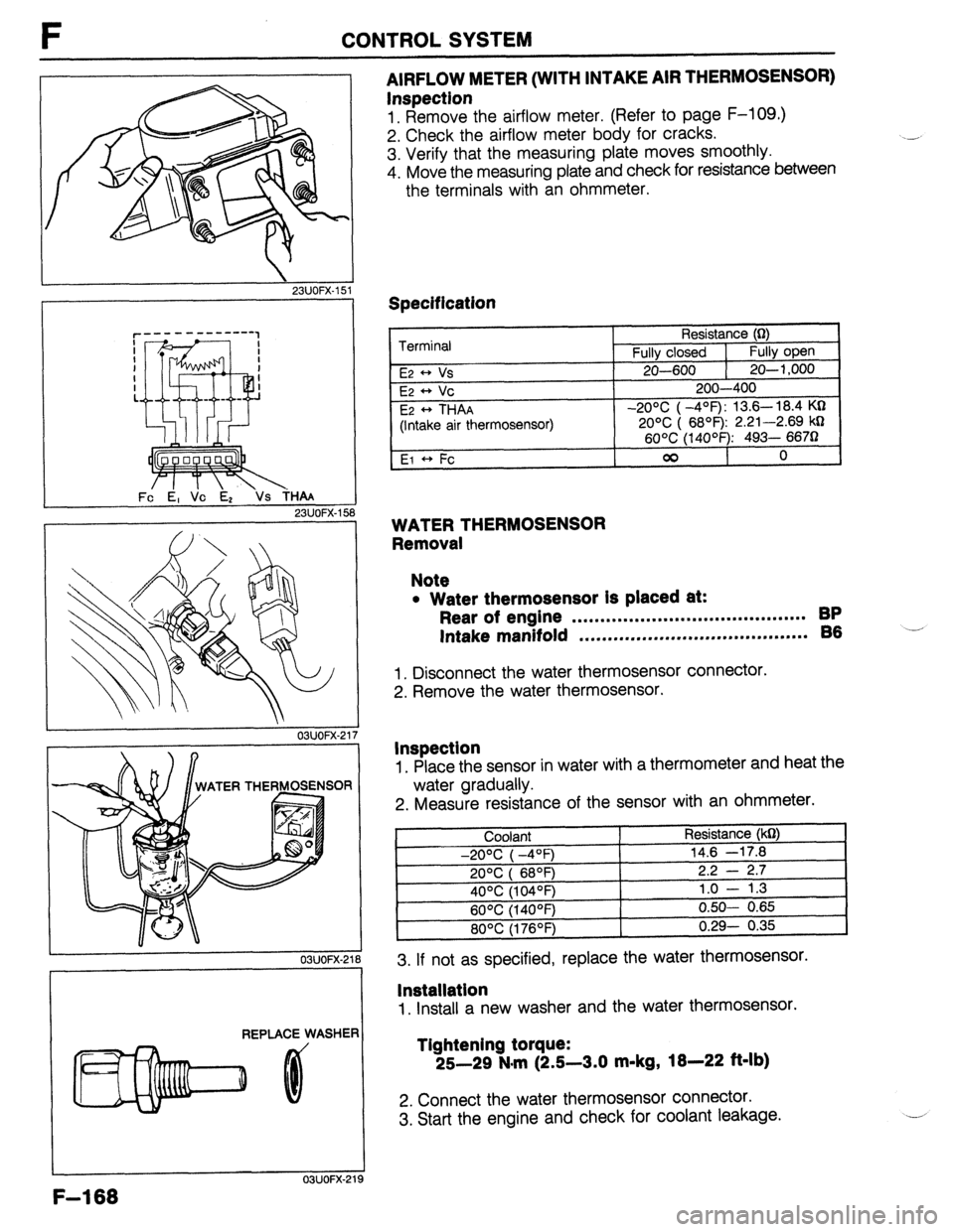
AIRFLOW METER (WITH INTAKE AIR THERMOSENSOR)
Inspection
1. Remove the airflow meter. (Refer to page F-109.)
2. Check the airflow meter body for cracks.
3. Verify that the measuring plate moves smoothly.
4. Move the measuring plate and check for resistance between
the terminals with an ohmmeter.
Specification
Terminal
E2 * Vs
E2 ++ Vc
E2
* THAA
(Intake air thermosensor)
El +, Fc Resistance (0)
Fully closed 1
Fully open
20-600 1 20-l ,000
200-400
-20% ( -4’=F): 13.6- 18.4 KQ
20% ( 6899 2.21-2.69 kD
60°C (14OOF): 493- 6670
00
0
WATER THERMOSENSOR
Removal
Note
l Water thermosensor Is placed at:
Rear of engine . . . . . . . . . . . . . . . . . . . . . . . . ..*.............. BP
Intake manifold ,.*......,..m...,..,.....*....*......... 86 -’
1. Disconnect the water thermosensor connector.
2. Remove the water thermosensor.
Inspection
1. Place the sensor in water with a thermometer and heat the
water gradually.
2. Measure resistance of the sensor with an ohmmeter.
3. If not as specified, replace the water thermosensor.
lnstallatlon
1. Install a new washer and the water thermosensor.
Tlghtening torque:
25-29 N.m (2.5-3.0 m-kg,
18-22 ft-lb)
2. Connect the water thermosensor connector.
3. Start the engine and check for coolant leakage.
F-l 68
Page 437 of 1164
CONTROL SYSTEM F
03UOFX-227
03UOFX-22:
03UOFX-22!
*
03UOFX-231
I
SELF-W CtECXER
WOFX-15
Replacement
1. Disconnect the throttle sensor connector.
2. Remove the throttle sensor mounting screws.
3. Remove the throttle sensor.
4. Install in the reverse order of removal.
Tightening torque:
1.6-2.4 N-m (16-24 cm-kg, 14-21 in-lb)
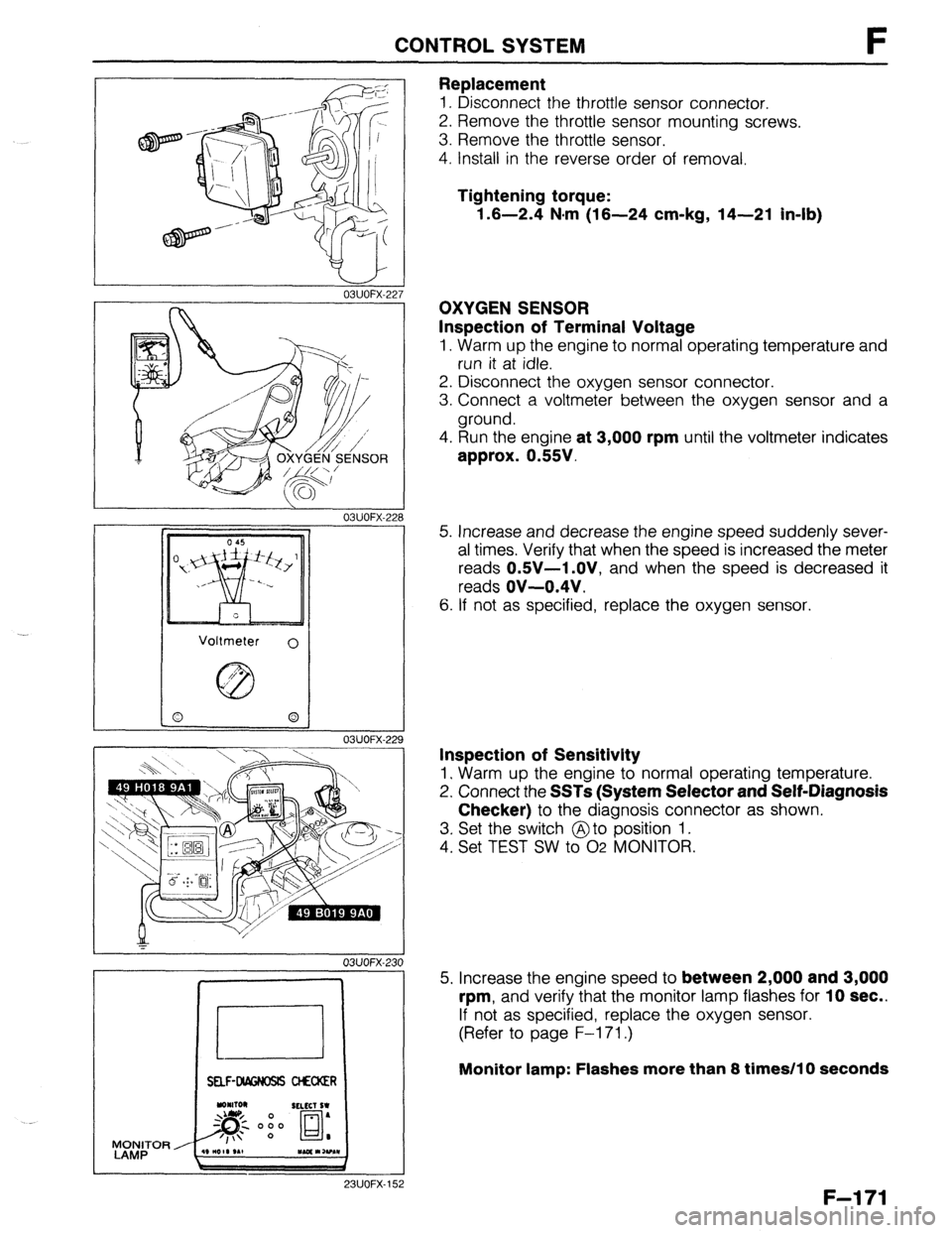
OXYGEN SENSOR
Inspection of Terminal Voltage
1. Warm up the engine to normal operating temperature and
run it at idle.
2. Disconnect the oxygen sensor connector.
3. Connect a voltmeter between the oxygen sensor and a
ground.
4. Run the engine
at 3,000 rpm until the voltmeter indicates
approx. 0.55V.
5. Increase and decrease the engine speed suddenly sever-
al times. Verify that when the speed is increased the meter
reads
OSV-1 .OV, and when the speed is decreased it
reads
OV-0.4V.
6. If not as specified, replace the oxygen sensor.
Inspection of Sensitivity
1. Warm up the engine to normal operating temperature.
2. Connect the
SSTs (System Selector and Self-Diagnosis
Checker)
to the diagnosis connector as shown.
3. Set the switch @to position 1.
4. Set TEST SW to 02 MONITOR.
5. Increase the engine speed to
between 2,000 and 3,000
rpm,
and verify that the monitor lamp flashes for 10 sec..
If not as specified, replace the oxygen sensor.
(Refer to page F-l 71.)
Monitor lamp: Flashes more than 8 times/l 0 seconds
F-l 71
Page 438 of 1164
F CONTROL SYSTEM
23UOFX-15
23UOFX-15
23UOFX-15
LOCK
4
I
13UOFX-oc
F-l 72
6. Turn the ignition switch OFF.
7. Disconnect the negative battery terminal for
at least 20 sec.
to eliminate the malfunction code that was created during
inspection from the control unit memory.
Replacetnent
1. Disconnect the oxygen sensor connector.
2. Remove the oxygen sensor.
3. Install in the reverse order of removal.
Tightening torque:
29-49 N-m (3-5 m-kg, 22-36 ft-lb)
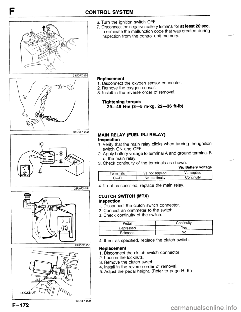
MAIN RELAY (FUEL INJ RELAY)
Inspection
1. Verify that the main relay clicks when turning the ignition
switch ON and OFF.
2. Apply battery voltage to terminal A and ground terminal E3
of the main relay.
3. Check continuity of the terminals as shown.
VB: Battery voltage
Terminals 1 Ve not applied VB applied
C-D No continuity Continuity
4. If not as specified, replace the main relay.
CLUTCH SWITCH (MTX)
Inspection
1, Disconnect the clutch switch connector.
2. Connect an ohmmeter to the switch.
3. Check continuity of the switch.
Pedal Continuity
Depressed Yes
Released No
4. If not as specified, replace the clutch switch. ,
Replacement
1. Disconnect the clutch switch connector.
2. Loosen the locknuts.
3. Remove the clutch switch.
4. Install in the reverse order of removal.
5. Adjust the pedal height. (Refer to page H-6.)
Page 454 of 1164
G CHARGING SYSTEM
WATER PUMP 13UOGX-00,
03UOGX-03:
I /I I III
I f 03UOGX-03:
03UOGX-034
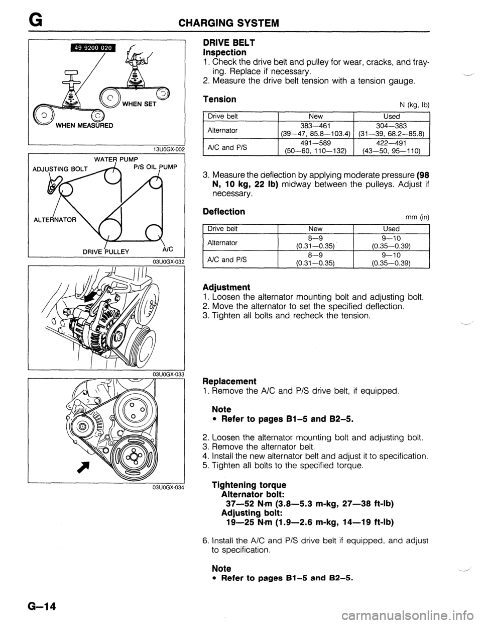
DRIVE BELT
Inspection
1. Check the drive belt and pulley for wear, cracks, and fray-
ing. Replace if necessary.
2. Measure the drive belt tension with a tension gauge. .-A
Tension N (kg, lb)
Drive belt
Alternator
A/C and P/S New Used
383-461
304-303
(39-47, 85.8-103.4) (31-39, 68.2-85.8)
491-589 422-491
(50-60, 11 O-l 32) (43-50, 95-110)
3. Measure the deflection by applying moderate pressure (98
N, 10
kg, 22 lb) midway between the pulleys. Adjust if
necessary.
Deflection mm (in)
Drive belt
Alternator
AIC and P/S New Used
8-9 9-10
(0.31-0.35) (0.35-0.39)
8-9 9-10
(0.31-0.35) (0.35-0.39)
Adjustment
1. Loosen the alternator mounting bolt and adjusting bolt.
2. Move the alternator to set the specified deflection.
3. Tighten all bolts and recheck the tension.
Replacement
1. Remove the A/C and P/S drive belt, if equipped.
Note
l Refer to pages 61-5 and 82-5.
2. Loosen the alternator mounting bolt and adjusting bolt.
3. Remove the alternator belt.
4. Install the new alternator belt and adjust it to specification.
5. Tighten all bolts to the specified torque.
Tightening torque
Alternator bolt:
37-52 N#rn (3.8-5.3 m-kg, 27-38 ft-lb)
Adjusting bolt:
19-25 N-m (1.9-2.6 m-kg, 14-19 ft-lb)
6. Install the A/C and P/S drive belt if equipped, and adjust
to specification.
Note
l Refer to pages 61-5 and 82-5.
G-14
Page 457 of 1164
IGNITION SYSTEM G
r
03UOGX-03
SOHC
LOCK BOLTS
DOHC
A LOCK BOLTS I 03UOGX-0’
03UOGX-C
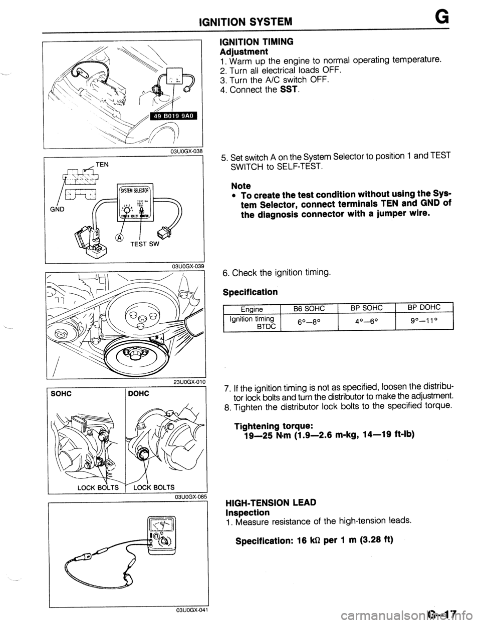
IGNITION TIMING
Adjustment
1. Warm UD the enaine to normal operating temperature.
2. Turn all ‘electricarloads OFF.
3. Turn the A/C switch OFF.
4. Connect the
SST.
5. Set switch A on the System Selector to position
SWITCH to SELF-TEST. 1 and TEST
Note
l To create the test condition without using the Sys-
tem Selector, connect terminals TEN and GND of
the diagnosis connector with a jumper wlre.
6. Check the ignition timing.
Specification
Engine
Ignition timing
BTDC B6 SOHC BP SOHC
60-8O 4O-6O
BP DOHC
9°-110
7. If the ignition timing is not as specified, loosen the distribu-
tor lock bolts and turn the distributor to make the adjustment.
8. Tighten the distributor lock bolts to the specified torque.
Tightening torque:
19-25 N-m (1.9-2.6 m-kg, 14-19 ft-lb)
HIGH-TENSION LEAD
Inspection
1. Measure resistance of the high-tension leads.
Specification: 16 kg per 1 m (3.26 ft)
G-l 7
Page 458 of 1164
G IGNITION SYSTEM
-.-.. .----___ 03UOGX-042
03UOGX-04
--.---- J
03UOGX-044
WEAR AND CARBON
/
c- -BURNT
PLUG GAP
L--
c
DAMAGE AND
,llllll....*llll,lllf DETERIORATIOF
; -,DAMAGE
03UOGX.04
G-18
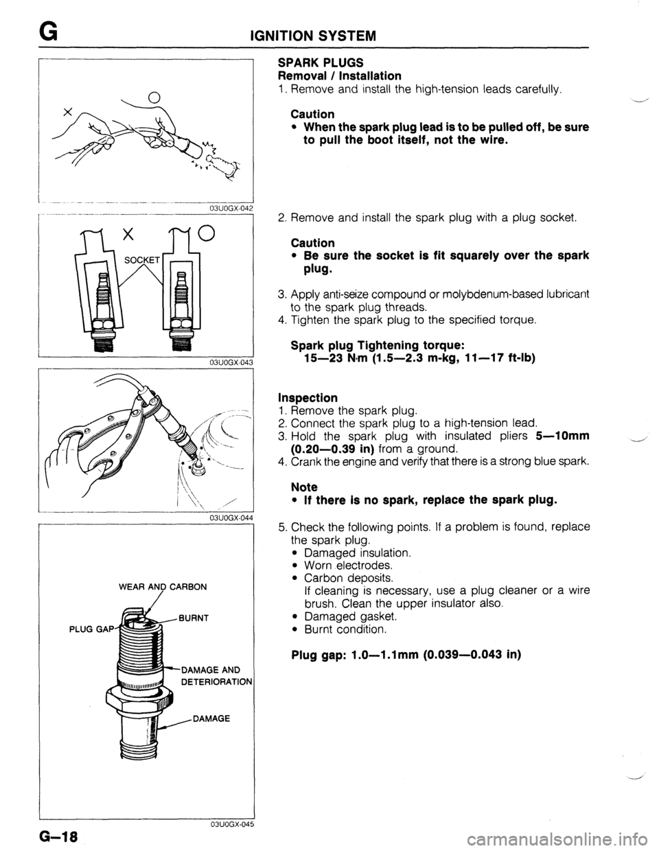
SPARKPLUGS
Removal / Installation
1. Remove and install the high-tension leads carefully.
Caution
l When the spark plug lead is to be pulled off, be sure
to pull the boot itself, not the wire.
Y’
2. Remove and install the spark plug with a plug socket.
Caution
l Be sure the socket is fit squarely over the spark
plug.
3. Apply anti-seize compound or molybdenum-based lubricant
to the spark plug threads.
4. Tighten the spark plug to the specified torque.
Spark plug Tightening torque:
15-23 N.m (1 S-2.3 m-kg, 11-17 f&lb)
Inspection
1. Remove the spark plug.
2. Connect the spark plug to a high-tension lead.
3. Hold the spark plug with insulated pliers
5-10mm
(0.20-0.39 in) from a ground.
4. Crank the engine and verify that there is a strong blue spark.
4
Note
l If there Is no spark, replace the spark plug.
5. Check the following points. If a problem is found, replace
the spark plug.
l Damaged insulation.
l Worn electrodes.
l Carbon deposits.
If cleaning is necessary, use a plug cleaner or a wire
brush. Clean the upper insulator also.
l Damaged gasket.
l Burnt condition.
Plug gap: 1.0-l .l mm (0.039-0.043 in)
Page 476 of 1164
H CLUTCH FLUID
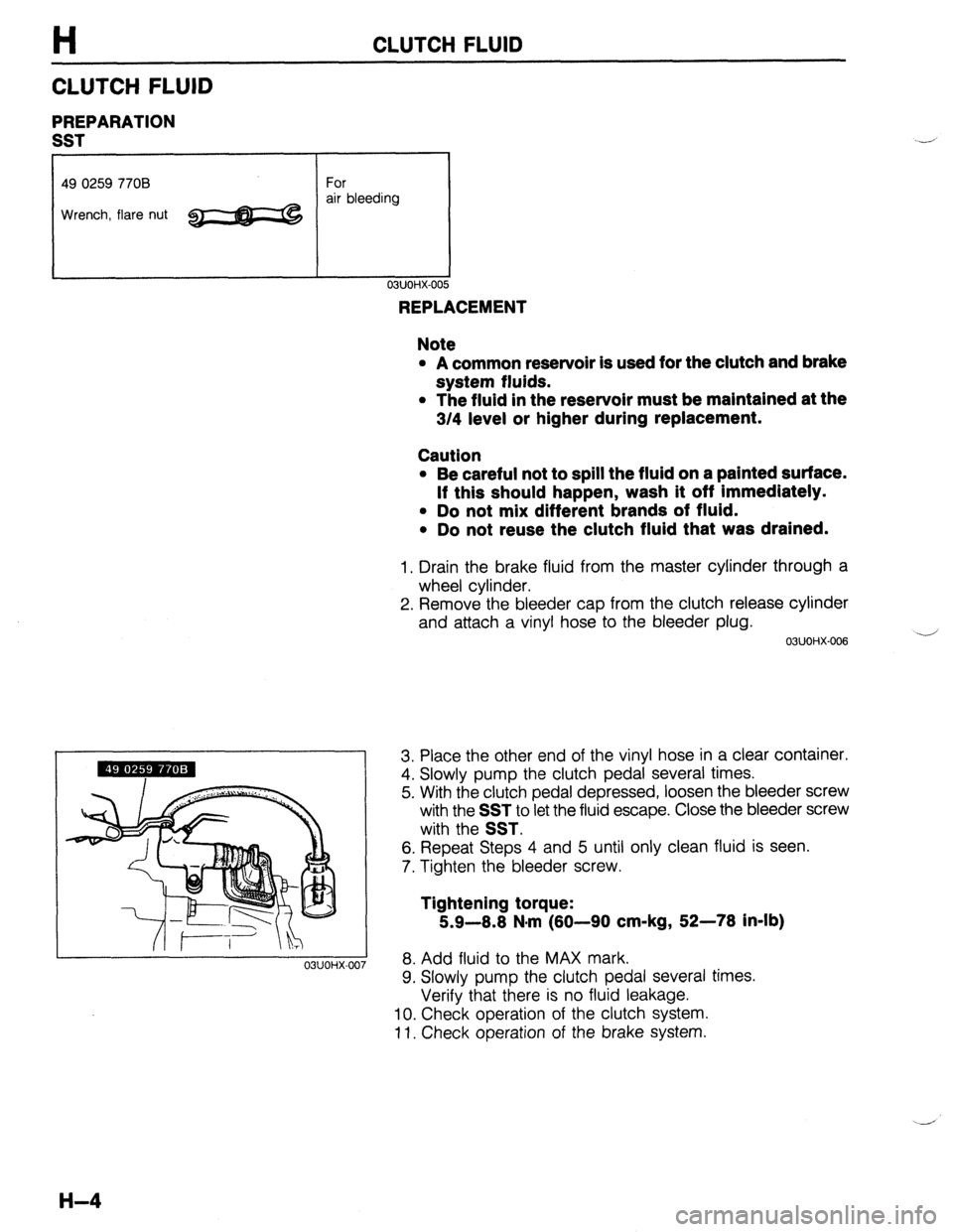
CLUTCH FLUID
PREPARATION
SST
49 0259 7708 For
Wrench, flare nut ~ air bleeding
03UOHX-007
REPLACEMENT
Note
l A common reservoir is used for the clutch and brake
system fluids.
l The fluid in the reservoir must be maintained at the
3/4 level or higher during replacement.
Caution
l Be careful not to spill the fluid on a painted surface.
If this should happen, wash it off Immediately.
l Do not mix different brands of fluid.
l Do not reuse the clutch fluid that was drained.
1. Drain the brake fluid from the master cylinder through a
wheel cylinder.
2. Remove the bleeder cap from the clutch release cylinder
and attach a vinyl hose to the bleeder plug.
03UOHX-006 -
3. Place the other end of the vinyl hose in a clear container.
4. Slowly pump the clutch pedal several times.
5. With the clutch pedal depressed, loosen the bleeder screw
with the
SST to let the fluid escape. Close the bleeder screw
with the
SST.
6. Repeat Steps 4 and 5 until only clean fluid is seen.
7. Tighten the bleeder screw.
Tightening torque:
5.9-8.8 N.m (80-90 cm-kg, 52-78 in-lb)
8. Add fluid to the MAX mark.
9. Slowly pump the clutch pedal several times.
Verify that there is no fluid leakage.
10. Check operation of the clutch system.
11. Check operation of the brake system.
H-4
Page 477 of 1164
CLUTCH PEDAL H
@ 14-19
(1.4-1.9, 10-13)
N.m (m-kg, R-lb)
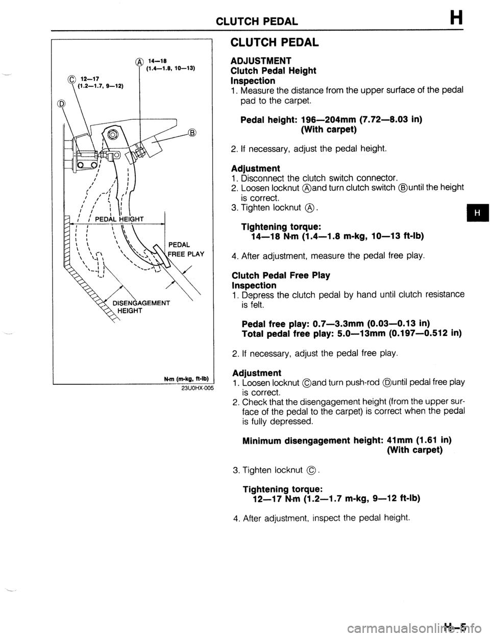
CLUTCH PEDAL
ADJUSTMENT
Clutch Pedal Height
Inspection
1. Measure the distance from the upper surface of the pedal
pad to the carpet.
Pedal height: 196-204mm (7.72-6.03 in)
(With carpet)
2. If necessary, adjust the pedal height.
Adjustment
1. Disconnect the clutch switch connector.
2. Loosen locknut @and turn clutch switch @until the height
is correct.
3. Tighten locknut @ .
Tightening torque:
14-16 N*m (1.4-1.6 m-kg, IO-13 f&lb)
4. After adjustment, measure the pedal free play.
Clutch Pedal Free Play
Inspection
1. Depress the clutch pedal by hand until clutch resistance
is felt.
Pedal free play: 0.7-3.3mm (0.03-0.13 in)
Total pedal free play: 5.0-13mm (0.197-0.512 in)
2. If necessary, adjust the pedal free play.
Adjustment
1. Loosen locknut Oand turn push-rod @until pedal free play
is correct.
2. Check that the disengagement height (from the upper sur-
face of the pedal to the carpet) is correct when the pedal
is fully depressed. 23UOHX-OC
Minimum disengagement height: 41 mm (1.61 in)
(With carpet)
3. Tighten locknut 0.
Tightening torque:
12-17 N-m (1.2-I .7 m-kg, 9-12 ft-lb)
4. After adjustment, inspect the pedal height.
H-5
Page 480 of 1164
H CLUTCH MASTER CYLINDER
23UOHX-Ot ,a
\ I 03UOHX-016
7
I
03UOHX-014
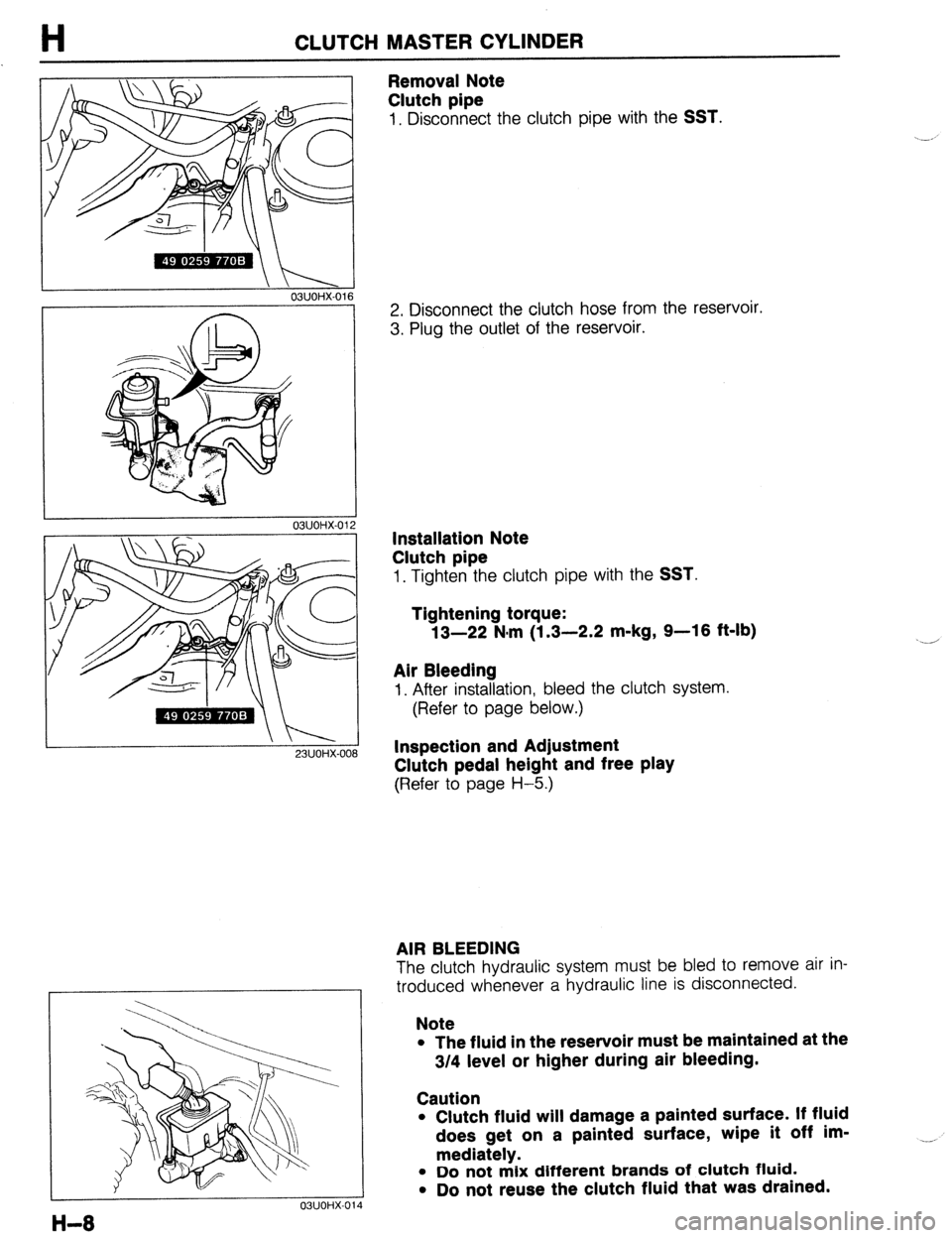
Removal Note
Clutch pipe
1, Disconnect the clutch pipe with the SST.
2. Disconnect the clutch hose from the reservoir.
3. Plug the outlet of the reservoir.
Installation Note
Clutch pipe
1. Tighten the clutch pipe with the SST.
Tightening torque:
13-22 N.m (1.3-2.2 m-kg, 9-16 ft-lb)
Air Bleeding
I. After installation, bleed the clutch system.
(Refer to page below.)
Inspection and Adjustment
Clutch pedal height and free play
(Refer to page H-5.)
AIR BLEEDING
The clutch hydraulic system must be bled to remove air in-
troduced whenever a hydraulic line is disconnected.
Note
l The fluid in the reservoir must be maintained at the
3/4 level or higher during air bleeding.
Caution
l Clutch fluid will damage a painted surface. If fluid
does get on a painted surface, wipe it off im-
mediately.
l Do not mix different brands of clutch fluid.
l Do not reuse the clutch fluid that was drained. __,
Page 481 of 1164
CLUTCH MASTER CYLINDER H
/I f-------i- OWOHX-01
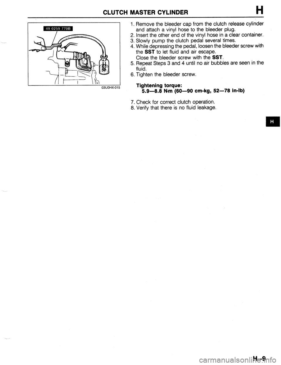
1. Remove the bleeder cap from the clutch release cylinder
and attach a vinyl hose to the bleeder plug.
2. Insert the other end of the vinyl hose in a clear container.
3. Slowly pump the clutch pedal several times.
4. While depressing the pedal, loosen the bleeder screw with
the
SST to let fluid and air escape.
Close the bleeder screw with the
SST.
5. Repeat Steps 3 and 4 until no air bubbles are seen in the
fluid.
6. Tighten the bleeder screw.
Tightening torque:
5.9-8.8 N#rn (80-90 cm-kg, 52-78 in-lb)
7. Check for correct clutch operation.
8. Verify that there is no fluid leakage.
H-9