lock MAZDA PROTEGE 1992 Workshop Manual
[x] Cancel search | Manufacturer: MAZDA, Model Year: 1992, Model line: PROTEGE, Model: MAZDA PROTEGE 1992Pages: 1164, PDF Size: 81.9 MB
Page 857 of 1164
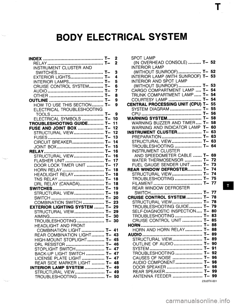
BODY ELECTRICAL SYSTEM
INDEX .......................................... T- 2
RELAY ....................................... T- 2
INSTRUMENT CLUSTER AND
SWITCHES ................................ T- 3
EXTERIOR LIGHTS.. ..................... T- 4
INTERIOR LAMPS.. ...................... T- 5
CRUISE CONTROL SYSTEM.. ........ T- 6
AUDIO ....................................... T- 7
OTHER ...................................... T- 8
OUTLINE ...................................... T- 9
HOW TO USE THIS SECTION.. ...... T- 9
ELECTRICAL TROUBLESHOOTING
TOOLS .....................................
ELECTRICAL SYMBOLS - ............... T- 1x
TROUBLESHOOTING GUIDE.. .........
T- 11
FUSE AND JOINT BOX ..................
T- 12
STRUCTURAL VIEW.. ...................
T- 12
FUSES ....................................... T- 13
CIRCUIT BREAKER.. ....................
T- 14
JOINT BOX ................................. T- 15
RELAY .......................................... T- 16
STRUCTURAL VIEW.. ...................
T- 16
.-
FLASHER UNIT ........................... T- 17
DOOR LOCK TIMER UNIT ............
T- 17
HORN RELAY ............................. T- 18
HEADLIGHT RELAY.. ................... T- 18
TNS RELAY ................................ T- 18
DRL RELAY (CANADA). ................ T- 18
SWITCHES .................................... T- 19
STRUCTURAL VIEW.. ................... T- 19
SWITCH ..................................... T- 20
COMBINATION SWITCH ...............
T- 23
EXTERIOR LIGHTING SYSTEM ....... T- 29
STRUCTURAL VIEW.. ...................
T- 29
AIMING ...................................... T- 30
TROUBLESHOOTING.. .................
T- 30
HEADLIGHT AND FRONT
COMBINATION LIGHT.. ..............
T- 41
REAR COMBINATION LIGHT.. ....... T- 43
HIGH-MOUNT STOPLIGHT.. .......... T- 45
DRL RESISTOR ........................... T- 46
STOPLIGHT SWITCH.. .................. T- 47
BACK-UP LIGHT SWITCH ............. T- 47
LICENSE PLATE LIGHT.. ..............
T- 47
REAR SIDE MARKER LIGHT ......... T- 48
INTERIOR LAMP SYSTEM ..............
T- 49
STRUCTURAL VIEW.. ...................
T- 49
TROUBLESHOOTING ...................
T- 50 SPOT LAMP
(IN OVERHEAD CONSOLE) ......... T- 52
INTERIOR LAMP
(WITHOUT SUNROOF). ............... T- 52
INTERIOR LAMP (WITH SUNROOF) T- 53
INTERIOR AND SPOT LAMP
(WITHOUT SUNROOF). ............... T- 53
CARGO COMPARTMENT LAMP.. .. T- 54
TRUNK COMPARTMENT LAMP.. ... T- 54
COURTESY LAMP ....................... T- 54
CENTRAL PROCESSING UNIT (CPU) T- 55
SYSTEM DIAGRAM ...................... T- 55
CPU .......................................... T- 56
WARNING SYSTEM.. ...................... T- 58
WARNING BUZZER AND TIMER .... T- 58
WARNING AND INDICATOR LAMP T- 60
INSTRUMENT CLUSTER.. ............... T- 63
PREPARATION ............................ T- 63
STRUCTURAL VIEW ..................... T- 63
TROUBLESHOOTING ................... T- 64
INSTRUMENT CLUSTER
AND SPEEDOMETER CABLE.. .... T- 89
WATER THERMOSENSOR ............ T- 72
FUEL GAUGE SENDER UNIT.. ...... T- 73
REAR WINDOW DEFROSTER.. ........ T- 74
STRUCTURAL VIEW.. ................... T- 74
TROUBLESHOOTING ................... T- 75
FILAMENT .................................. T- 77
REAR WINDOW DEFROSTER
SWITCH .................................... T- 77
CRUISE CONTROL SYSTEM.. ......... T- 78
STRUCTURAL VIEW.. ................... T- 78
TROUBLESHOOTING GUIDE.. ....... T- 79
SELF-DIAGNOSTIC INSPECTION .... T- 80
TROUBLESHOOTING ................... T- 83
CRUISE CONTROL UNIT .............. T- 85
HORN ........................................... T- 88
HORN AND HORN RELAY.. .......... T- 88
AUDIO .......................................... T- 89
STRUCTURAL VIEW.. ................... T- 89
OUTLINE OF AUDIO.. .................. T- 90
SYSTEM ..................................... T- 91
TROUBLESHOOTING ................... T- 92
CAUSES OF NOISE ..................... T- 96
AUDIO COMPONENT.. ................. T- 98
DOOR SPEAKER .........................
REARSPEAKER .......................... ;-
- !3;
ANTENNA FEEDER ..................... T- 99
23UOTX-001
Page 858 of 1164

T INDEX
INDEX
RELAY
ION 8
1. Flasher unit
Inspection . . . . . . . . . . . . . . . . . . . . . . . . . . . . . . . . . . .
page T-i 7
2. Door lock timer unit
Inspection . . . . . . . . . . . . . . . . . ..l.........I..... page T-l 7
3. Horn relay
Inspection . . . . . . . . . . . . . . . . . . . . . . . . . . . . . . . . . . .
page T-l 8
4. DRL control unit (Canada)
Troubleshooting . . . . . . . . . . . . . . . . . . . . . . . . . .
page T-33
T-2
13UOTX-00:
5. DRL relay (Canada)
inspection . . . . . . . . . . . . . . . . . . . . . . . . . . . . . . . . . . .
page T-l 8
6. TNS relay
Inspection
. . . . . . . . . . . . . . . . . . . . . . . . . . . . . . . . . . . page T-l 8
7. Headlight relay
Inspection
. . . . . . . . . . . . . . . . . . . . . . . . . . . . . . . . . . . page T-l 8
Page 869 of 1164
FUSE AND JOINT BOX
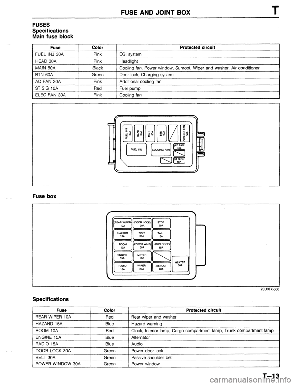
FUSES
Specifications
Main fuse block
Fuse Color
FUEL INJ 30A Pink
HEAD 30A Pink
MAIN 80A Black
BTN 60A Green
AD FAN 30A Pink
ST SIG 10A Red
ELEC FAN 30A Pink Protected circuit
EGI system
Headlight
Cooling fan, Power window, Sunroof, Wiper and washer, Air conditioner
Door lock, Charging system
Additional cooling fan
Fuel pump
Cooling fan
Fuse box
23UOTX-001
Specifications
Fuse
REAR WIPER 10A
HAZARD 15A
ROOM IOA
ENGINE 15A
RADIO 15A
DOOR LOCK 30A
BELT 30A
POWER WINDOW 30A Color
Red
Blue
Red
Blue
Blue
Green
Green
Green Protected circuit
Rear wiper and washer
Hazard warning
Clock, interior lamp, Cargo compartment lamp, Trunk compartment lamp
Alternator
Audio
Power door lock
Passive shoulder belt
Power window
1
T-13
Page 872 of 1164

T RELAY
RELAY
STRUCTURAL VIEW
:TION S
1 SUOTX-01:
1. Flasher unit
5. DRL relay (Canada)
Inspection
. . . . . . . . . . . . . . . . . . . . . . . . . . . . . . . . . . .
page
T-l 7 2. Door lock timer unit
inspection
. . . . . . . . . . . . . . . . . . . . . . . . . . . . . , . . . . .
T-l 7
3. Horn relay page
Inspection . . . . . . . . . . . . . . . . . . . . . . . . . . . . . . . . . . .
T-l 8 4.
DRL control unit (Canada) page
Troubleshooting .,..........,..,.......... page T-33 Inspection . . . . . . . . . . . . . . . . . . . . . . . . . . . . . . . . . . .
6. TNS relay page
T-l 8
Inspection .I..............,.................. page T-l 8
7. Headlight relay
Inspection ,,,,....,.,.,......,~~,...~.....,.~ page T-i 8
T-l 6
Page 873 of 1164

RELAY
h f d
OWOTX-01;
OWOTX-01’
23UOTX-00
FLASHER UNIT
Inspection
1. Check for continuity between terminals of the flasher unit.
0: Indicates continuity X: No continuity
Note
l Set the tester to the xl,OOOQ range.
2. If continuity is not as specified, replace the switch.
DOOR LOCK TIMER UNIT
inspection
1. Check for continuity between terminals.
a-h X c-e 0 e-h 0
b-c X c-f 0 f-h X
0: Continuity X: Non-continuity
Note
l Set the tester to x1000Q range.
l Continuity includes the state with resistance, and
Non-continuity means insulated.
2. Connect the battery voltage to the “b” terminal and the
ground to the “a” terminal. Then, short circuit the “h” and
“d” terminals between the “h” and “c” terminals, and check
that the relay clicks.
T-17
Page 895 of 1164

EXTERIOR LIGHTING SYSTEM T
Stoplight
Circuit diaaram
GTOPLIGHTS F-2
SHIFT-LOCK
BLUB TRADE NUMBER
STOPLIGHT: 1157 (27W)
HIGH MOUNT
STOPLIGHT: 921 (18.4W) G (F) *ENGINE CONTROL UNIT
(SECTION B- lc;26)
G (F) *CRUISE CONTROL UNIT
(SECTION 01)
WITH REAR SPOILER
HIGH MOUNl-
STOPLIGHT
STOPLIGHT STOPLIGHT
-06 STOPLIGHT
SWITCH (F) F-07 HIGH MOUNT STOP-E-12 STOPLIGHT LH(R) E-13 STOPLIGHT RH(R)
LIGHT (R3)
WITH
REAR SPOILER---+ (R2)
03UOTX-057
T-39
Page 931 of 1164
REAR WINDOW DEFROSTER T
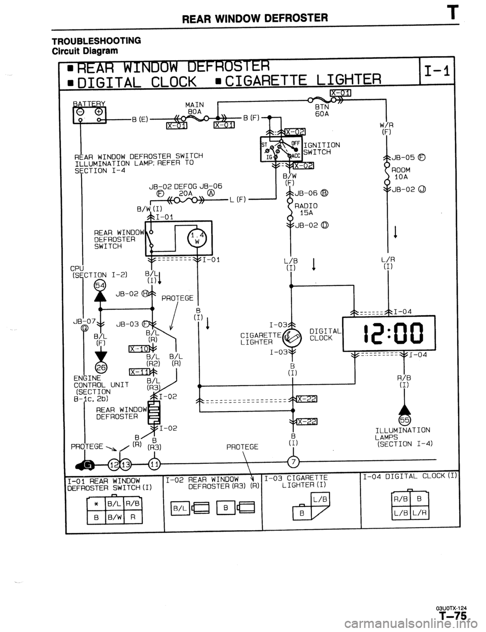
TROUBLESHOOTING
Circuit Diagram
. .-
m DIGITAL CLOCK WXGARETTE LIGHTER I-l
f$pjg
MAIN
BOA BTN
60A v v
0. o! B (E)
l- IX-0 lJ
Ix-u REAR WINDOW DEFROSTER SWITCH TI LUMINATION LAMP: REFER TO JB-05 a
CTION I-4
I nnnt.,4
.L (F)
SE
JB-02LJ:t=;GJB-06
a3 ,, ,, @
I \\- //
B/W (I)
ET?-- (F)
5 JB-06 @
RADIO
15A
JB-02 0
1 ,“Yll IOA
JB-02 0
REAR WINDOW
m&R;~TER I
4 JB-02 @+ PRTEGE i
IV
tr I
I+ LA.“, I I\-1 I
I - -
_--___---
_._- ------
I 2s 1 w
rzlznl+ I I (3
I I -. .--. .- tNGlNt CONTROL UNIT
(SECTION
B-;c. 2b)
REAR WINDOW
DEFROSTER
PRO,TEGE ,/ ILLUMINATION
LAMPS
(SECTION I-4)
‘-01
REAR WINDOW I-02 REAR WINDOW I-03 CIGARETTE
jEFROSTER SWITCH (1)
* B/L R/B
B B/W R
03UOTX-124
T-75
Page 974 of 1164
U TROU6LESHOOTlNG GUIDE
Case 4 Moisture in system
Measured pressure
Low-pressure: 50 cmHg (2.0 inHg): [Vacuum1
High-pressure: 667-l ,472 kPa (7-15 kg/cm , loo-213 psi)
Condition
Intermittent cooling
(Moisture in refrigeration system freezes in expansion valve and causes temporary blocking.
After time, ice melts and condition returns to normal.)
SMUOUX-088
CAUSE ACTION
7 r
MOISTURE
IN SYSTEM WW;MTE
-
23uoux-O!
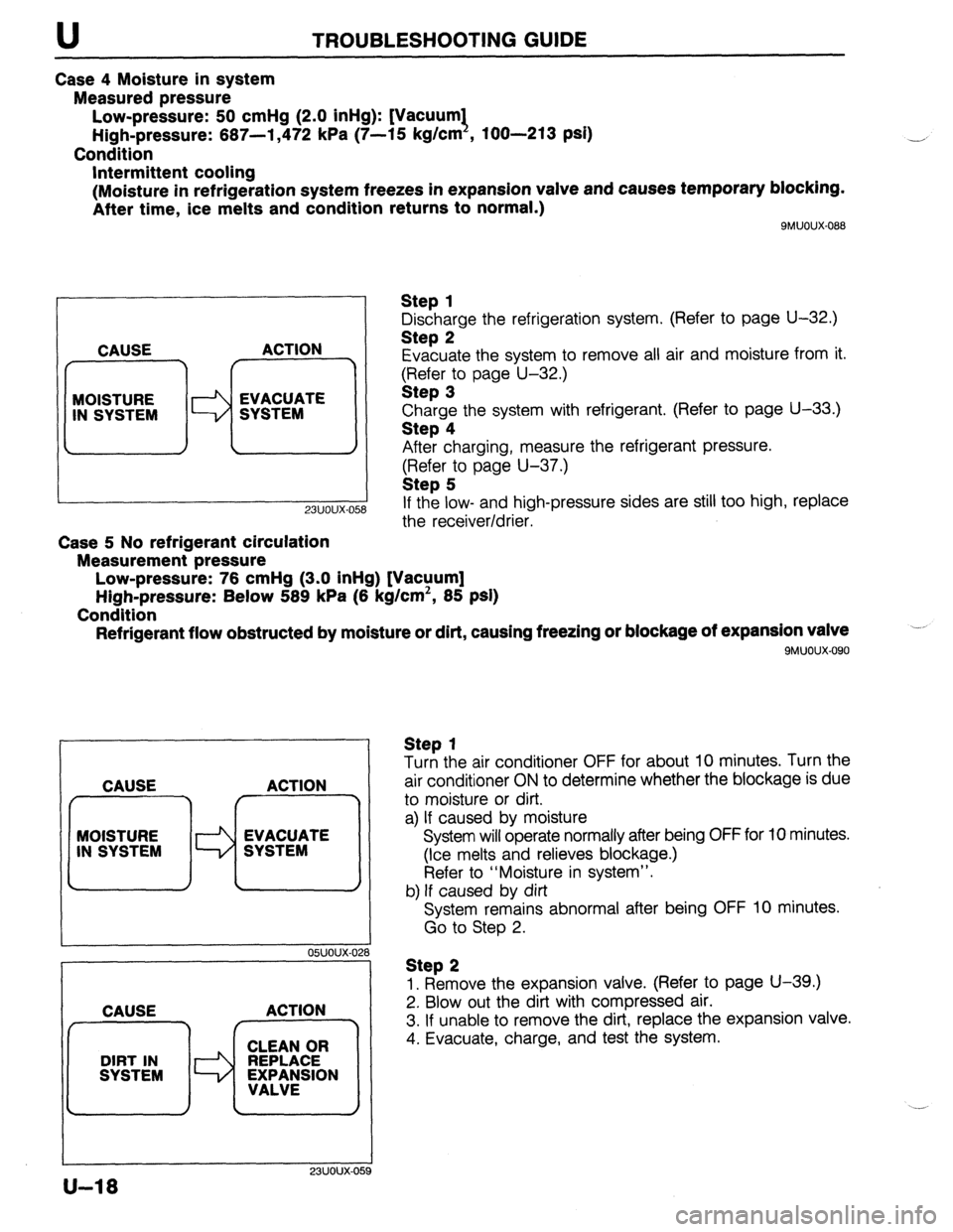
Case 5 No refrigerant circulation
Measurement pressure
Low-pressure: 76 cmHg (3.0 inHg) [Vacuum]
High-pressure: Below 589 kPa (6 kg/cm’, 85 psi)
Condition
Refrigerant flow obstructed by moisture or dirt, causing freezing or blockage of expansion valve
9MUOUX.090
Step 1
Discharge the refrigeration system, (Refer to page U-32.)
Step 2
Evacuate the system to remove all air and moisture from it.
$?&$r:o page U-32.)
Charge the system with refrigerant. (Refer to page U-33.)
Step 4
After charging, measure the refrigerant pressure.
(Refer to page U-37.)
Step 5
If the low- and high-pressure sides are still too high, replace
the receiver/drier.
CAUSE ACTION
f r^‘---7
MOISTURE
Id EVACUATE
IN SYSTEM SYSTEM
I I
05UOUX-02
CAUSE ACTION
23UOUX-OE
Step 1
Turn the air conditioner OFF for about 10 minutes. Turn the
air conditioner ON to determine whether the blockage is due
to moisture or dirt.
a) If caused by moisture
System will operate normally after being OFF for 10 minutes.
(Ice melts and relieves blockage.)
Refer to “Moisture in system”.
b) If caused by dirt
System remains abnormal after being OFF 10 minutes.
Go to Step 2.
Step 2
1. Remove the expansion valve. (Refer to page U-39.)
2. Blow out the dirt with compressed air.
3. If unable to remove the dirt, replace the expansion valve.
4. Evacuate, charge, and test the system.
U-18
Page 977 of 1164
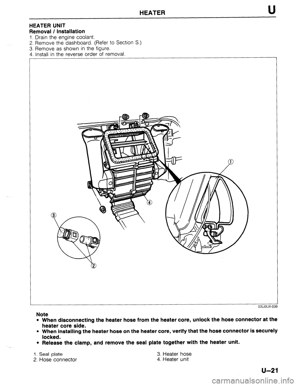
HEATER U
HEATER UNIT
Removal / Installation
1. Drain the engine coolant.
2. Remove the dashboard. (Refer to Section S.)
3. Remove as shown in the figure.
4. Install in the reverse order of removal
Note
l When disconnecting the heater hose from the heater core, unlock the hose connector at the
heater core side.
l When installing the heater hose on the heater core, verify that the hose connector is securely
locked.
l Release the clamp, and remove the seal plate together with the heater unit.
1. Seal plate 3. Heater hose
2. Hose connector
4. Heater unit
u-21
Page 987 of 1164

AIR CONDITIONER U
REFRIGERANT SYSTEM
Safety Precaution
1. R-12 liquid refrigerant is highly volatile. A drop of it on the
skin could result in localized frostbite. When handling the
refrigerant, be sure to wear gloves.
2. If the refrigerant splashes into the eyes, wash them with clean
water immediately. Always wear goggles or glasses to pro-
tect the eyes.
9MUOUX-125 3. The R-12 container is a highly pressurized vessel.
Never subject it to high heat, and be sure that the temper-
ature where it is stored is below 52OC
(125.6OF).
4. A halide leak detector is often used to check the system
for refrigerant leakage. R-l 2, upon coming into contact with
the flame, produces phosgene, a toxic gas. Always provide
adequate ventilation.
o3uoux-11 4
9MUOUX-12
Refrigerant System Service Basics
Refrigerant container service valve
1. Turn the handle fully counterclockwise before connecting
the valve to the refrigerant container.
2. Turn the outlet valve counterclockwise until it reaches its
highest position.
3. Turn the outlet valve fully clockwise by hand. Connect the
center hose to the valve fitting.
4. Turn the handle clockwise to puncture the sealed can.
5. Turn the handle fully counterclockwise to fill the center hose.
Do not open the high- or low-pressure manual valves.
6. Loosen the hose nut connected to the center fitting of the
manifold gauge. Allow air to escape. Then retighten the nut.
13uoux-012
u-31