MERCEDES-BENZ SPRINTER 2006 Service Manual
Manufacturer: MERCEDES-BENZ, Model Year: 2006, Model line: SPRINTER, Model: MERCEDES-BENZ SPRINTER 2006Pages: 2305, PDF Size: 48.12 MB
Page 2231 of 2305
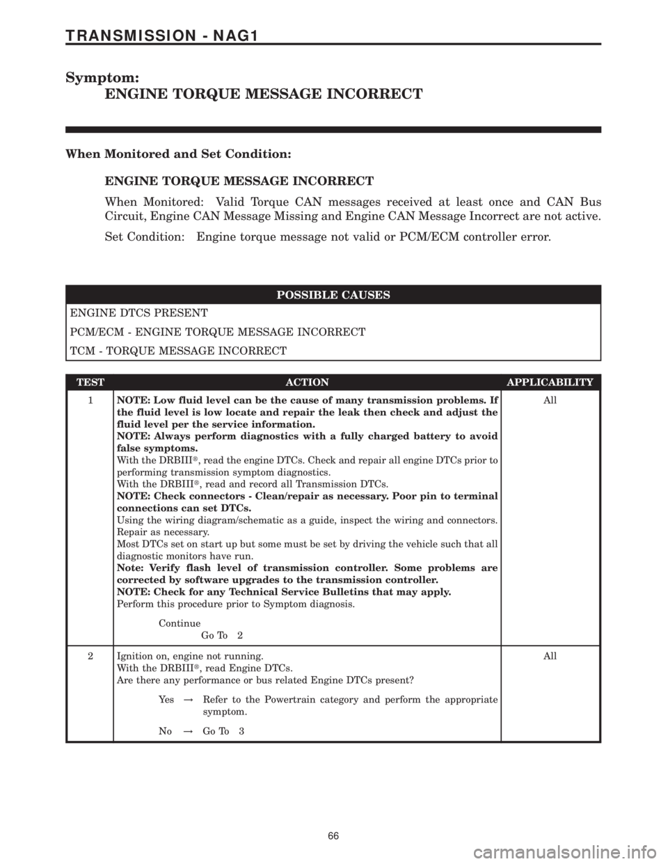
Symptom:
ENGINE TORQUE MESSAGE INCORRECT
When Monitored and Set Condition:
ENGINE TORQUE MESSAGE INCORRECT
When Monitored: Valid Torque CAN messages received at least once and CAN Bus
Circuit, Engine CAN Message Missing and Engine CAN Message Incorrect are not active.
Set Condition: Engine torque message not valid or PCM/ECM controller error.
POSSIBLE CAUSES
ENGINE DTCS PRESENT
PCM/ECM - ENGINE TORQUE MESSAGE INCORRECT
TCM - TORQUE MESSAGE INCORRECT
TEST ACTION APPLICABILITY
1NOTE: Low fluid level can be the cause of many transmission problems. If
the fluid level is low locate and repair the leak then check and adjust the
fluid level per the service information.
NOTE: Always perform diagnostics with a fully charged battery to avoid
false symptoms.
With the DRBIIIt, read the engine DTCs. Check and repair all engine DTCs prior to
performing transmission symptom diagnostics.
With the DRBIIIt, read and record all Transmission DTCs.
NOTE: Check connectors - Clean/repair as necessary. Poor pin to terminal
connections can set DTCs.
Using the wiring diagram/schematic as a guide, inspect the wiring and connectors.
Repair as necessary.
Most DTCs set on start up but some must be set by driving the vehicle such that all
diagnostic monitors have run.
Note: Verify flash level of transmission controller. Some problems are
corrected by software upgrades to the transmission controller.
NOTE: Check for any Technical Service Bulletins that may apply.
Perform this procedure prior to Symptom diagnosis.All
Continue
Go To 2
2 Ignition on, engine not running.
With the DRBIIIt, read Engine DTCs.
Are there any performance or bus related Engine DTCs present?All
Ye s!Refer to the Powertrain category and perform the appropriate
symptom.
No!Go To 3
66
TRANSMISSION - NAG1
Page 2232 of 2305
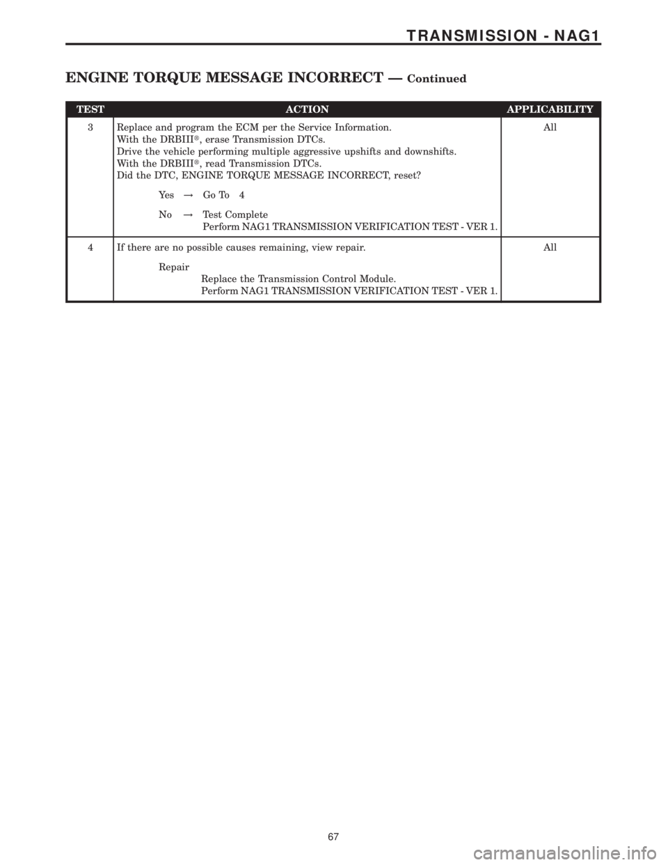
TEST ACTION APPLICABILITY
3 Replace and program the ECM per the Service Information.
With the DRBIIIt, erase Transmission DTCs.
Drive the vehicle performing multiple aggressive upshifts and downshifts.
With the DRBIIIt, read Transmission DTCs.
Did the DTC, ENGINE TORQUE MESSAGE INCORRECT, reset?All
Ye s!Go To 4
No!Test Complete
Perform NAG1 TRANSMISSION VERIFICATION TEST - VER 1.
4 If there are no possible causes remaining, view repair. All
Repair
Replace the Transmission Control Module.
Perform NAG1 TRANSMISSION VERIFICATION TEST - VER 1.
67
TRANSMISSION - NAG1
ENGINE TORQUE MESSAGE INCORRECT ÐContinued
Page 2233 of 2305
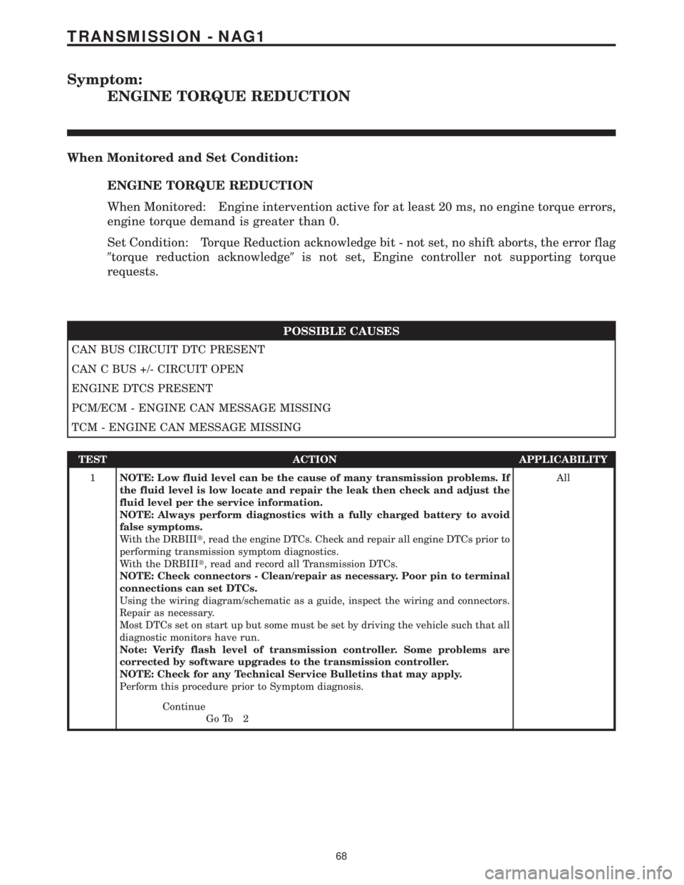
Symptom:
ENGINE TORQUE REDUCTION
When Monitored and Set Condition:
ENGINE TORQUE REDUCTION
When Monitored: Engine intervention active for at least 20 ms, no engine torque errors,
engine torque demand is greater than 0.
Set Condition: Torque Reduction acknowledge bit - not set, no shift aborts, the error flag
9torque reduction acknowledge9is not set, Engine controller not supporting torque
requests.
POSSIBLE CAUSES
CAN BUS CIRCUIT DTC PRESENT
CAN C BUS +/- CIRCUIT OPEN
ENGINE DTCS PRESENT
PCM/ECM - ENGINE CAN MESSAGE MISSING
TCM - ENGINE CAN MESSAGE MISSING
TEST ACTION APPLICABILITY
1NOTE: Low fluid level can be the cause of many transmission problems. If
the fluid level is low locate and repair the leak then check and adjust the
fluid level per the service information.
NOTE: Always perform diagnostics with a fully charged battery to avoid
false symptoms.
With the DRBIIIt, read the engine DTCs. Check and repair all engine DTCs prior to
performing transmission symptom diagnostics.
With the DRBIIIt, read and record all Transmission DTCs.
NOTE: Check connectors - Clean/repair as necessary. Poor pin to terminal
connections can set DTCs.
Using the wiring diagram/schematic as a guide, inspect the wiring and connectors.
Repair as necessary.
Most DTCs set on start up but some must be set by driving the vehicle such that all
diagnostic monitors have run.
Note: Verify flash level of transmission controller. Some problems are
corrected by software upgrades to the transmission controller.
NOTE: Check for any Technical Service Bulletins that may apply.
Perform this procedure prior to Symptom diagnosis.All
Continue
Go To 2
68
TRANSMISSION - NAG1
Page 2234 of 2305
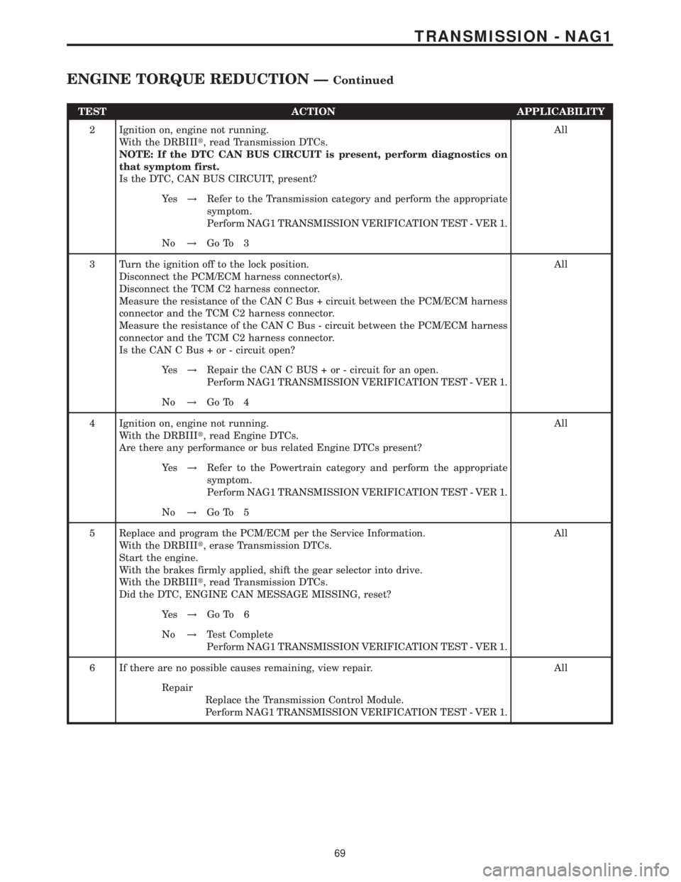
TEST ACTION APPLICABILITY
2 Ignition on, engine not running.
With the DRBIIIt, read Transmission DTCs.
NOTE: If the DTC CAN BUS CIRCUIT is present, perform diagnostics on
that symptom first.
Is the DTC, CAN BUS CIRCUIT, present?All
Ye s!Refer to the Transmission category and perform the appropriate
symptom.
Perform NAG1 TRANSMISSION VERIFICATION TEST - VER 1.
No!Go To 3
3 Turn the ignition off to the lock position.
Disconnect the PCM/ECM harness connector(s).
Disconnect the TCM C2 harness connector.
Measure the resistance of the CAN C Bus + circuit between the PCM/ECM harness
connector and the TCM C2 harness connector.
Measure the resistance of the CAN C Bus - circuit between the PCM/ECM harness
connector and the TCM C2 harness connector.
Is the CAN C Bus + or - circuit open?All
Ye s!Repair the CAN C BUS + or - circuit for an open.
Perform NAG1 TRANSMISSION VERIFICATION TEST - VER 1.
No!Go To 4
4 Ignition on, engine not running.
With the DRBIIIt, read Engine DTCs.
Are there any performance or bus related Engine DTCs present?All
Ye s!Refer to the Powertrain category and perform the appropriate
symptom.
Perform NAG1 TRANSMISSION VERIFICATION TEST - VER 1.
No!Go To 5
5 Replace and program the PCM/ECM per the Service Information.
With the DRBIIIt, erase Transmission DTCs.
Start the engine.
With the brakes firmly applied, shift the gear selector into drive.
With the DRBIIIt, read Transmission DTCs.
Did the DTC, ENGINE CAN MESSAGE MISSING, reset?All
Ye s!Go To 6
No!Test Complete
Perform NAG1 TRANSMISSION VERIFICATION TEST - VER 1.
6 If there are no possible causes remaining, view repair. All
Repair
Replace the Transmission Control Module.
Perform NAG1 TRANSMISSION VERIFICATION TEST - VER 1.
69
TRANSMISSION - NAG1
ENGINE TORQUE REDUCTION ÐContinued
Page 2235 of 2305
Symptom:
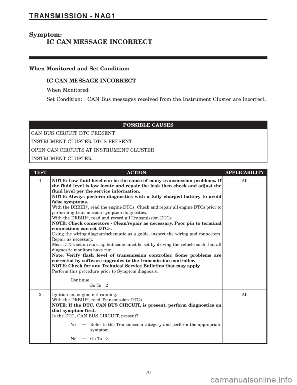
IC CAN MESSAGE INCORRECT
When Monitored and Set Condition:
IC CAN MESSAGE INCORRECT
When Monitored:
Set Condition: CAN Bus messages received from the Instrument Cluster are incorrect.
POSSIBLE CAUSES
CAN BUS CIRCUIT DTC PRESENT
INSTRUMENT CLUSTER DTCS PRESENT
OPEN CAN CIRCUITS AT INSTRUMENT CLUSTER
INSTRUMENT CLUSTER
TEST ACTION APPLICABILITY
1NOTE: Low fluid level can be the cause of many transmission problems. If
the fluid level is low locate and repair the leak then check and adjust the
fluid level per the service information.
NOTE: Always perform diagnostics with a fully charged battery to avoid
false symptoms.
With the DRBIIIt, read the engine DTCs. Check and repair all engine DTCs prior to
performing transmission symptom diagnostics.
With the DRBIIIt, read and record all Transmission DTCs.
NOTE: Check connectors - Clean/repair as necessary. Poor pin to terminal
connections can set DTCs.
Using the wiring diagram/schematic as a guide, inspect the wiring and connectors.
Repair as necessary.
Most DTCs set on start up but some must be set by driving the vehicle such that all
diagnostic monitors have run.
Note: Verify flash level of transmission controller. Some problems are
corrected by software upgrades to the transmission controller.
NOTE: Check for any Technical Service Bulletins that may apply.
Perform this procedure prior to Symptom diagnosis.All
Continue
Go To 2
2 Ignition on, engine not running.
With the DRBIIIt, read Transmission DTCs.
NOTE: If the DTC, CAN BUS CIRCUIT, is present, perform diagnostics on
that symptom first.
Is the DTC, CAN BUS CIRCUIT, present?All
Ye s!Refer to the Transmission category and perform the appropriate
symptom.
No!Go To 3
70
TRANSMISSION - NAG1
Page 2236 of 2305
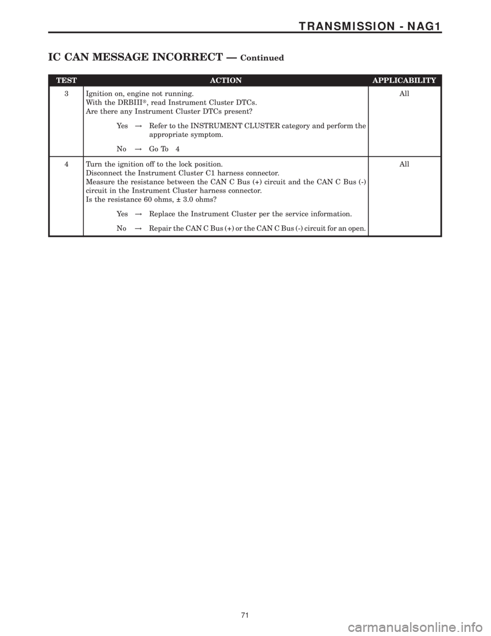
TEST ACTION APPLICABILITY
3 Ignition on, engine not running.
With the DRBIIIt, read Instrument Cluster DTCs.
Are there any Instrument Cluster DTCs present?All
Ye s!Refer to the INSTRUMENT CLUSTER category and perform the
appropriate symptom.
No!Go To 4
4 Turn the ignition off to the lock position.
Disconnect the Instrument Cluster C1 harness connector.
Measure the resistance between the CAN C Bus (+) circuit and the CAN C Bus (-)
circuit in the Instrument Cluster harness connector.
Is the resistance 60 ohms, 3.0 ohms?All
Ye s!Replace the Instrument Cluster per the service information.
No!Repair the CAN C Bus (+) or the CAN C Bus (-) circuit for an open.
71
TRANSMISSION - NAG1
IC CAN MESSAGE INCORRECT ÐContinued
Page 2237 of 2305
Symptom:
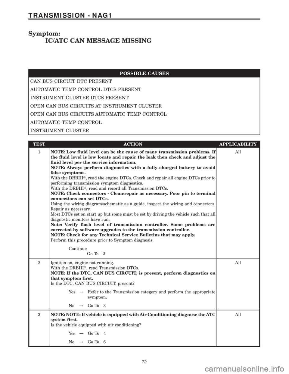
IC/ATC CAN MESSAGE MISSING
POSSIBLE CAUSES
CAN BUS CIRCUIT DTC PRESENT
AUTOMATIC TEMP CONTROL DTCS PRESENT
INSTRUMENT CLUSTER DTCS PRESENT
OPEN CAN BUS CIRCUITS AT INSTRUMENT CLUSTER
OPEN CAN BUS CIRCUITS AUTOMATIC TEMP CONTROL
AUTOMATIC TEMP CONTROL
INSTRUMENT CLUSTER
TEST ACTION APPLICABILITY
1NOTE: Low fluid level can be the cause of many transmission problems. If
the fluid level is low locate and repair the leak then check and adjust the
fluid level per the service information.
NOTE: Always perform diagnostics with a fully charged battery to avoid
false symptoms.
With the DRBIIIt, read the engine DTCs. Check and repair all engine DTCs prior to
performing transmission symptom diagnostics.
With the DRBIIIt, read and record all Transmission DTCs.
NOTE: Check connectors - Clean/repair as necessary. Poor pin to terminal
connections can set DTCs.
Using the wiring diagram/schematic as a guide, inspect the wiring and connectors.
Repair as necessary.
Most DTCs set on start up but some must be set by driving the vehicle such that all
diagnostic monitors have run.
Note: Verify flash level of transmission controller. Some problems are
corrected by software upgrades to the transmission controller.
NOTE: Check for any Technical Service Bulletins that may apply.
Perform this procedure prior to Symptom diagnosis.All
Continue
Go To 2
2 Ignition on, engine not running.
With the DRBIIIt, read Transmission DTCs.
NOTE: If the DTC, CAN BUS CIRCUIT, is present, perform diagnostics on
that symptom first.
Is the DTC, CAN BUS CIRCUIT, present?All
Ye s!Refer to the Transmission category and perform the appropriate
symptom.
No!Go To 3
3NOTE: NOTE: If vehicle is equipped with Air Conditioning diagnose the ATC
system first.
Is the vehicle equipped with air conditioning?All
Ye s!Go To 4
No!Go To 6
72
TRANSMISSION - NAG1
Page 2238 of 2305
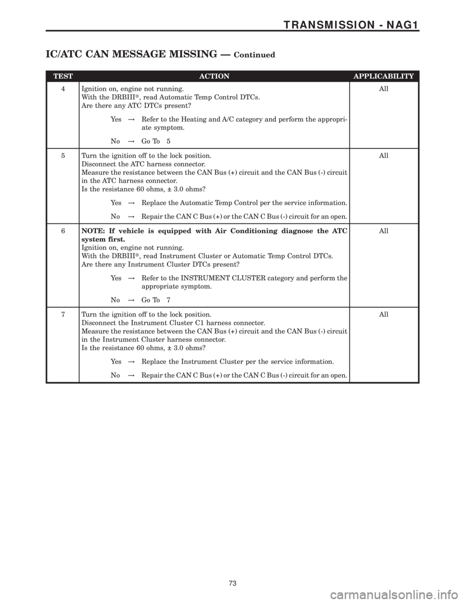
TEST ACTION APPLICABILITY
4 Ignition on, engine not running.
With the DRBIIIt, read Automatic Temp Control DTCs.
Are there any ATC DTCs present?All
Ye s!Refer to the Heating and A/C category and perform the appropri-
ate symptom.
No!Go To 5
5 Turn the ignition off to the lock position.
Disconnect the ATC harness connector.
Measure the resistance between the CAN Bus (+) circuit and the CAN Bus (-) circuit
in the ATC harness connector.
Is the resistance 60 ohms, 3.0 ohms?All
Ye s!Replace the Automatic Temp Control per the service information.
No!Repair the CAN C Bus (+) or the CAN C Bus (-) circuit for an open.
6NOTE: If vehicle is equipped with Air Conditioning diagnose the ATC
system first.
Ignition on, engine not running.
With the DRBIIIt, read Instrument Cluster or Automatic Temp Control DTCs.
Are there any Instrument Cluster DTCs present?All
Ye s!Refer to the INSTRUMENT CLUSTER category and perform the
appropriate symptom.
No!Go To 7
7 Turn the ignition off to the lock position.
Disconnect the Instrument Cluster C1 harness connector.
Measure the resistance between the CAN Bus (+) circuit and the CAN Bus (-) circuit
in the Instrument Cluster harness connector.
Is the resistance 60 ohms, 3.0 ohms?All
Ye s!Replace the Instrument Cluster per the service information.
No!Repair the CAN C Bus (+) or the CAN C Bus (-) circuit for an open.
73
TRANSMISSION - NAG1
IC/ATC CAN MESSAGE MISSING ÐContinued
Page 2239 of 2305
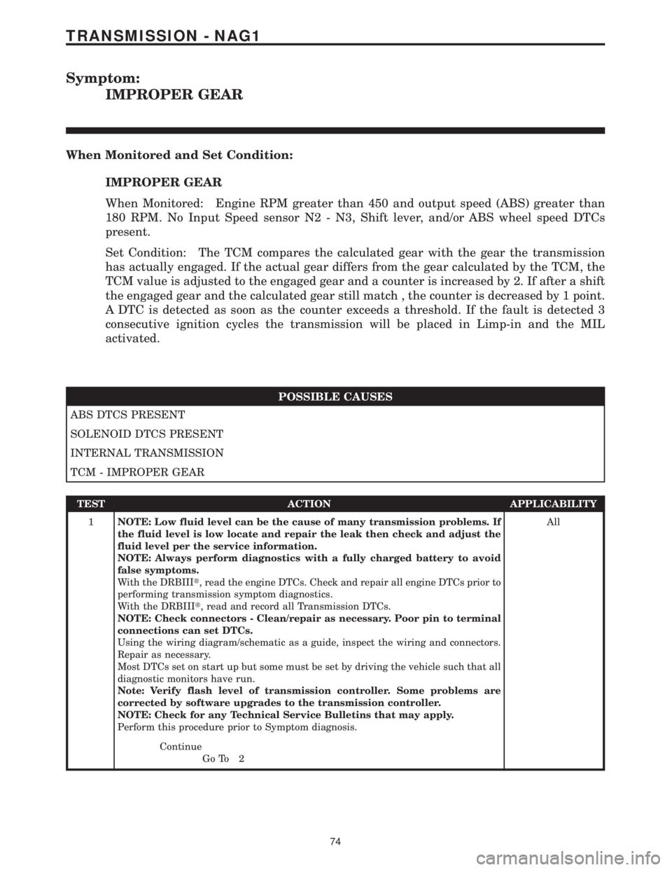
Symptom:
IMPROPER GEAR
When Monitored and Set Condition:
IMPROPER GEAR
When Monitored: Engine RPM greater than 450 and output speed (ABS) greater than
180 RPM. No Input Speed sensor N2 - N3, Shift lever, and/or ABS wheel speed DTCs
present.
Set Condition: The TCM compares the calculated gear with the gear the transmission
has actually engaged. If the actual gear differs from the gear calculated by the TCM, the
TCM value is adjusted to the engaged gear and a counter is increased by 2. If after a shift
the engaged gear and the calculated gear still match , the counter is decreased by 1 point.
A DTC is detected as soon as the counter exceeds a threshold. If the fault is detected 3
consecutive ignition cycles the transmission will be placed in Limp-in and the MIL
activated.
POSSIBLE CAUSES
ABS DTCS PRESENT
SOLENOID DTCS PRESENT
INTERNAL TRANSMISSION
TCM - IMPROPER GEAR
TEST ACTION APPLICABILITY
1NOTE: Low fluid level can be the cause of many transmission problems. If
the fluid level is low locate and repair the leak then check and adjust the
fluid level per the service information.
NOTE: Always perform diagnostics with a fully charged battery to avoid
false symptoms.
With the DRBIIIt, read the engine DTCs. Check and repair all engine DTCs prior to
performing transmission symptom diagnostics.
With the DRBIIIt, read and record all Transmission DTCs.
NOTE: Check connectors - Clean/repair as necessary. Poor pin to terminal
connections can set DTCs.
Using the wiring diagram/schematic as a guide, inspect the wiring and connectors.
Repair as necessary.
Most DTCs set on start up but some must be set by driving the vehicle such that all
diagnostic monitors have run.
Note: Verify flash level of transmission controller. Some problems are
corrected by software upgrades to the transmission controller.
NOTE: Check for any Technical Service Bulletins that may apply.
Perform this procedure prior to Symptom diagnosis.All
Continue
Go To 2
74
TRANSMISSION - NAG1
Page 2240 of 2305
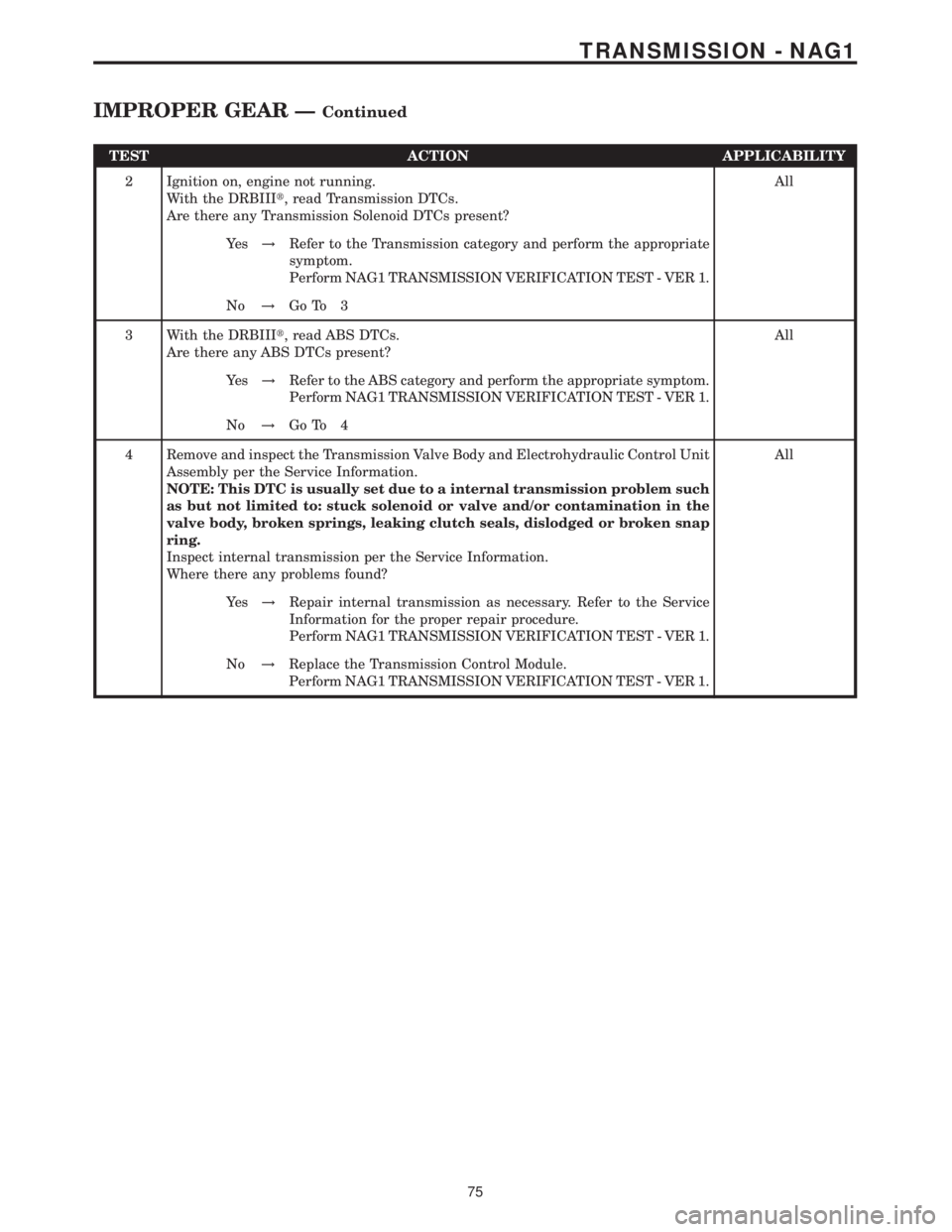
TEST ACTION APPLICABILITY
2 Ignition on, engine not running.
With the DRBIIIt, read Transmission DTCs.
Are there any Transmission Solenoid DTCs present?All
Ye s!Refer to the Transmission category and perform the appropriate
symptom.
Perform NAG1 TRANSMISSION VERIFICATION TEST - VER 1.
No!Go To 3
3 With the DRBIIIt, read ABS DTCs.
Are there any ABS DTCs present?All
Ye s!Refer to the ABS category and perform the appropriate symptom.
Perform NAG1 TRANSMISSION VERIFICATION TEST - VER 1.
No!Go To 4
4 Remove and inspect the Transmission Valve Body and Electrohydraulic Control Unit
Assembly per the Service Information.
NOTE: This DTC is usually set due to a internal transmission problem such
as but not limited to: stuck solenoid or valve and/or contamination in the
valve body, broken springs, leaking clutch seals, dislodged or broken snap
ring.
Inspect internal transmission per the Service Information.
Where there any problems found?All
Ye s!Repair internal transmission as necessary. Refer to the Service
Information for the proper repair procedure.
Perform NAG1 TRANSMISSION VERIFICATION TEST - VER 1.
No!Replace the Transmission Control Module.
Perform NAG1 TRANSMISSION VERIFICATION TEST - VER 1.
75
TRANSMISSION - NAG1
IMPROPER GEAR ÐContinued