MITSUBISHI 3000GT 1991 Service Manual
Manufacturer: MITSUBISHI, Model Year: 1991, Model line: 3000GT, Model: MITSUBISHI 3000GT 1991Pages: 1146, PDF Size: 76.68 MB
Page 1001 of 1146
INTERIOR - Front Seat52A-23
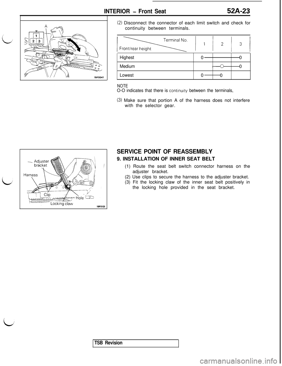
(2) Disconnect the connector of each limit switch and check for
continuity between terminals.
lFr= ) I / * / 3 j
Highest00
Medium0
Lowest0
0
NOTEO-O indicates that there is continurty between the terminals,
(3) Make sure that portion A of the harness does not interfere
with the selector gear.
SERVICE POINT OF REASSEMBLY9. INSTALLATION OF INNER SEAT BELT
(1) Route the seat belt switch connector harness on the
adjuster bracket.
(2) Use clips to secure the harness to the adjuster bracket.
(3) Fit the locking claw of the inner seat belt positively in
the locking hole provided in the seat bracket.
iJ
TSB Revision
Page 1002 of 1146
52A-24INTERIOR - Rear Seat
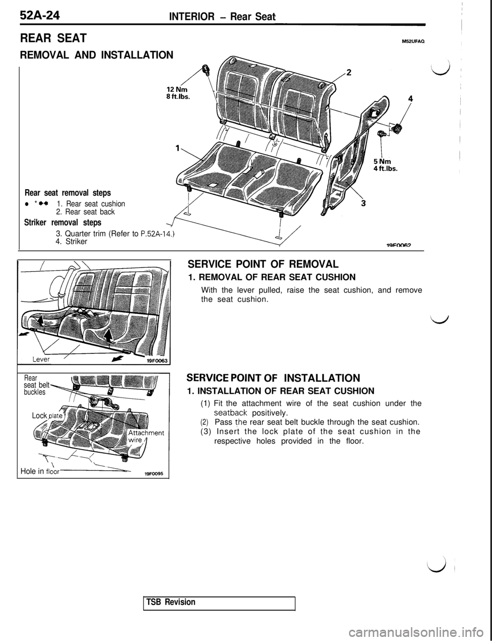
REAR SEAT
REMOVAL AND INSTALLATION
Rear seat removal steps
l * I)*1. Rear seat cushion
2. Rear seat back
Striker removal steps
3. Quarter trim (Refer to P.52A-14.)4. StrikerlQFtX-I67
Rearseat beltbuckles
Lock dat
Hole in flo\ori-19FOO95
SERVICE POINT OF REMOVAL1. REMOVAL OF REAR SEAT CUSHION
With the lever pulled, raise the seat cushion, and remove
the seat cushion.
SERVICE POINT OF INSTALLATION
1. INSTALLATION OF REAR SEAT CUSHION
(1) Fit the attachment wire of the seat cushion under theseatback positively.
(2)Pass the rear seat belt buckle through the seat cushion.
(3) Insert the lock plate of the seat cushion in the
respective holes provided in the floor.
TSB Revision
Page 1003 of 1146
INTERIOR - Seat Belt52A-25
Diagnosis connector”LJ’2OFOOl
GW161,338
With voltmeter___.-- -- ~~--~_. ___-- ..-.. .-.-
With multi-use tester
SEAT BELTM52UGEH
TROUBLESHOOTING GUIDE
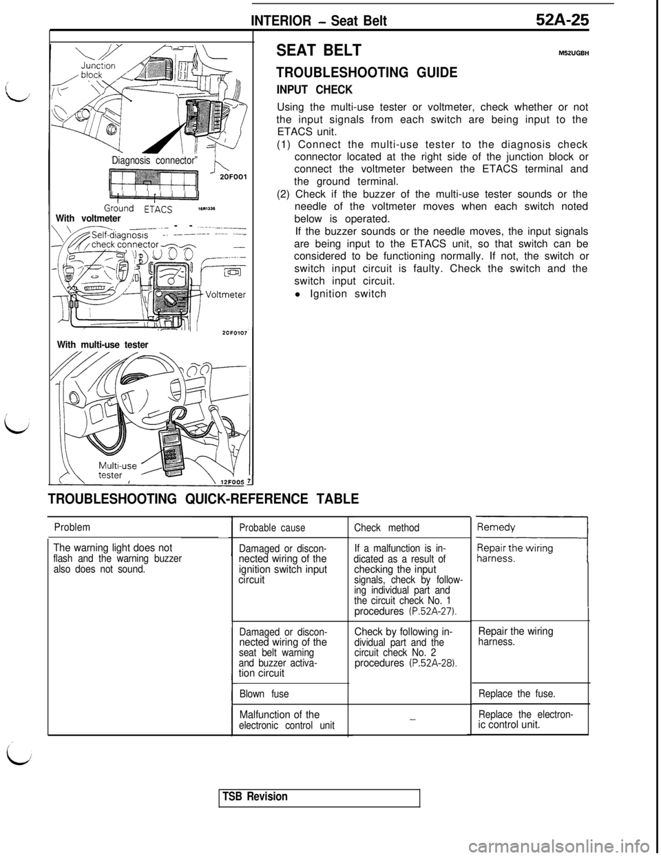
INPUT CHECKUsing the multi-use tester or voltmeter, check whether or not
the input signals from each switch are being input to the
ETACS unit.
(1) Connect the multi-use tester to the diagnosis check
connector located at the right side of the junction block or
connect the voltmeter between the ETACS terminal and
the ground terminal.
(2) Check if the buzzer of the multi-use tester sounds or the
needle of the voltmeter moves when each switch noted
below is operated.
If the buzzer sounds or the needle moves, the input signals
are being input to the ETACS unit, so that switch can be
considered to be functioning normally. If not, the switch or
switch input circuit is faulty. Check the switch and the
switch input circuit.
l Ignition switch
II
TROUBLESHOOTING QUICK-REFERENCE TABLE
Problem
The warning light does notflash and the warning buzzer
also does not sound.
Probable cause
Damaged or discon-nected wiring of the
ignition switch input
circuit
Damaged or discon-nected wiring of theseat belt warning
and buzzer activa-
tion circuit
Blown fuse
Malfunction of theelectronic control unitCheck method
If a malfunction is in-
dicated as a result of
checking the inputsignals, check by follow-
ing individual part and
the circuit check No. 1
procedures (P.52A-27).
Check by following in-dividual part and the
circuit check No. 2
procedures (P.52A-28).
-
Repair the wiringharness.
Replace the fuse.
Replace the electron-
ic control unit.
TSB Revision
Page 1004 of 1146
52A-26
INTERIOR - Seat Belt
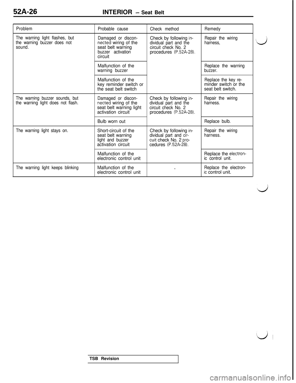
Problem
The warning light flashes, but
the warning buzzer does not
sound.Probable cause
Damaged or discon-netted
wiring of the
seat belt warning
buzzer activationcircuit
Check method
Check by following in-dividual part and the
circuit check No. 2
procedures (P.52A-28).
Remedy
Repair the wiring
harness,
The warning buzzer sounds, but
the warning light does not flash.
The warning light stays on.
The warning light keeps blinking
Malfunction of theReplace the warning
warning buzzerbuzzer.
Malfunction of theReplace the key re-key reminder switch orminder switch or the
the seat belt switchseat belt switch.
Damaged or discon-Check by following in-Repair the wiringnetted wiring of thedividual part and theharness.seat belt warning lightcircuit check No. 2activation circuitprocedures (P.52A-28).
Bulb worn outReplace bulb.
Short-circuit of theCheck by following in-Repair the wiringseat belt warningdividual part and cir-harness.
light and buzzer
cuit check No. 2 pro-activation circuit
cedures (P.52A-28).
Malfunction of theReplace the electron-electronic control unitic control unit.
Malfunction of the-Replace the electron-electronic control unitic control unit.
‘dTSB Revision
Page 1005 of 1146
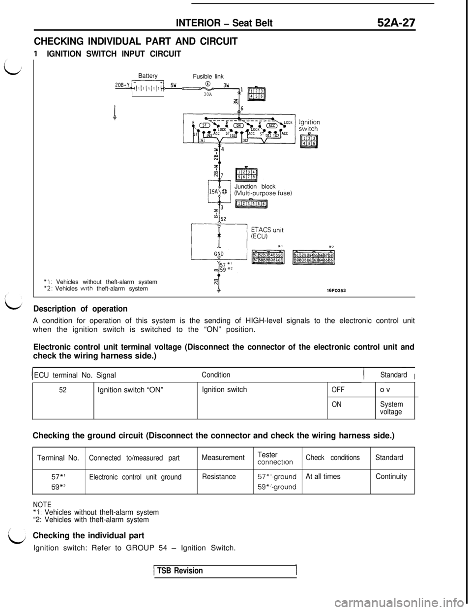
INTERIOR - Seat Belt52A-27
CHECKING INDIVIDUAL PART AND CIRCUIT
IGNITION SWITCH INPUT CIRCUITBattery
Fusible link
2oB-y~~/l,l(l,l,,~~ !jw u03w
30AJunction block
*I : Vehicles without theft-alarm system“2: Vehicles wtth theft-alarm system16FO35.3
It/Description of operationA condition for operation of this system is the sending of HIGH-level signals to the electronic control unit
when the ignition switch is switched to the “ON” position.
Electronic control unit terminal voltage (Disconnect the connector of the electronic control unit andcheck the wiring harness side.)
IECU terminal No. SignalCondition-1 ~StandardI
52Ignition switch “ON”Ignition switchOFF
ONov
System
voltageChecking the ground circuit (Disconnect the connector and check the wiring harness side.)
Terminal No.Connected to/measured part
57,’Electronic control unit ground
59*2
NOTE
*I : Vehicles without theft-alarm system
“2: Vehicles with theft-alarm systemMeasurementTester
connectronCheck conditionsStandard
Resistance
57*‘-groundAt all timesContinuity
59*.‘-groundChecking the individual part
Ignition switch: Refer to GROUP 54
- Ignition Switch.
1 TSB Revision
Page 1006 of 1146
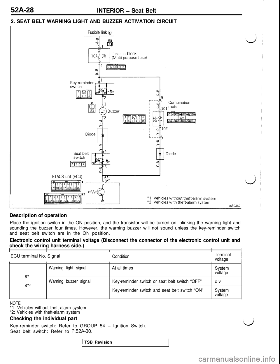
52A-28INTERIOR - Seat Belt2. SEAT BELT WARNING LIGHT AND BUZZER ACTIVATION CIRCUIT
Fusible link @
Junctron block(Multr-purpose fuse)
ETACS unit (ECU)Description of operation
Place the ignition switch in the ON position, and the transistor will be turned on, blinking the warning light and
sounding the buzzer four times. However, the warning buzzer will not sound unless the key-reminder switch
and seat belt switch are in the ON position.
Electronic control unit terminal voltage (Disconnect the connector of the electronic control unit andcheck the wiring harness side.)
IIIIIECU terminal No. Signal
ConditionTerminal
voltageI\!
Warning light signalAt all timesSystem
6*1voltage
Warning buzzer signal
Key-reminder switch or seat belt switch “OFF”ov8*2
Key-reminder switch and seat belt switch “ON”System
voltage
NOTE“1. Vehicles without theft-alarm system
“2: Vehicles with theft-alarm systemChecking the individual part
Key-reminder switch: Refer to GROUP 54
- Ignition Switch.dSeat belt switch: Refer to
P.5?A-30.
1 TSB Revision
Page 1007 of 1146
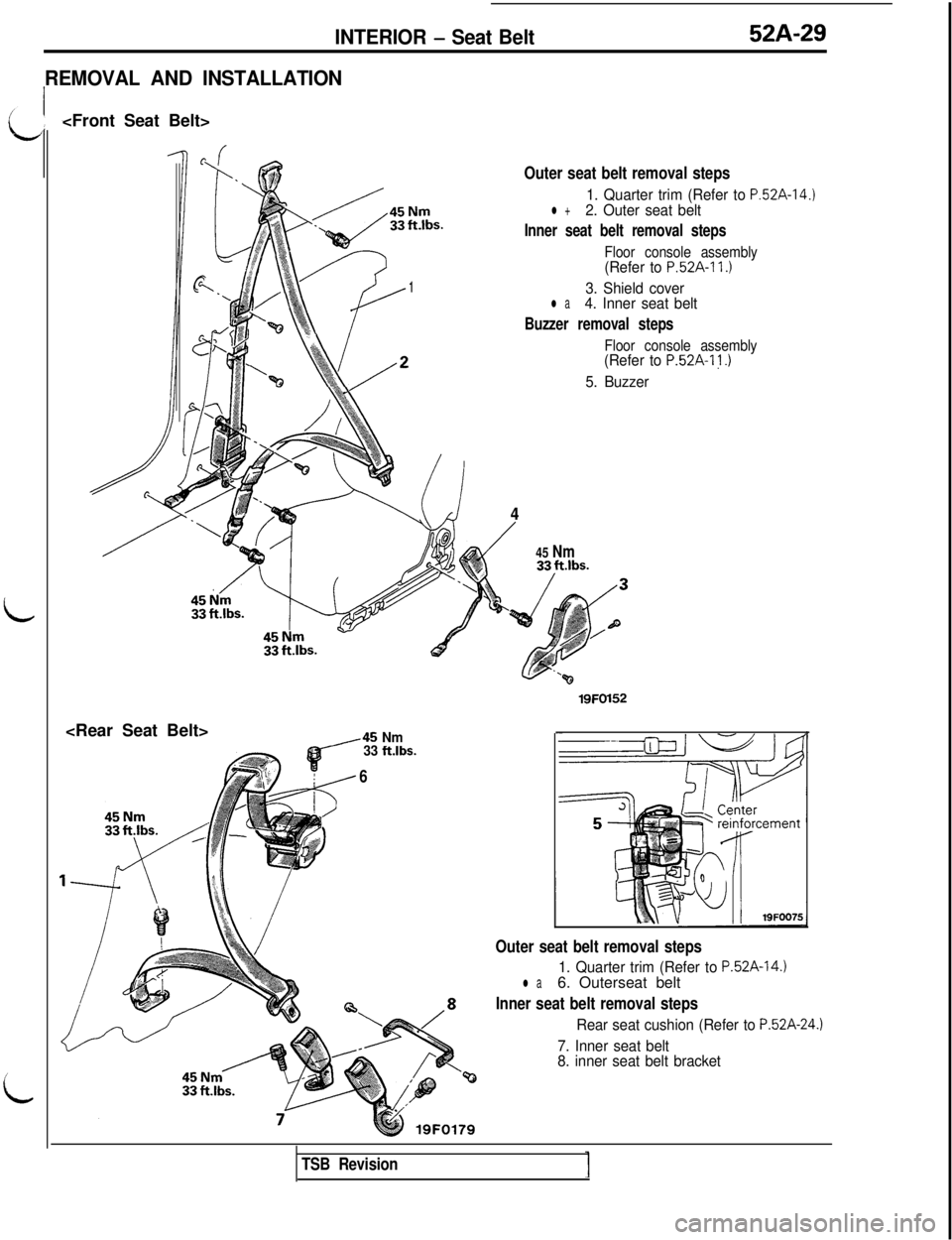
INTERIOR - Seat Belt52A-29
REMOVAL AND INSTALLATION
---nOuter seat belt removal steps
7 -$g%,* ‘9‘A. .‘j,,,
,y4
PII \,:0,+i.1$_ a1
y’
r‘J w
\7
\,%/
%
D
$!& ,2
4,.$#.,
,45 Nm
33 ftlbs.
6
1. Quarter trim (Refer to P.52A-14l +2. Outer seat belt
Inner seat belt removal steps
Floor console assembly(Refer to P.52A-11 .I
3. Shield coverl a4. Inner seat belt
Buzzer removal steps
Floor console assembly(Refer to P.52A-1 j .)
5. Buzzer
4
/45 Nm
.)
19FOl52
Outer seat belt removal steps
1. Quarter trim (Refer to P.52A-14.)l a6. Outerseat belt
Inner seat belt removal steps
Rear seat cushion (Refer to P.52A-24.)
7. Inner seat belt
8. inner seat belt bracket
TSB Revision
Page 1008 of 1146
52A-30
INTERIOR - Seat Belt
16M456
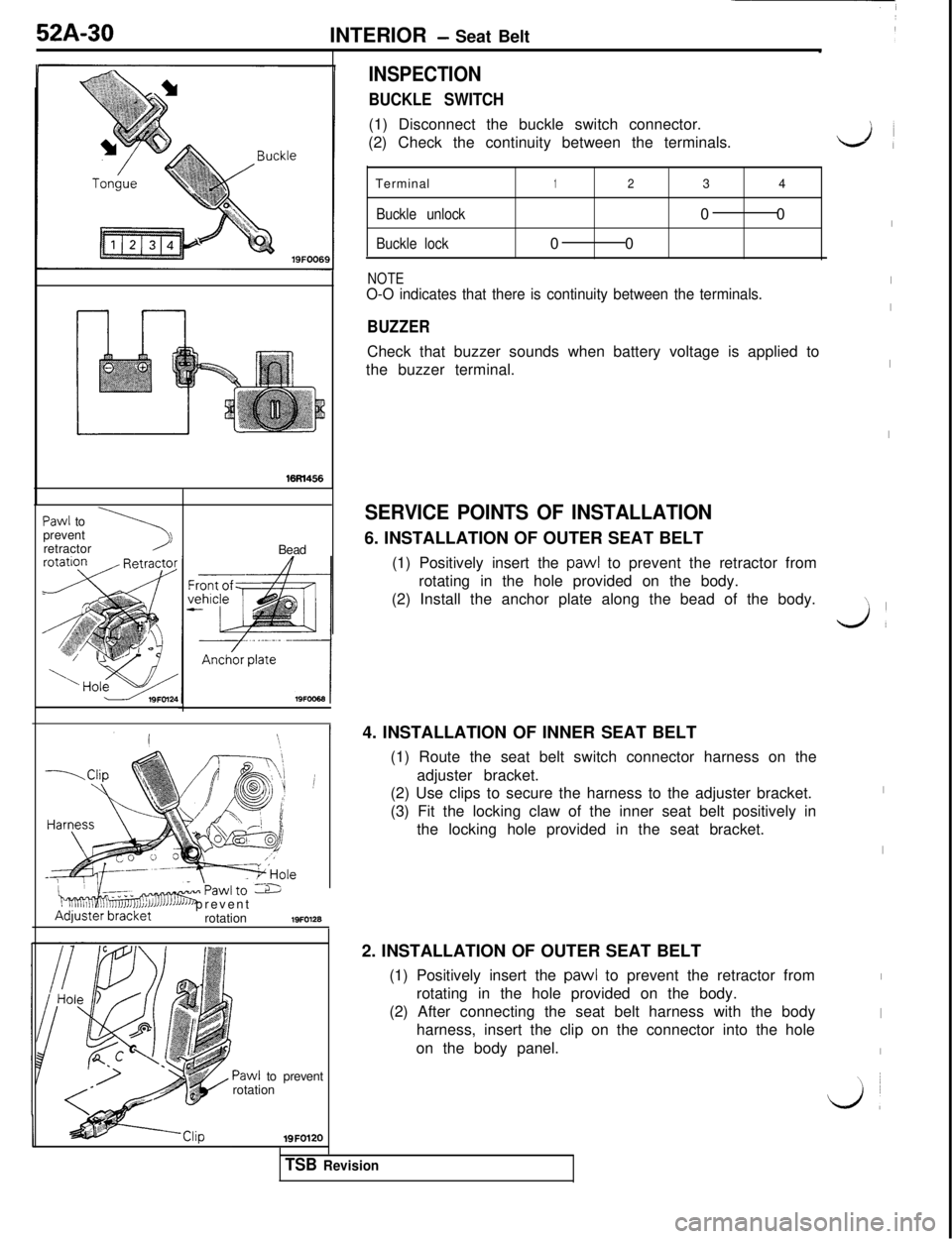
NOTEO-O indicates that there is continuity between the terminals.
BUZZERCheck that buzzer sounds when battery voltage is applied to
the buzzer terminal.
Paw1 to
prevent
\1retractor
Bead
INSPECTION
BUCKLE SWITCH(1) Disconnect the buckle switch connector.
(2) Check the continuity between the terminals.
Terminal
1234
Buckle unlock00
Buckle lock00
i
“..i,Tlmdsmrawlro -6I J3JJAdjuster’bracketJ’JJ’ prevent
rotation19FO128
Paw1 to prevent
rotation19FO120
SERVICE POINTS OF INSTALLATION6. INSTALLATION OF OUTER SEAT BELT
(1) Positively insert the
paw1 to prevent the retractor from
rotating in the hole provided on the body.
(2) Install the anchor plate along the bead of the body.
4. INSTALLATION OF INNER SEAT BELT
(1) Route the seat belt switch connector harness on the
adjuster bracket.
(2) Use clips to secure the harness to the adjuster bracket.
(3) Fit the locking claw of the inner seat belt positively in
the locking hole provided in the seat bracket.
2. INSTALLATION OF OUTER SEAT BELT
(1) Positively insert the
paw1 to prevent the retractor from
rotating in the hole provided on the body.
(2) After connecting the seat belt harness with the body
harness, insert the clip on the connector into the hole
on the body panel.
LA
I
I
I
I
I\
Jl
I
I
I
I
I
\ ~
L&l
TSB Revision
Page 1009 of 1146
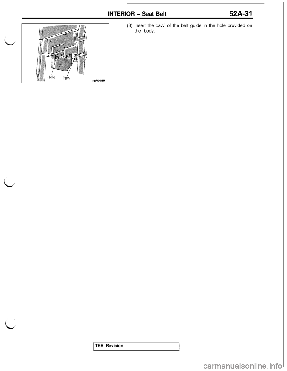
INTERIOR - Seat Belt52A-31(3) Insert the pawl of the belt guide in the hole provided on
the body.
TSB Revision
Page 1010 of 1146
