MITSUBISHI 3000GT 1991 Service Manual
Manufacturer: MITSUBISHI, Model Year: 1991, Model line: 3000GT, Model: MITSUBISHI 3000GT 1991Pages: 1146, PDF Size: 76.68 MB
Page 1041 of 1146
:
id
cSUPPLEMENTAL RESTRAINT SYSTEM (SRS)
- Troubleshooting 52B-31
1 CONTINUED FROM PREVIOUS PAGE(
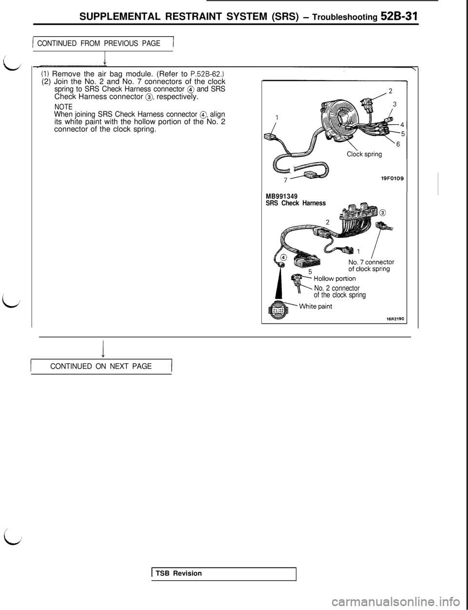
(1) Remove the air bag module. (Refer to P.52B-62.)(2) Join the No. 2 and No. 7 connectors of the clock
spring to SRS Check Harness connector @ and SRSCheck Harness connector 0, respectively.
NOTEWhen joining SRS Check Harness connector 0, alignits white paint with the hollow portion of the No. 2
connector of the clock spring.
19FO109
MB991349
SRS Check Harness
No. 2 connector
of the clock spring
16R2190
I
ICONTINUED ON NEXT PAGEI
i
1 TSB Revision
Page 1042 of 1146
52B-32 SUPPLEMENTAL RESTRAINT SYSTEM (SRS) - Troubleshooting
CONTINUED FROM PREVIOUS PAGE
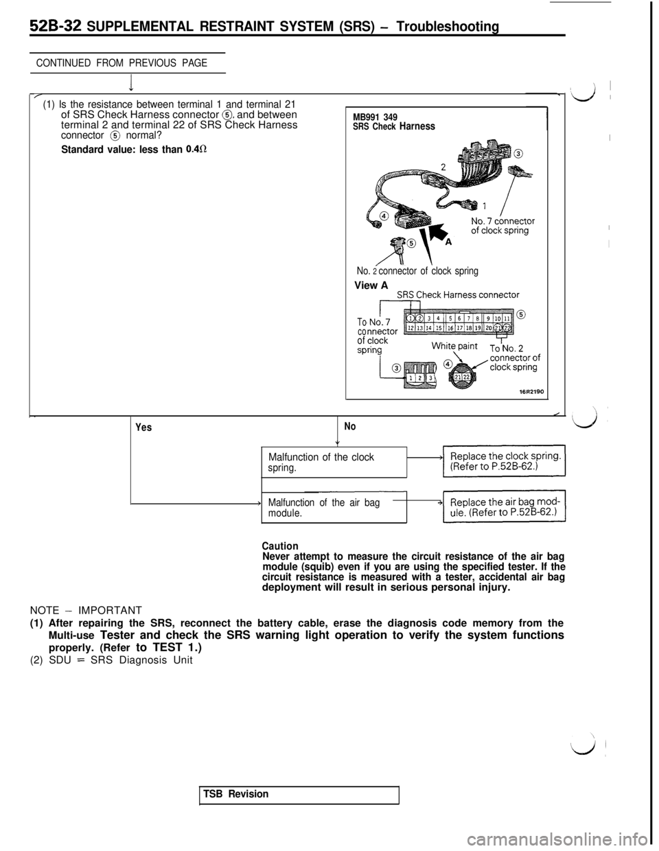
I/(1) Is the resistance between terminal 1 and terminal 21of SRS Check Harness connector @ and between
terminal 2 and terminal 22 of SRS Check HarnessMB991 349SRS Check Harnessconnector @ normal?
Standard value: less than 0.4R
No. 2 connector of clock springView A
To
co
of
SP
16R2190.
Yes
/
No
*
Malfunction of the clockspring.>V/
>Malfunction of the air bag
module.
CautionNever attempt to measure the circuit resistance of the air bag
module (squib) even if you are using the specified tester. If the
circuit resistance is measured with a tester, accidental air bagdeployment will result in serious personal injury.
NOTE
- IMPORTANT
(1) After repairing the SRS, reconnect the battery cable, erase the diagnosis code memory from the
Multi-use Tester and check the SRS warning light operation to verify the system functions
properly. (Refer to TEST 1.)
(2) SDU
= SRS Diagnosis Unit
TSB Revision
’ I
‘d ’
I
I
I
Page 1043 of 1146
SUPPLEMENTAL RESTRAINT SYSTEM (SRS) - Troubleshooting 52B-33
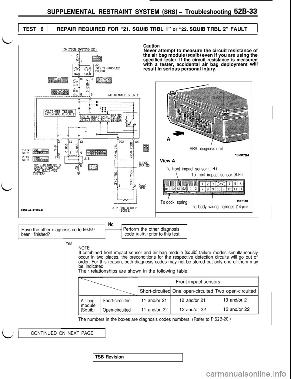
1 TEST 6 )REPAIR REQUIRED FOR “21. SQUIB TRBL 1” or “22. SQUIB TRBL 2” FAULT1
i
FRONTSIDE
Ez
IGNITION SWITCH(IG1)CautionNever attempt to measure the circuit resistance of
the air bag module
(squib) even if you are using thespecified tester. If the circuit resistance is measuredwith a tester, accidental air bag deployment will
result in serious personal injury.
SRS DIAGNOSIS UNIT
------I
SELF-DIAGNOISISCHECK CONNECTOR(FOR MULTI-USETESTER)ms!+Ax-Pls95-Y
J/B
AIR (BSAgGU#DULEView A
SRS diagnosisunit
13uo704
To front impact sensor (L.H.1
\To front impact sensor (R.H.)
Todock springI19FOllOTo body wiring harness (IQpin)
No
Have the other diagnosis code test(s)/> Perform the other diagnosis
been finished?code test(s) prior to this test.
/I
Yes
NOTE
If combined front impact sensor and air bag module (squib) failure modes simultaneously
occur in two places, the preconditions for the respective detection circuits will go out of
order. For this reason, both diagnosis codes may not be stored but only one of them may
be indicated.Their relationships are shown in the following table.
Front impact sensors
Short-circuited One open-circuited Two open-circuited
Air bagShort-circuited11 and/or 2112 and/or 2113 and/or 21
module(Squib)Open-circuited11 and/or .2212 and/or 2213 and/or 22
The numbers in the boxes are diagnosis codes numbers. (Refer to P.52B-20.)
LICONTINUED ON NEXT PAGE
1 TSB Revision
Page 1044 of 1146
526-34 SUPPLEMENTAL RESTRAINT SYSTEM (SRS) - Troubleshooting
CONTINUED FROM PREVIOUS PAGE
c
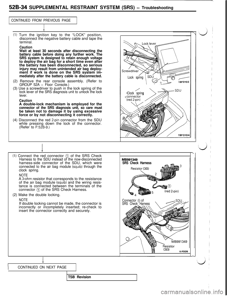
(1) Turn the ignition key to the “LOCK” position,
disconnect the negative battery cable and tape the
terminal.
CautionWait at least 30 seconds after disconnecting the
battery cable before doing any further work. The
SRS system is designed to retain enough voltageto deploy the air bag for a short time even after
the battery has been disconnected, so serious
injury may result from unintended air bag deploy-ment if work is done on the SRS system im-
mediately after the battery cable is disconnected.(2) Remove the rear console assembly. (Refer to
GROUP 52A - Floor Console.)(3) Use a screwdriver to push in the lock spring of the
lock lever of the SRS diagnosis unit to unlock the locklever.
CautionA double-lock mechanism is employed for the
connector of the SRS diagnosis unit, so care mustbe taken not to damage it by using excessive
force or by not disconnecting it correctly.
(4) Disconnect the red
2-pin connector from the SDU
while pressing down the lock of the connector.
(Refer to
P.52B-9.)
/Lock spring
/Clock spring
I\(I) Connect the red connector @ of the SRS CheckHarness to the SDU instead of the now-disconnectedharness-side connector of the SDU, which were
connected to the air bag module (squib) through the
clock spring.
NOTE
SRS Check HarnessA
3-ohm resistor that corresponds to the resistance
of the air bag module (squib) and the wiring resis-
tance is connected between the terminals of the
connector
@ of the SRS Check Harness.
(2) Make the double locking.
NOTEIf double locking cannot be made, the connector is
incorrectly or incompletely inserted; re-check to
insert the connector correctly and securely.Connector @ ofSRS Check Harness
(3R)19 FOO9:
1
/
ICONTINUED ON NEXT PAGE
TSB Revision
Page 1045 of 1146
I
L
:
L;
1’SUPPLEMENTAL RESTRAINT SYSTEM (SRS)
- Troubleshooting 526-35
1 CONTINUED FROM PREVIOUS PAr/
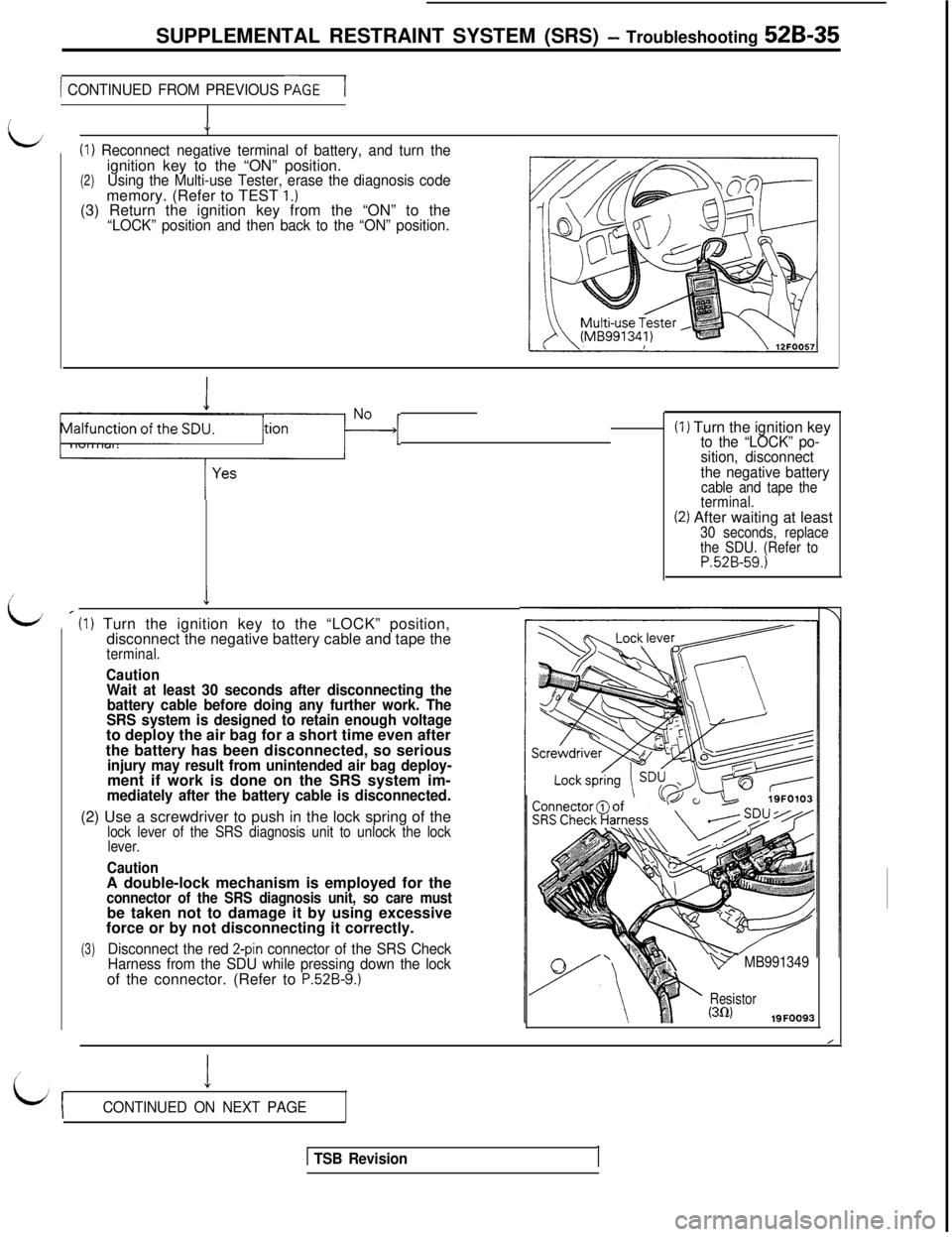
J(I)
Reconnect negative terminal of battery, and turn the
(2)ignition key to the “ON” position.Using the Multi-use Tester, erase the diagnosis codememory. (Refer to TEST 1.)(3) Return the ignition key from the “ON” to the
“LOCK” position and then back to the “ON” position.
Is the SRS warning light operation)?IMalfunction-[
_Iv
’ (I) Turn the ignition key to the “LOCK” position,
disconnect the negative battery cable and tape the
terminal.
CautionWait at least 30 seconds after disconnecting the
battery cable before doing any further work. The
SRS system is designed to retain enough voltageto deploy the air bag for a short time even after
the battery has been disconnected, so serious
injury may result from unintended air bag deploy-ment if work is done on the SRS system im-
mediately after the battery cable is disconnected.(2) Use a screwdriver to push in the lock spring of the
lock lever of the SRS diagnosis unit to unlock the lock
lever.
CautionA double-lock mechanism is employed for the
connector of the SRS diagnosis unit, so care mustbe taken not to damage it by using excessive
force or by not disconnecting it correctly.
(3)Disconnect the red 2-pin connector of the SRS Check
Harness from the SDU while pressing down the lockof the connector. (Refer to
P.52B-9.)(I) Turn the ignition key
to the “LOCK” po-
sition, disconnect
the negative battery
cable and tape the
terminal.
(2) After waiting at least30 seconds, replace
the SDU. (Refer to
P.52B-59.)4
v MB991349
Resistor(302)19FOO93
I
LijCONTINUED ON NEXT PAGE
1 TSB RevisionI
Page 1046 of 1146
52B-36 SUPPLEMENTAL RESTRAINT SYSTEM (SRS) - Troubleshooting
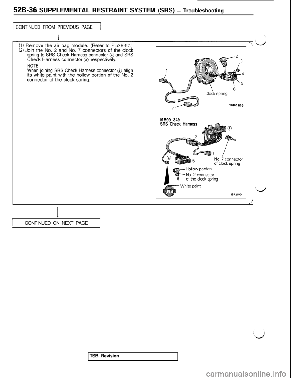
1 CONTINUED FROM PREVIOUS PAGE1(I) Remove the air bag module. (Refer to
P.52B-62.)(2) Join the No. 2 and No. 7 connectors of the clockspring to SRS Check Harness connector @ and SRSCheck Harness connector 0, respectively.
NOTEWhen joining SRS Check Harness connector 0, alignits white paint with the hollow portion of the No. 2
connector of the clock spring.
19FO109
MB991349
SRS Check Harness
No.2 connector
of the clock spring
I
ICONTINUED ON NEXT PAGEI
\
/
TSB Revision
Page 1047 of 1146
LSUPPLEMENTAL RESTRAINT SYSTEM (SRS)
- Troubleshooting 52B-37
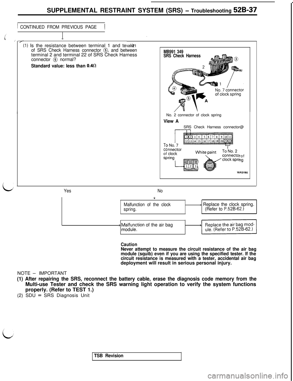
1 CONTINUED FROM PREVIOUS PAGE1(I) Is the resistance between terminal 1 and termir
ial 21of SRS Check Harness connector 0, and betweenterminal 2 and terminal 22 of SRS Check Harness
connector @ normal?
Standard value: less than 0.4fl
MB991 349
SRS Check HarnessNo. 2 connector of clock spring
View ASRS Check Harness connector@
Tocoof
sProfng
YesNo
Malfunction of the clock
spring.
+ ;z;;;tion of the air bag
> Replace the clock spring.
(Refer to P.52B-62.)
CautionNever attempt to measure the circuit resistance of the air bag
module (squib) even if you are using the specified tester. If the
circuit resistance is measured with a tester, accidental air bagdeployment will result in serious personal injury.
NOTE
- IMPORTANT
(1) After repairing the SRS, reconnect the battery cable, erase the diagnosis code memory from theMulti-use Tester and check the SRS warning light operation to verify the system functions
properly. (Refer to TEST 1.)
(2) SDU
= SRS Diagnosis Unit
i
TSB Revision
Page 1048 of 1146
52B-38 SUPPLEMENTAL RESTRAINT SYSTEM (SRS) - Troubleshooting
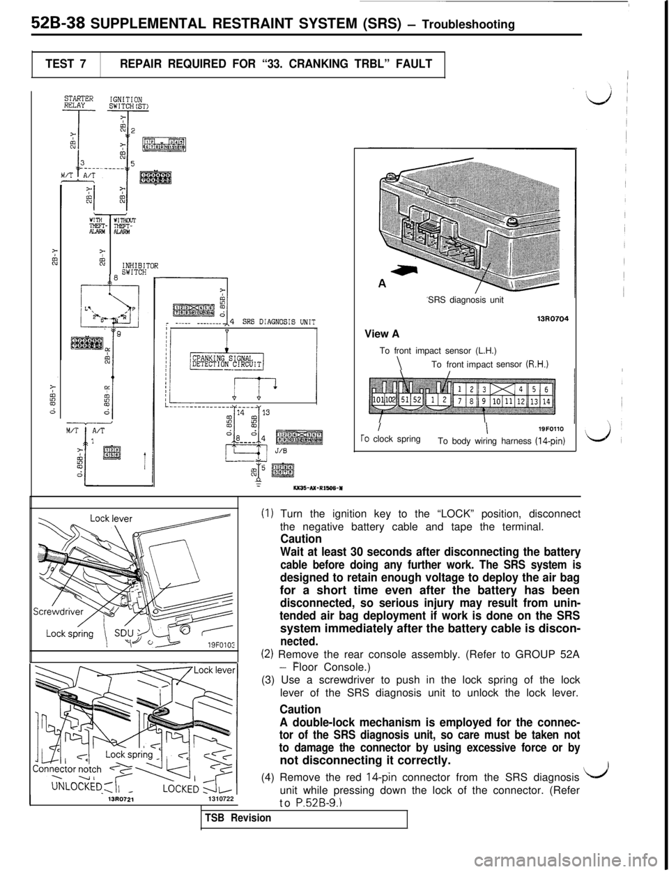
TEST 7REPAIR REQUIRED FOR “33. CRANKING TRBL” FAULT1
STARTERHULAYIGNITIONSWITCH(ST>
7%INHIBITOR
10SWITCH
FI
pkEE&r -...__ -_-_-___I4SRS DIAGNOSIS UNITI
I---..-___________ - ____
2
14 13
!z
CLYL
da d4--__J/S
-A) @g
:6x36-NC-R1606-USRS diagnosis unit
13R0704View A
To front impact sensor (L.H.)
\To frontimpactsensor (R.H.)
II19FOllOTo clock spring
To body wiring harness (14-pin)
(I) Turn the ignition key to the “LOCK” position, disconnect
the negative battery cable and tape the terminal.
Caution
Wait at least 30 seconds after disconnecting the battery
cable before doing any further work. The SRS system is
designed to retain enough voltage to deploy the air bagfor a short time even after the battery has been
disconnected, so serious injury may result from unin-
tended air bag deployment if work is done on the SRSsystem immediately after the battery cable is discon-
nected.
(2) Remove the rear console assembly. (Refer to GROUP 52A-.
13R07211310722
- Floor Console.)
(3) Use a screwdriver to push in the lock spring of the lock
lever of the SRS diagnosis unit to unlock the lock lever.
Caution
A double-lock mechanism is employed for the connec-
tor of the SRS diagnosis unit, so care must be taken not
to damage the connector by using excessive force or bynot disconnecting it correctly.
(4) Remove the red
14-pin connector from the SRS diagnosis
unit while pressing down the lock of the connector. (Refer
to
P52B-9.1
I/’
TSB Revision
Page 1049 of 1146
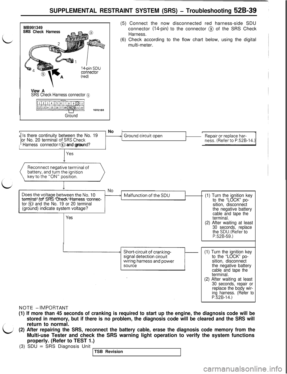
SUPPLEMENTAL RESTRAINT SYSTEM (SRS) - Troubleshooting 52B-39
MB991349SRS Check Harness
connector
View ASRS Check Harness connector @
Ground
II No(5) Connect the now disconnected red harness-side SDU
connector
(14-pin) to the connector @ of the SRS Check
Harness.(6) Check according to the flow chart below, using the digital
multi-meter.
IIIIs there continuity between the No. 191 or No. 20 terminal ofi;RSCheck‘1 ~~~~~;,0~~~~~~.~~~-14.~r1 Ground ‘jrcuit Open1Harness connector @ and ground?
Reconnect negative terminal of
(()
terminal (of SRS Check Harness connec-
tor 0) and the No. 19 or 20 terminal(ground) indicate system voltage?NOTE
- IMPOR
TANT
Yes
(1) Turn the ignition key
to the “LOCK” po-
sition, disconnect
the negative battery
cable and tape the
terminal.
(2) After waiting at least30 seconds, replacethe SDU.(Refer toP.52B-59.)
(1) Turn the ignition key
to the “LOCK” po-
sition, disconnect
the negative battery
cable and tape theterminal.
(2) After waiting at least
30 seconds, repair orreplace the body wir-ing harness. (Refer toP.52B-14.)
(1) If more than 45 seconds of cranking is required to start up the engine, the diagnosis code will be
stored in memory, but if there is no problem, the diagnosis code will be cleared and the SRS willreturn to normal.
(2) After repairing the SRS, reconnect the battery cable, erase the diagnosis code memory from theMulti-use Tester and check the SRS warning light operation to verify the system functions
properly. (Refer to TEST 1.)
(3) SDU
= SRS Diagnosis Unit
TSB Revision
Page 1050 of 1146
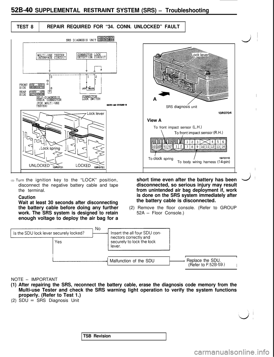
52B-40 SUPPLEMENTAL ,RESTRAINT SYSTEM (SRS) - Troubleshooting
TEST 8REPAIR REQUIRED FOR “34. CONN. UNLOCKED” FAULT
SRS DIAGNOSIS UNIT-
r
--
L
FRONTSIDE
EESELF-DIAGNOSISCHECK CONNECTORLOCK SWITCH(FOR MULTI-USETESTER)KXB-AX-RIRW-YSRS diagnoskunit
13RQ7Q4View A
To front impact sensor
(L.H.)Todlock spring
I19F0110
To body wiring harness (14-pin)
(1) Turn the ignition key to the “LOCK” position,
disconnect the negative battery cable and tape
the terminal.
Caution
Wait at least 30 seconds after disconnectingthe battery cable before doing any further
work. The SRS system is designed to retainenough voltage to deploy the air bag for ashort time even after the battery has been
disconnected, so serious injury may result
from unintended air bag deployment if, work
is done on the SRS system immediately afterthe battery cable is disconnected.
(2) Remove the floor console. (Refer to GROUP
52A
- Floor Console.)
Is the SDU lock lever securely locked?~JII’~~
I11I
-1 Malfunction of the SDU> Replace the SDU.
(Refer to P.52B-59.1INOTE
- IMPORTANT
(1) After repairing the SRS, reconnect the battery cable, erase the diagnosis code memory from theMulti-use Tester and check the SRS warning light operation to verify the system functions
properly. (Refer to Test 1.)
(2) SDU
= SRS Diagnosis Unit
I
LA
I
I
I
J
TSB Revision