MITSUBISHI 3000GT 1991 Service Manual
Manufacturer: MITSUBISHI, Model Year: 1991, Model line: 3000GT, Model: MITSUBISHI 3000GT 1991Pages: 1146, PDF Size: 76.68 MB
Page 961 of 1146
EXTERIOR - Aero Parts
18FO257
RearFrontView
A_ View B
Adhesive
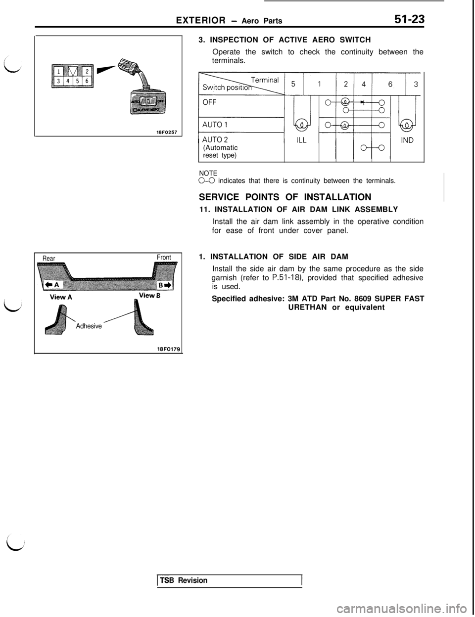
18FO17533. INSPECTION OF ACTIVE AERO SWITCH
Operate the switch to check the continuity between the
terminals.
(Automatic
reset type)
NOTEO-0 indicates that there is continuity between the terminals.
SERVICE POINTS OF INSTALLATION
11. INSTALLATION OF AIR DAM LINK ASSEMBLY
Install the air dam link assembly in the operative condition
for ease of front under cover panel.
1. INSTALLATION OF SIDE AIR DAM
Install the side air dam by the same procedure as the side
garnish (refer to
P.51-181, provided that specified adhesive
is used.
Specified adhesive: 3M ATD Part No. 8609 SUPER FAST
URETHAN or equivalent
I---TSB Revision
Page 962 of 1146
51-24EXTERIOR - Windshield Wiper and Washer
WINDSHIELD WIPER AND WASHER
Junctionblock
DiagnosisconnectorA/;
\\ZOFOOl?
GroundETACSWith voltmeter
Diagnosis checkconnectorWith multi-use tester
TROUBLESHOOTING GUIDEINPUT CHECK
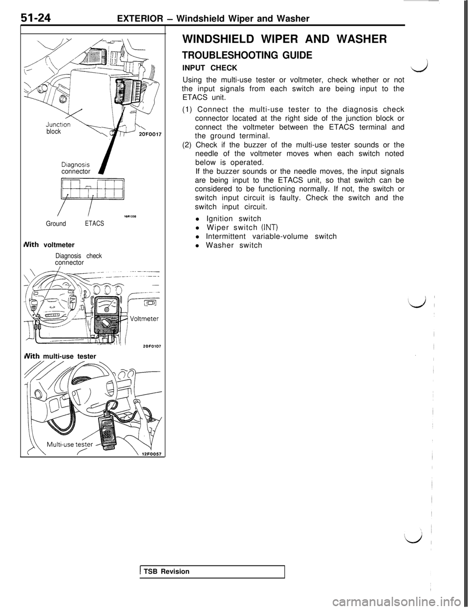
\JUsing the multi-use tester or voltmeter, check whether or not
the input signals from each switch are being input to the
ETACS unit.
(1) Connect the multi-use tester to the diagnosis check
connector located at the right side of the junction block or
connect the voltmeter between the ETACS terminal and
the ground terminal.
(2) Check if the buzzer of the multi-use tester sounds or the
needle of the voltmeter moves when each switch noted
below is operated.
If the buzzer sounds or the needle moves, the input signals
are being input to the ETACS unit, so that switch can be
considered to be functioning normally. If not, the switch or
switch input circuit is faulty. Check the switch and the
switch input circuit.
l Ignition switch
l Wiper switch
(INT)l Intermittent variable-volume switch
l Washer switch
1 TSB Revision
Page 963 of 1146
EXTERIOR - Windshield Wiper and Washer51-25
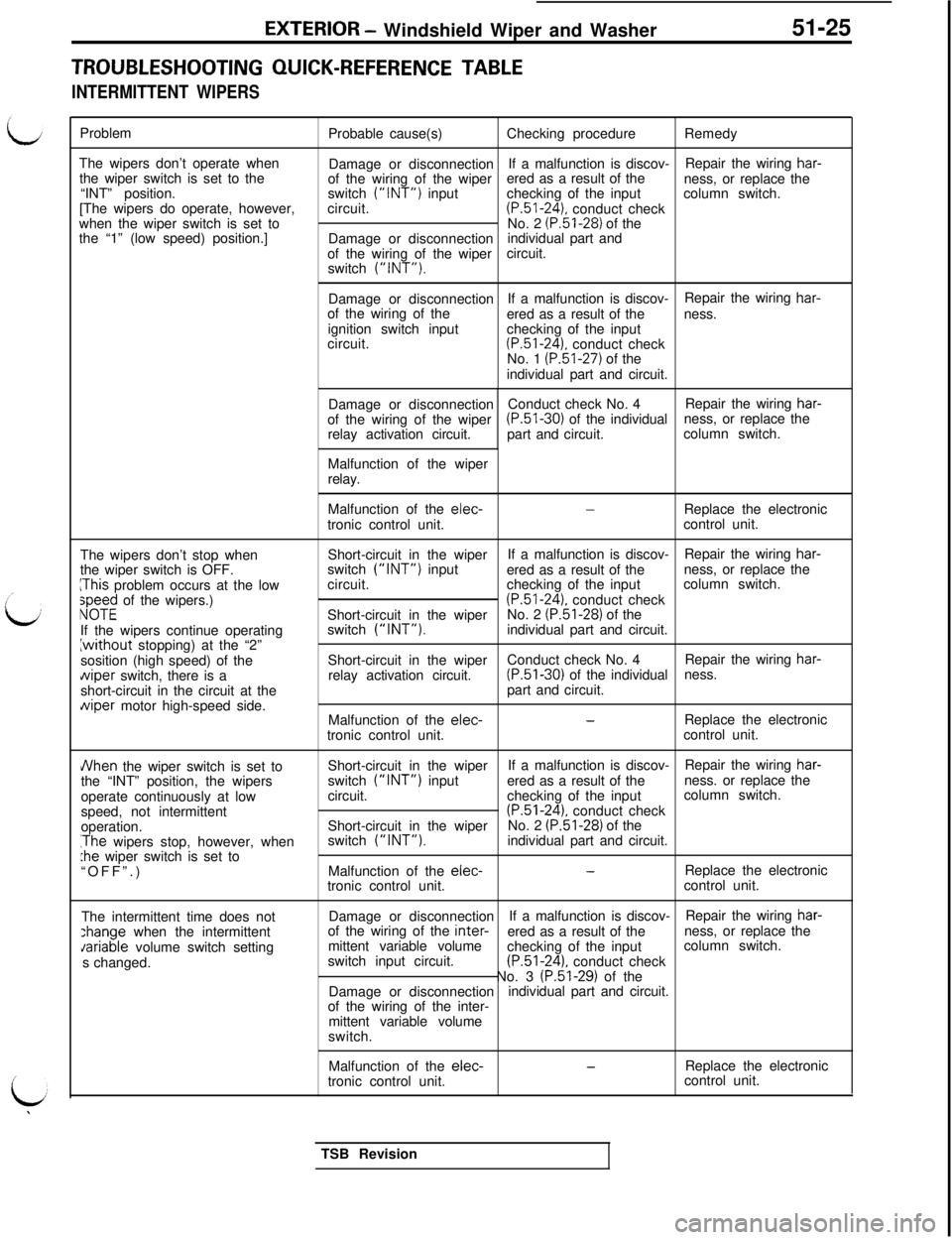
TROUBLESHOOTING QUICK-REFERENCE TABLE
INTERMITTENT WIPERSProblem
The wipers don’t operate when
the wiper switch is set to the
“INT” position.
[The wipers do operate, however,
when the wiper switch is set to
the “1” (low speed) position.]Probable cause(s)Checking procedureRemedy
Damage or disconnectionIf a malfunction is discov-
of the wiring of the wiperRepair the wiring
har-ered as a result of the
switch
(“INT”) inputness, or replace the
checking of the inputcolumn switch.
circuit.(P.51-24). conduct check
No. 2 (P.51-28) of the
Damage or disconnectionindividual part and
of the wiring of the wipercircuit.
switch
(“INT”).Damage or disconnectionIf a malfunction is discov-
of the wiring of theRepair the wiring
har-ered as a result of theness.
ignition switch input
circuit.checking of the input
(P.51-24). conduct check
No. 1 (P.51-27) of the
individual part and circuit.
Damage or disconnectionConduct check No. 4Repair the wiring
har-of the wiring of the wiper(P.51-30) of the individualness, or replace the
relay activation circuit.part and circuit.column switch.
Malfunction of the wiper
relay.
The wipers don’t stop when
the wiper switch is OFF.
IThis problem occurs at the low;p;$ of the wipers.)
If the wipers continue operating{without stopping) at the “2”
sosition (high speed) of the
uiper switch, there is a
short-circuit in the circuit at the
Ylviper motor high-speed side.
JVhen the wiper switch is set to
the “INT” position, the wipers
operate continuously at low
speed, not intermittent
operation.
IThe wipers stop, however, when:he wiper switch is set to
“OFF”.)
The intermittent time does not:hange when the intermittent
Jariable volume switch setting
s changed.Malfunction of the
elec--Replace the electronic
tronic control unit.control unit.
Short-circuit in the wiperIf a malfunction is discov-
switch
(“INT”) inputRepair the wiring har-ered as a result of theness, or replace the
circuit.checking of the inputcolumn switch.
(P.51-24). conduct check
Short-circuit in the wiperNo. 2 (P.51-28) of the
switch (“INT”).individual part and circuit.
Short-circuit in the wiperConduct check No. 4Repair the wiring
har-relay activation circuit.(P.51-30) of the individualness.
part and circuit.
Malfunction of the elec-
-Replace the electronic
tronic control unit.control unit.
Short-circuit in the wiperIf a malfunction is discov-Repair the wiring
har-switch
(“INT”) inputered as a result of theness. or replace the
circuit.checking of the inputcolumn switch.
(P.51-24). conduct check
Short-circuit in the wiperNo. 2 (P.51-28) of the
switch (“INT”).individual part and circuit.
Malfunction of the elec-
-Replace the electronic
tronic control unit.control unit.
Damage or disconnectionIf a malfunction is discov-Repair the wiring
har-of the wiring of the inter-ered as a result of theness, or replace the
mittent variable volumecolumn switch.
switch input circuit.checking of the input
(P.51-24). conduct check
No. 3 (P.51-29) of the
Damage or disconnection
of the wiring of the inter-individual part and circuit.
mittent variable volume
switch.
Malfunction of the
elec-tronic control unit.-Replace the electronic
control unit.
TSB Revision
Page 964 of 1146
51-26EXTERIOR - Windshield Wiper and Washer
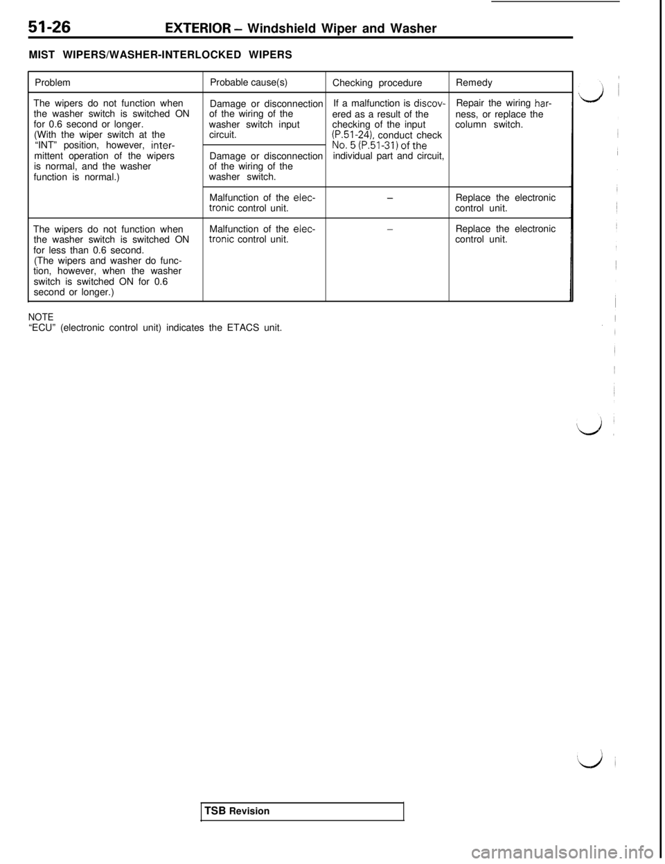
MIST WIPERS/WASHER-INTERLOCKED WIPERS
ProblemProbable cause(s)
Checking procedureRemedy
The wipers do not function when
the washer switch is switched ONDamage or disconnectionIf a malfunction is discov-
of the wiring of the
ered as a result of theRepair the wiring
har-for 0.6 second or longer.
(With the wiper switch at thewasher switch input
circuit.checking of the inputness, or replace the
column switch.
“INT” position, however, inter-
mittent operation of the wipers
is normal, and the washer
function is normal.)
(P.51-241, conduct check
Damage or disconnectionNo.5(P.51-31)oftheindividual part and circuit,
of the wiring of the
washer switch.
Malfunction of the elec-tronic control unit.
-Replace the electronic
control unit.
The wipers do not function whenMalfunction of the elec-
-the washer switch is switched ONtronic control unit.Replace the electronic
for less than 0.6 second.control unit.
(The wipers and washer do func-
tion, however, when the washer
switch is switched ON for 0.6
second or longer.)
NOTE“ECU” (electronic control unit) indicates the ETACS unit.
TSB Revision
Page 965 of 1146
EXTERIOR - Windshield Wiper and Washer
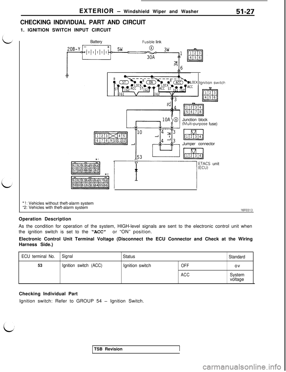
CHECKING INDIVIDUAL PART AND CIRCUIT1. IGNITION SWITCH INPUT CIRCUIT51-27
BatteryFusible link
LOCK lgnitlon switch
Junction block
(Multl-purpose fuse)
Jumper connector
i! ~~A$ unit
“I : Vehicles without theft-alarm system
“2: Vehicles with theft-alarm system16FO313
Operation Description
As the condition for operation of the system, HIGH-level signals are sent to the electronic control unit when
the ignition switch is set to the “ACC” or “ON” position.
Electronic Control Unit Terminal Voltage (Disconnect the ECU Connector and Check at the Wiring
Harness Side.)
ECU terminal No.SignalStatusStandard
53Ignition switch (ACC)Ignition switchOFFov
ACCSystem
voltageChecking Individual Part
Ignition switch: Refer to GROUP 54
- Ignition Switch.
TSB Revision
Page 966 of 1146
51-28EXTERIOR - Windshield Wiper and Washer
2. WIPER SWITCH
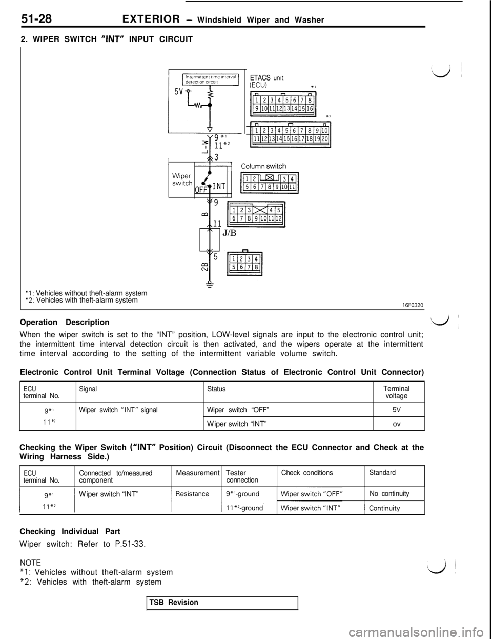
‘ANT” INPUT CIRCUIT
Iin,Ullnl,,en, ll”lC I”,CI”,IIdctcclion CIICUI,
5v
i-i
7 ;;:2
A3II--
ETACS unrt‘,ij I
Wrperswitch
Lolumn switch
” J/B
“I : Vehicles without theft-alarm system“2: Vehicles with theft-alarm system16FO320
Operation Description
L+,When the wiper switch is set to the “INT” position, LOW-level signals are input to the electronic control unit;
the intermittent time interval detection circuit is then activated, and the wipers operate at the intermittent
time interval according to the setting of the intermittent variable volume switch.
Electronic Control Unit Terminal Voltage (Connection Status of Electronic Control Unit Connector)
ECUterminal No.
9”’
1 1 *2
Signal
Wiper switch “INT” signalStatus
Wiper switch “OFF”Wiper switch “INT”
Terminal
voltage
5Vov
Checking the Wiper Switch
(“INT” Position) Circuit (Disconnect the ECU Connector and Check at the
Wiring Harness Side.)
ECUConnected to/measured
terminal No.componentMeasurement TesterconnectionCheck conditionsStandardWiper switch “INT”
No continuityChecking Individual Part
Wiper switch: Refer to
P.51-33.
NOTE
*l : Vehicles without theft-alarm system
“2: Vehicles with theft-alarm system
TSB Revision
Page 967 of 1146
EXTERIOR - Windshield Wiper and Washer
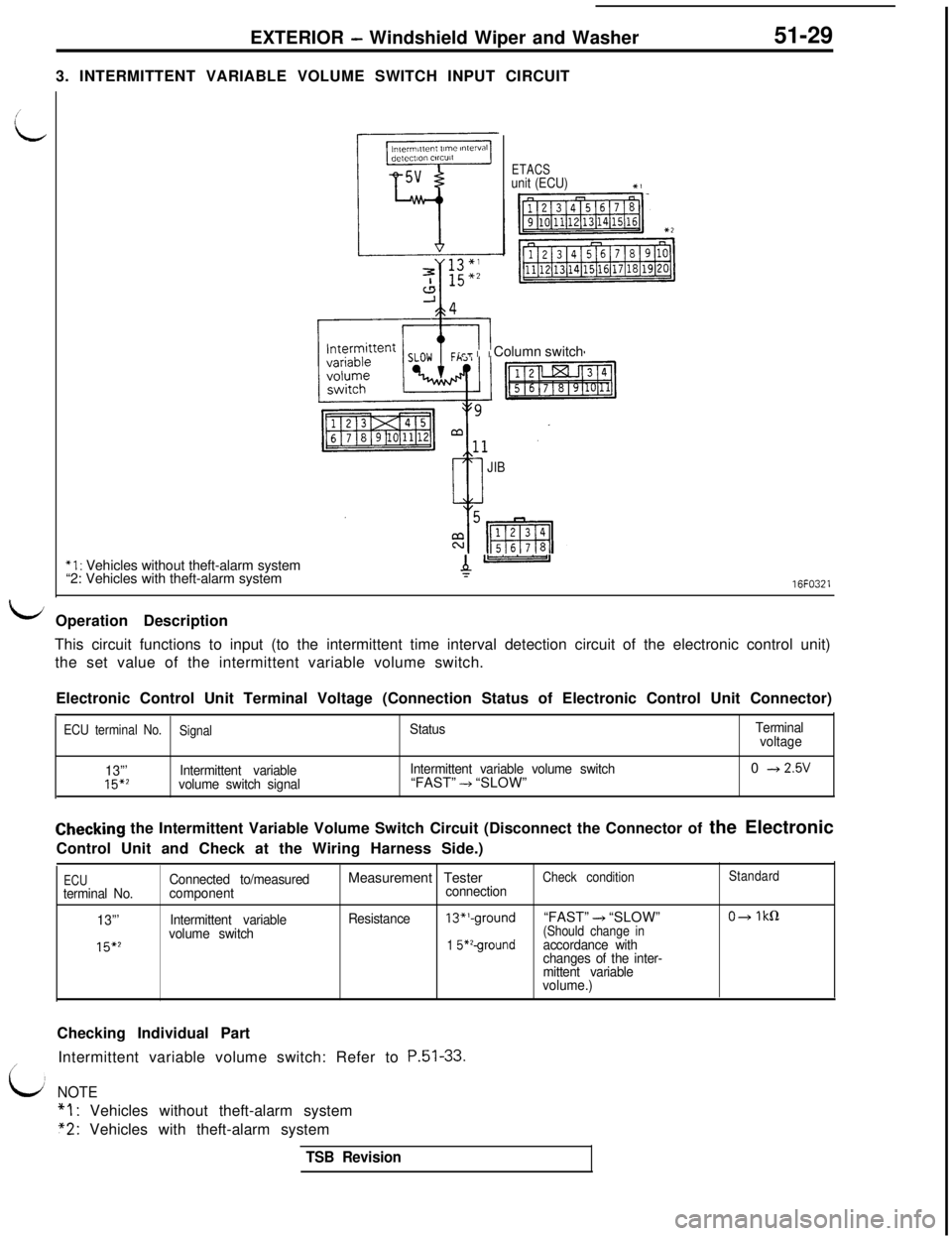
3. INTERMITTENT VARIABLE VOLUME SWITCH INPUT CIRCUIT51-29
ETACSunit (ECU)Xi
i-7 II Column switch
JIB
*l : Vehicles without theft-alarm system
“2: Vehicles with theft-alarm systemA-16FO321
eiOperation Description
This circuit functions to input (to the intermittent time interval detection circuit of the electronic control unit)
the set value of the intermittent variable volume switch.
Electronic Control Unit Terminal Voltage (Connection Status of Electronic Control Unit Connector)
ECU terminal No.
SignalStatusTerminal
voltage
13”’
15*2Intermittent variable
volume switch signalIntermittent variable volume switch“FAST” -+ “SLOW”0 + 2.5V
Checking the Intermittent Variable Volume Switch Circuit (Disconnect the Connector of the Electronic
Control Unit and Check at the Wiring Harness Side.)
ECUterminal No.
13”’
15*2
Connected to/measured
component
Intermittent variable
volume switchMeasurement TesterCheck conditionStandardconnection
Resistance
13*‘-ground“FAST” + “SLOW”O+ IkS1(Should change in
1 S*‘-groundaccordance with
changes of the inter-
mittent variable
volume.)Checking Individual Part
Intermittent variable volume switch: Refer to
P.51-33./
idNOTE
“1: Vehicles without theft-alarm system
“2: Vehicles with theft-alarm system
TSB Revision
Page 968 of 1146
51-30
EXTERIOR - Windshield Wiper and Washer
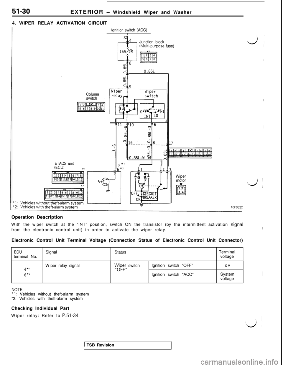
4. WIPER RELAY ACTIVATION CIRCUIT
Columnswitch
ETACS untt(ECU) t,
lgnttton switch (ACC)I
Junction block(Multi-purpose fuse)0.85L
*11 $0J\
i?+”
coii
aIt
0.85L-W dA
*’II16FO322
Wiper
motor
Ei
123 4
Operation Description
With the wiper switch at the “INT” position, switch ON the transistor (by the intermittent activation signal
from the electronic control unit) in order to activate the wiper relay.
Electronic Control Unit Terminal Voltage (Connection Status of Electronic Control Unit Connector)
ECUterminal No.SignalStatusTerminal
voltage
4”’
6*2Wiper relay signal)N$Fy switch
I,Ignition switch “OFF”
Ignition switch “ACC”ov
System
voltage
NOTE“I : Vehicles without theft-alarm system
“2: Vehicles with theft-alarm system
Checking Individual Part
Wiper relay: Refer to
P.51-34.
Lj 1
I
I
I
I
‘d ’1
I
\ ~
1 TSB Revision
Page 969 of 1146
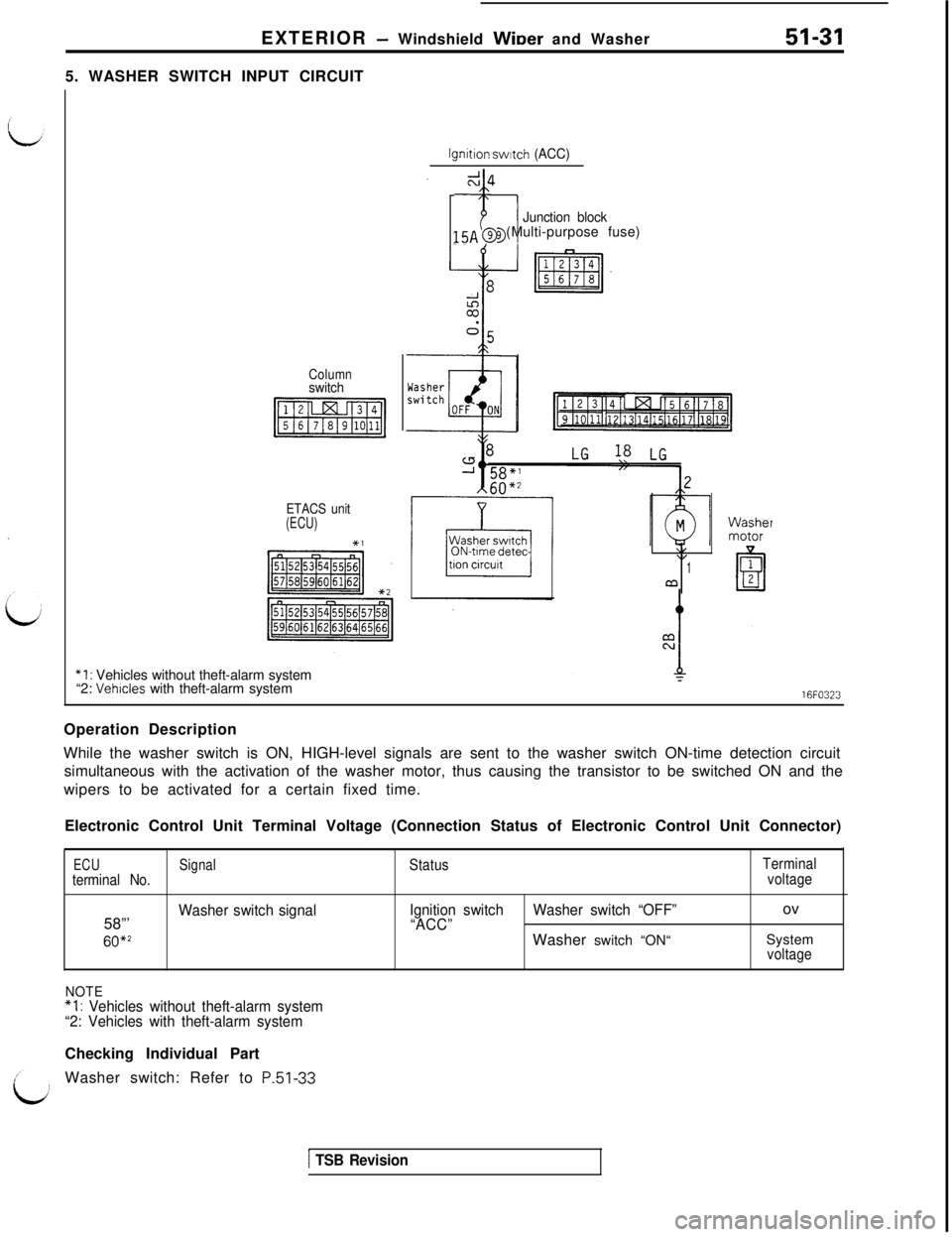
EXTERIOR - Windshield WiDer and Washer51-315. WASHER SWITCH INPUT CIRCUIT
lgnitlon swatch (ACC)
Columnswitch
ETACS unit(ECU)*,
-7-l
Junction block15~ @ (Multi-purpose fuse)
ON-time detec-\I\I1a
“I : Vehicles without theft-alarm system
“2: Vehicles with theft-alarm system16FO323
Operation Description
While the washer switch is ON, HIGH-level signals are sent to the washer switch ON-time detection circuit
simultaneous with the activation of the washer motor, thus causing the transistor to be switched ON and the
wipers to be activated for a certain fixed time.
Electronic Control Unit Terminal Voltage (Connection Status of Electronic Control Unit Connector)
ECUterminal No.58”’
60*2Signal
Washer switch signal
Status
Ignition switch
“ACC”Washer switch “OFF”Washer switch “ON“
Terminal
voltageov
System
voltage
NOTE*I : Vehicles without theft-alarm system
“2: Vehicles with theft-alarm systemChecking Individual Part
Washer switch: Refer to
P.51-33
1 TSB Revision
Page 970 of 1146
EXTERIOR - Windshield Wiper and Washer
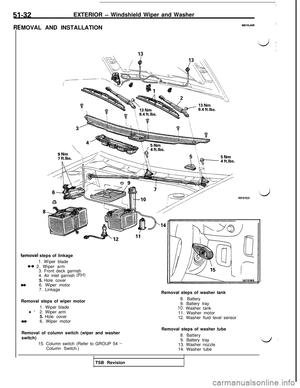
MOVAL AND INSTALLATIONY5lK.JAR
I
‘LJ (
I
\
9Nm7 ft.lbs.
3emoval steps of linkage
I. Wiper blade
I)* 2. Wiper arm
3. Front deck garnish
4. Air inlet garnish
(RH)5. Hole cover
a*6. Wiper motor16FO103
7. Linkage
Removal steps of wiper motor
1. Wiper blade
l *2. Wiper arm
5. Hole cover
*I)6. Wiper motorRemoval steps of washer tank
8. Battery
9. Battery tray
10. Washer tank
11. Washer motor
12. Washer fluid level sensor
Removal of column switch (wiper and washer
switch)
15. Column switch (Refer to GROUP 54
-Column Switch.)
TSB RevisionRemoval steps of washer tube
8. Battery
9. Battery tray
13. Washer nozzle
14. Washer tube