MITSUBISHI 3000GT 1991 Service Manual
3000GT 1991
MITSUBISHI
MITSUBISHI
https://www.carmanualsonline.info/img/19/57085/w960_57085-0.png
MITSUBISHI 3000GT 1991 Service Manual
Trending: oil capacities, radiator cap, service reset, change time, run flat, open hood, oil level
Page 991 of 1146
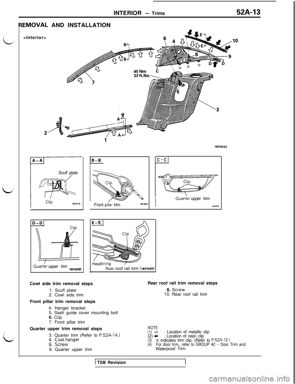
INTERIOR - Trims52A-13EMOVAL AND INSTALLATION
19FOO33
Scuff plate
D-D1Quart&
upper trim19FOO2C
1B-B
Front piiar trimc-cIQuart&
upper trim
,wca*
Rear roof rail trim 1 igFoo22Cowl side trim removal steps
1. Scuff plate
2. Cowl side trim
Front pillar trim removal steps
4. Hanger bracket
5. Sash guide cover mounting bolt
6. Clip
7. Front pillar trimRear roof rail trim removal steps
8. Screw
10. Rear roof rail trim
Quarter upper trim removal steps
3. Quarter trim (Refer to
P.52A-14.)48: ;;;;anger9. Quarter upper trim
1 TSB Revision
NOTE(1) @: Location of metallic clip(2) c: Location of resin clip(3)* indicates trim clip. (Refer to P.52A-12.)(4)For door trim,. refer to GROUP 42 - Door TrimandWaterproof Film.
I
Page 992 of 1146
52A-14
INTERIOR - Trims
Scuff plate
19FOO46
33 ftlbs.19FOl60
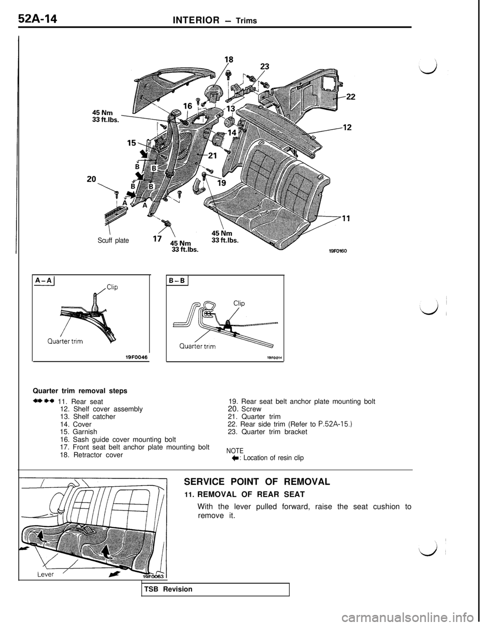
Quarter trim removal steps
** ** 11. Rear seat
12. Shelf cover assembly
13. Shelf catcher
14. Cover
15. Garnish19. Rear seat belt anchor plate mounting bolt
20. Screw
21. Quarter trim
22. Rear side trim (Refer to
P.52A-15.)23. Quarter trim bracket
16. Sash guide cover mounting bolt
17. Front seat belt anchor plate mounting bolt
18. Retractor cover
NOTE*: Location of resin clipSERVICE POINT OF REMOVAL
11. REMOVAL OF REAR SEAT
With the lever pulled forward, raise the seat cushion to
remove it.
TSB Revision
Page 993 of 1146
INTERIOR - Trims52A-15
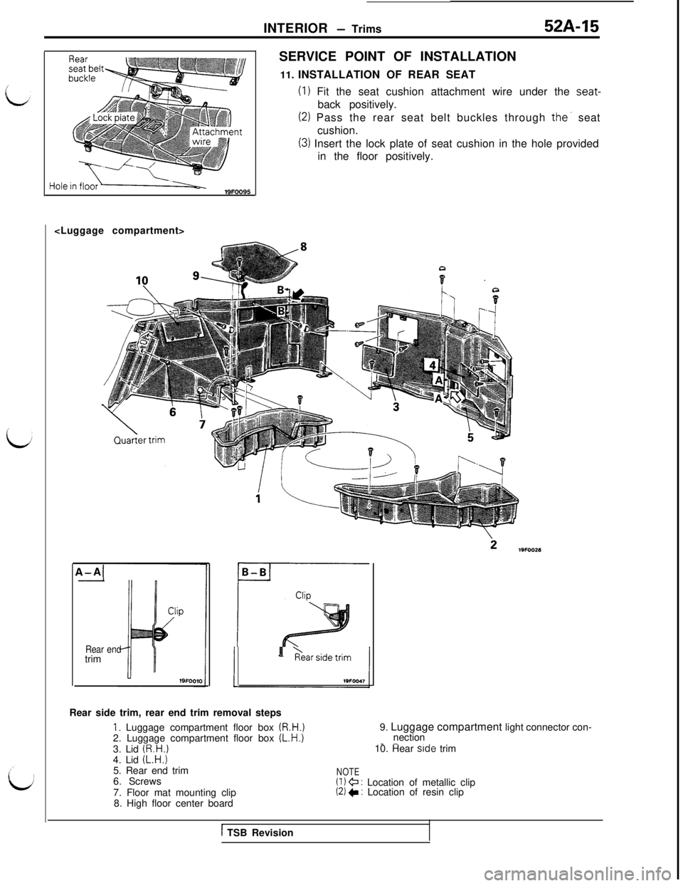
ISERVICE POINT OF INSTALLATION
11. INSTALLATION OF REAR SEAT
(1) Fit the seat cushion attachment wire under the seat-back positively.
(2) Pass the rear seat belt buckles through the. seat
cushion.
(3) Insert the lock plate of seat cushion in the hole provided
in the floor positively.
4-A{-
Rear endtrimB-Br-Rear side trim, rear end trim removal steps
I. Luggage compartment floor box (R.H.)2. Luggage compartment floor box (L.H.)9. Luggage compartment light connector con-
nection_ -10. Hear side trim
NOTE(1) @ : Location of metallic clip(2) * : Location of resin clip 3. Lid
(R.H.)4. Lid (L.H.)5. Rear end trim
6. Screws
7. Floor mat mounting clip
8. High floor center board
1 TSB Revision
Page 994 of 1146
52A-16INTERIOR
- Trims
A-AIB-B[
1Liftgate lower trim
Clip
Liftgate lower trim
D-D
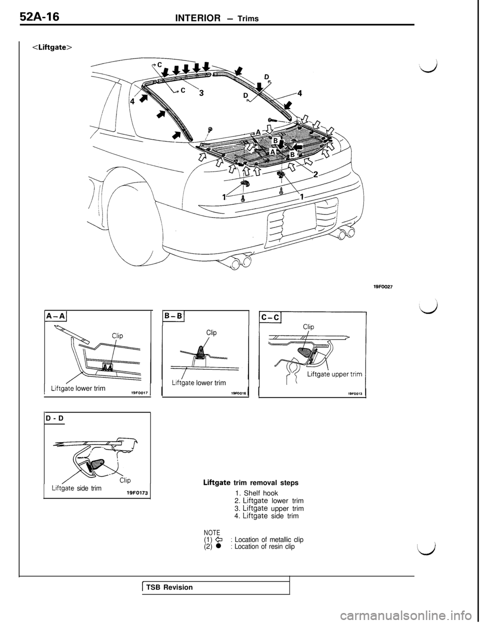
Liftbate side trim19FO173Liftgate trim removal steps
1. Shelf hook
2.
Liftgate lower trim
3. Liftgate upper trim
4. Liftgate side trim
19FOO27
NOTE(1) @: Location of metallic clip(2) l: Location of resin clip
1 TSB Revision
Page 995 of 1146
L
LINTERIOR
- Headlining52A-17
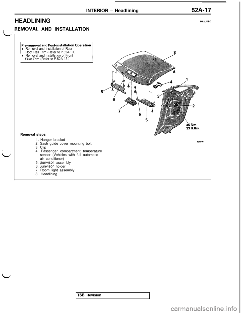
HEADLININGM52lJDBC[EMOVAL AND INSTALLATION
Pre-removal and Post-installation Operationl Removal and Installation of Rear
Roof Rail Trim (Refer to P52A-13.)l Removal and lnstallatron of FrontPillarTrim (Refer to P.52A-13.)Removal steps
1. Hanger bracket
2. Sash guide cover mounting bolt
3. Clip
4. Passenger compartment temperature
sensor (Vehicles with full automatic
air conditioner)
5. Sunvisor assembly
6. Sunvisor holder
7. Room light assembly
8. HeadliningTSB Revision
Page 996 of 1146
52A-18INTERIOR - Front Seat
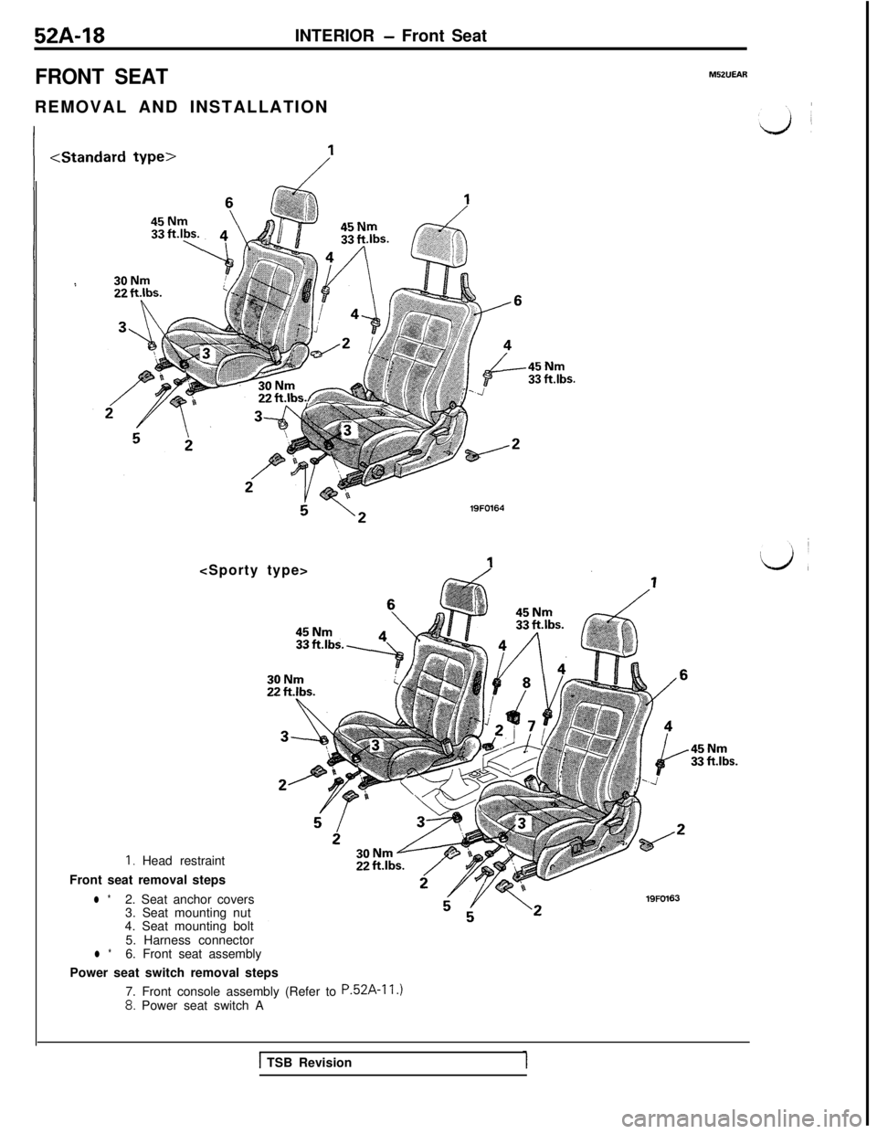
FRONT SEATREMOVAL AND INSTALLATION
-45 Nm33 ftlbs.
s \*lSFO164
I. Head restraint
Front seat removal steps
l *2. Seat anchor covers
3. Seat mounting nut
4. Seat mounting bolt
5. Harness connector
l *6. Front seat assembly
Power seat switch removal steps
7. Front console assembly (Refer to
P.52A-11.)8. Power seat switch A
lSFOI63
M52UEAR.45Nm
33 ftlbs.
1 TSB Revision
Page 997 of 1146
INTERIOR - Front Seat52A-19INSPECTION
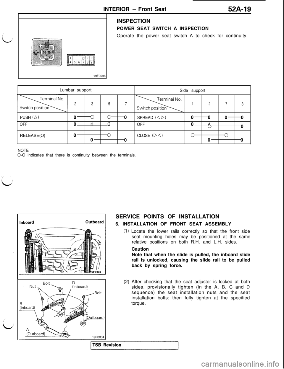
POWER SEAT SWITCH A INSPECTION
Operate the power seat switch A to check for continuity.
,19FOO9lLumbar support
Side support
23571278
PUSH (A,0300SPREAD (4D)00
00
OFF0n0OFF0A”0
RELEASE(O)0
0CLOSE (D 4)000
000
NOTEO-O indicates that there is continuity between the terminals.
InboardOutboard19FOO34SERVICE POINTS OF INSTALLATION
6. INSTALLATION OF FRONT SEAT ASSEMBLY
(I) Locate the lower rails correctly so that the front side
seat mounting holes may be positioned at the same
relative positions on both R.H. and L.H. sides.
Caution
Note that when the slide is pulled, the inboard slide
rail is unlocked, causing the slide rail to be pulled
back by spring force.
(2) After checking that the seat adjuster is locked at both
sides, provisionally tighten (in the A, B, C and D
sequence) the seat installation nuts and the seat
installation bolts; then fully tighten at the specified
torque.
Page 998 of 1146
52A-20INTERIOR - Front Seat
ont seat forward
lnstallatlon bracket
Forward tab
:iA - A cross sectionlSFOO44
Rear(outboard)Claw
Hole
lSFOOC4
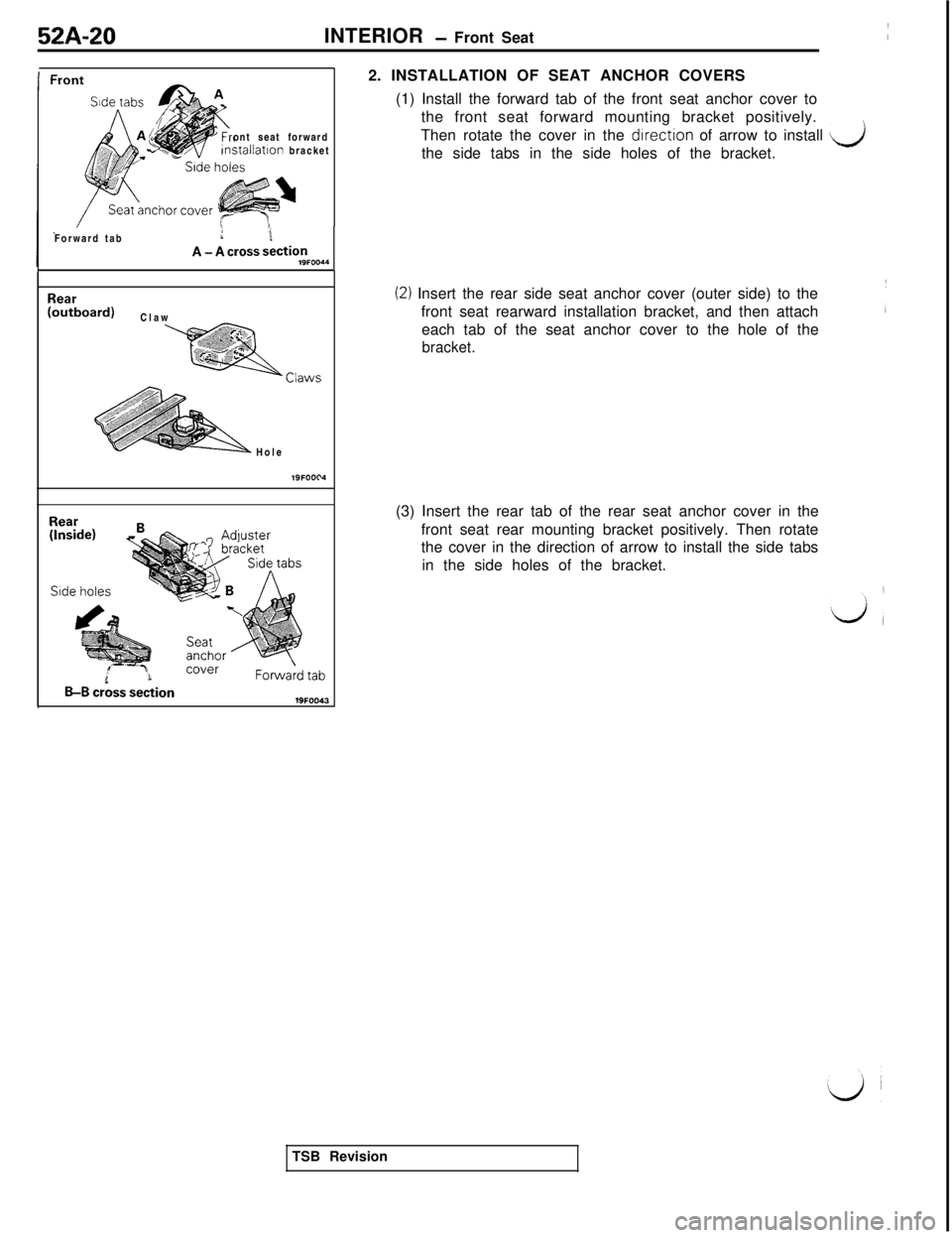
B-B crbss section2. INSTALLATION OF SEAT ANCHOR COVERS
(1) Install the forward tab of the front seat anchor cover to
the front seat forward mounting bracket positively.
Then rotate the cover in the drrection of arrow to install
dthe side tabs in the side holes of the bracket.
(2) Insert the rear side seat anchor cover (outer side) to the
front seat rearward installation bracket, and then attach
each tab of the seat anchor cover to the hole of the
bracket.(3) Insert the rear tab of the rear seat anchor cover in the
front seat rear mounting bracket positively. Then rotate
the cover in the direction of arrow to install the side tabs
in the side holes of the bracket.
TSB Revision
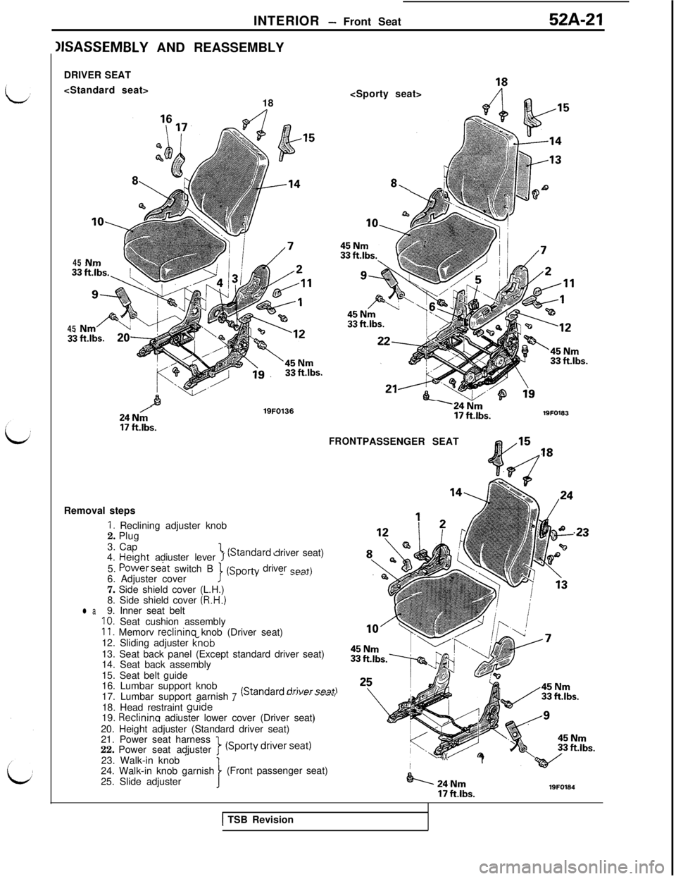
Page 999 of 1146
INTERIOR - Front Seat52A-21
IISASSEMBLY AND REASSEMBLY
DRIVER SEAT
18
8,‘(-i
Q45
Nm45
NmP
ii filbs.20-7;s
I24 Nm17 ftlbs.19FO18324N;17 ftlbs.
19FO136
FRONTPASSENGER SEAT18
.23Removal stepsI. Reclining adjuster knob
2. Plug
3. Cap
1“+Qnrl~rrl driver seat)
4. Height adiuster lever I v~““~‘” L5.
POtier S&t switch B
6. Adjuster cover(Sporty driver sent)-- - - . ,7. Side shield cover (L.H.)
8. Side shield cover
(R.H.)l a9. Inner seat beltIO. Seat cushion assembly11. Memorv reclinina knob (Driver seat)
12. Sliding adjuster (nob13. Seat back panel (Except standard driver seat)
14. Seat back assembly
15. Seat belt guide
16. Lumbar support knob
17. Lumbar support aarnish
7(Stand& dri\mr
-19. Reclinina adiuster lower cover (Driver seat)
20. Height adjuster (Standard driver seat)
21. Power seat harness
22. Power seat adjuster1
(SporVdrivr----”23. Walk-in knob
’’--4X-1
24. Walk-in knob garnish
25. Slide adjuster(Front passenger seat)24Nm
171, Ihc19FO184
1 TSB Revision
Page 1000 of 1146
52A-22
INTERIOR - Front Seat
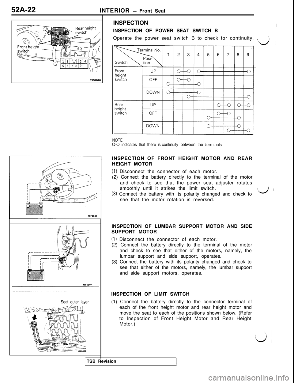
INSPECTION
INSPECTION OF POWER SEAT SWITCH B
Operate the power seat switch B to check for continuity. ,
)
Seat outer layer123456789
NOTEO-O indicates that there IS continuity between the terminalsINSPECTION OF FRONT HEIGHT MOTOR AND REAR
HEIGHT MOTOR
(1) Disconnect the connector of each motor.
(2) Connect the battery directly to the terminal of the motor
and check to see that the power seat adjuster rotates
smoothly until it strikes the limit switch.
(3) Connect the battery with its polarity changed and check to\d Isee that the motor rotation is reversed.
TSB Revision
1INSPECTION OF LUMBAR SUPPORT MOTOR AND SIDE
SUPPORT MOTOR
(I) Disconnect the connector of each motor.
(2) Connect the battery directly to the terminal of the motor
and check to see that either of the motors, namely, the
lumbar support and side support, operates.
(3) Connect the battery with its polarity changed and check to
see that either of the motors, namely, the lumbar support
and side support motors, operates.
INSPECTION OF LIMIT SWITCH
(1) Connect the battery directly to the connector terminal of
each of the front height motor and rear height motor and
move the seat to each of the positions shown below. (Refer
to Inspection of Front Height Motor and Rear Height
Motor.)
Trending: gearbox, maintenance schedule, recommended oil, washer fluid, child seat, jacking, fuel type
