MITSUBISHI 3000GT 1991 Service Manual
Manufacturer: MITSUBISHI, Model Year: 1991, Model line: 3000GT, Model: MITSUBISHI 3000GT 1991Pages: 1146, PDF Size: 76.68 MB
Page 1071 of 1146
SUPPLEMENTAL RESTRAINT SYSTEM (SRS) -SRS Diagnosis Unit (SDU) 52B-611330721
13R072i
ht-----
SERVICE POINTS OF INSTALLATION
PRE-INSTALLATION INSPECTIONBefore SRS diagnosis unit is installed in the vehicle, it must be
visually inspected. If a dent, crack or other deformation is
detected, discard the SRS diagnosis unit and replace it with a
new one that passes the visual inspection.
6. INSTALLATION OF SRS DIAGNOSIS UNIT
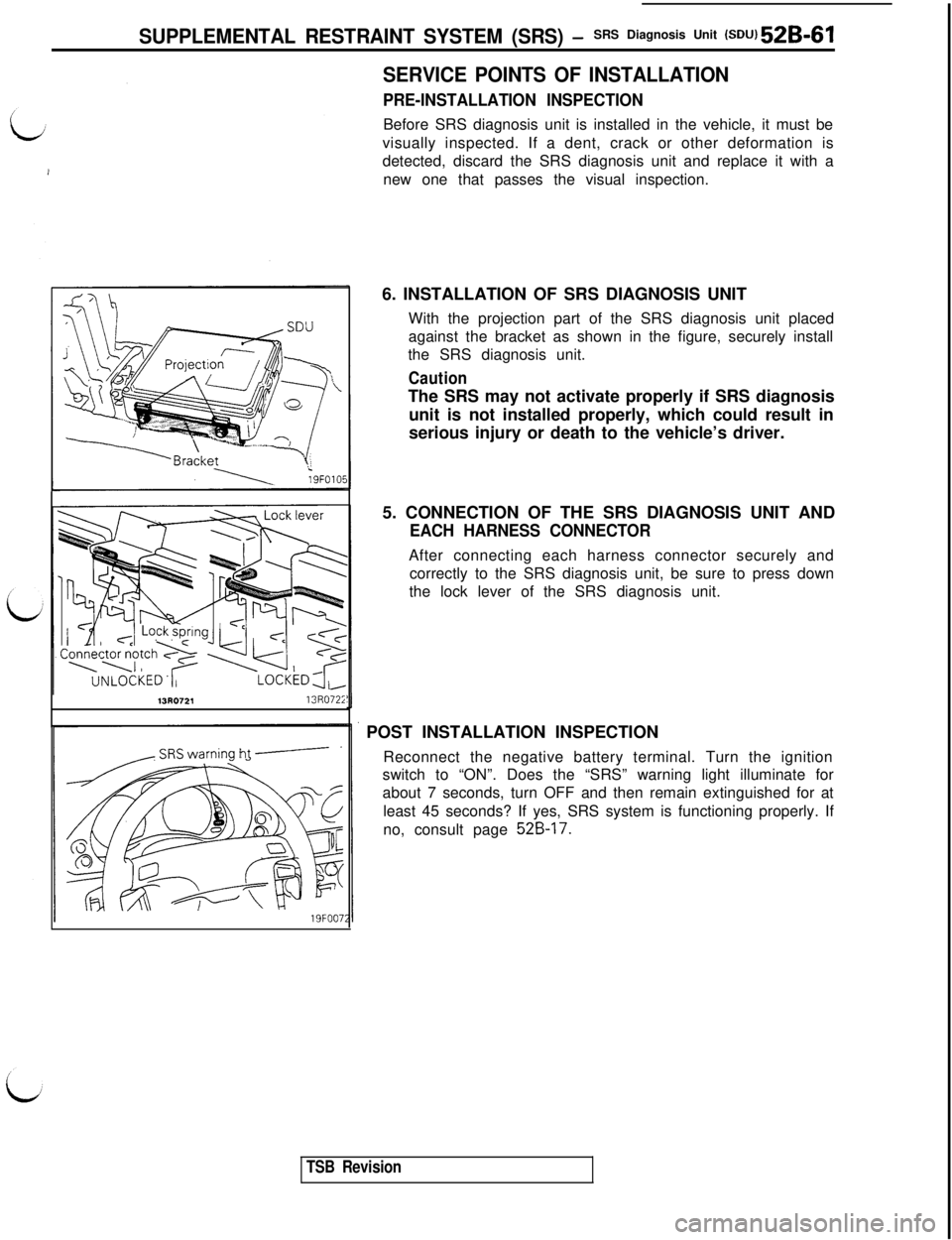
With the projection part of the SRS diagnosis unit placed
against the bracket as shown in the figure, securely install
the SRS diagnosis unit.
CautionThe SRS may not activate properly if SRS diagnosis
unit is not installed properly, which could result in
serious injury or death to the vehicle’s driver.
5. CONNECTION OF THE SRS DIAGNOSIS UNIT AND
EACH HARNESS CONNECTORAfter connecting each harness connector securely and
correctly to the SRS diagnosis unit, be sure to press down
the lock lever of the SRS diagnosis unit.
POST INSTALLATION INSPECTION
Reconnect the negative battery terminal. Turn the ignition
switch to “ON”. Does the “SRS” warning light illuminate for
about 7 seconds, turn OFF and then remain extinguished for at
least 45 seconds? If yes, SRS system is functioning properly. If
no, consult page
52B-17.
TSB Revision
Page 1072 of 1146
52B-62Air Bag ModuleSUPPLEMENTAL RESTRAINT SYSTEM (SRS) - and Clock Spring
AIR BAG MODULE AND CLOCK SPRINGM52PDCA
Caution1. Never attempt to disassemble or repair the
air bag module or clock spring.
If faulty, replace it.
2. Do not drop the air bag module or clock
spring or allow contact with water, grease or
oil.Replace it if a dent, crack, deformation or
rust are detected.
3.The air bag module should be stored on a flat
surface and placed so that the pad surface isfacing upward.
REMOVAL AND INSTALLATION1
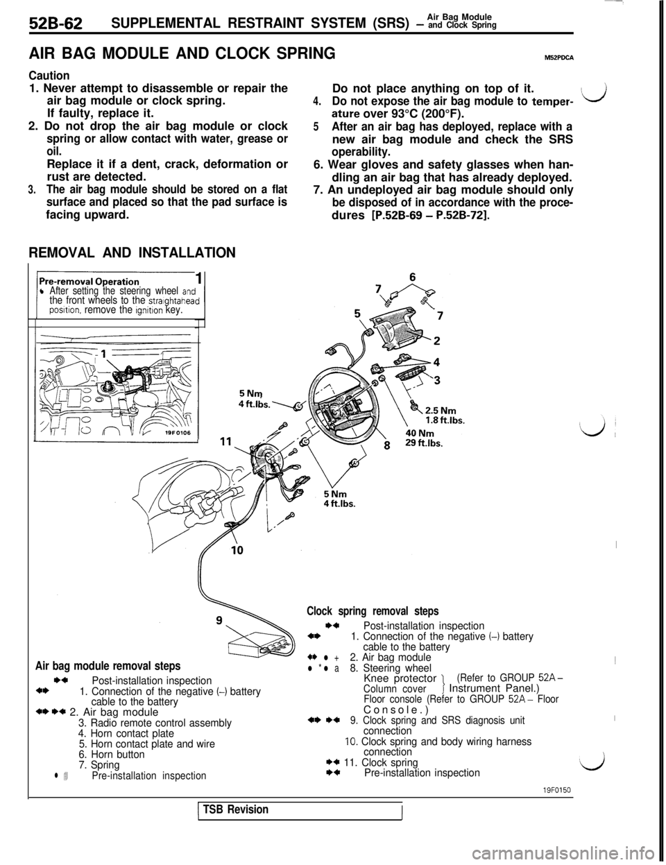
l After setting the steering wheel antthe front wheels to the stralghtaheaposltion. remove the ignition key.5NmDo not place anything on top of it.
4.Do not expose the air bag module to temper-ILJ
ature over 93°C (200°F).
5After an air bag has deployed, replace with anew air bag module and check the SRS
operability.6. Wear gloves and safety glasses when han-
dling an air bag that has already deployed.
7. An undeployed air bag module should only
be disposed of in accordance with the proce-dures
[P.52B-69 - P.52B-721.
Air bag module removal stepsI)4
Post-installation inspection4*1. Connection of the negative (-1 battery
cable to the battery
*I) I)* 2. Air bag module3. Radio remote control assembly
4. Horn contact plate
5. Horn contact plate and wire
6. Horn button
7. Spring
l 4Pre-installation inspection
Clock spring removal steps
I)4Post-installation inspection4*1. Connection of the negative (-1 battery
cable to the battery
+* l +2. Air bag modulel * l a8. Steering wheelKnee protector 1(Refer to GROUP 52A-
Column coverJ Instrument Panel.)Floor console (Refer to GROUP 52A- FloorConsole.)
*I) *+9. Clock spring and SRS diagnosis unitconnection10. Clock spring and body wiring harness
connection
I)* 11. Clock springI)4Pre-installation inspection
I1
I
‘d
1 TSB Revision
19FO150
III
Page 1073 of 1146
Air Bag ModuleSUPPLEMENTAL RESTRAINT SYSTEM (SRS) - and Clock Spring526-6319FOlll
3
SERVICE POINTS OF REMOVAL1. DISCONNECTION OF THE NEGATIVE (-) BATTERY
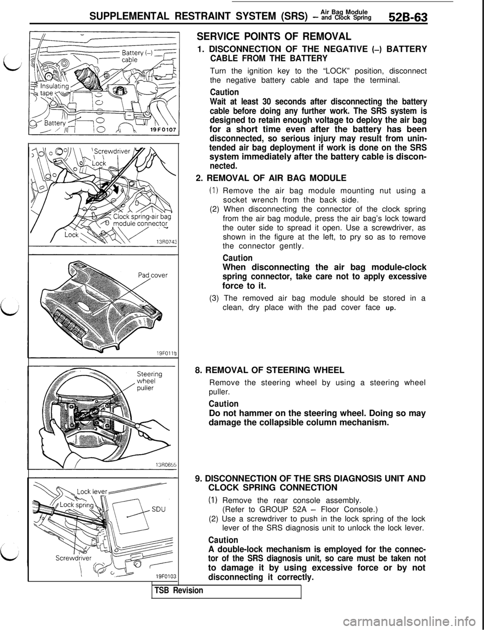
CABLE FROM THE BATTERYTurn the ignition key to the “LOCK” position, disconnect
the negative battery cable and tape the terminal.
Caution
Wait at least 30 seconds after disconnecting the battery
cable before doing any further work. The SRS system is
designed to retain enough voltage to deploy the air bagfor a short time even after the battery has been
disconnected, so serious injury may result from unin-
tended air bag deployment if work is done on the SRSsystem immediately after the battery cable is discon-
nected.2. REMOVAL OF AIR BAG MODULE
(1) Remove the air bag module mounting nut using a
socket wrench from the back side.
(2) When disconnecting the connector of the clock spring
from the air bag module, press the air bag’s lock toward
the outer side to spread it open. Use a screwdriver, as
shown in the figure at the left, to pry so as to remove
the connector gently.
CautionWhen disconnecting the air bag module-clock
spring connector, take care not to apply excessiveforce to it.
(3) The removed air bag module should be stored in a
clean, dry place with the pad cover face up.
8. REMOVAL OF STEERING WHEEL
Remove the steering wheel by using a steering wheel
puller.
CautionDo not hammer on the steering wheel. Doing so may
damage the collapsible column mechanism.
9. DISCONNECTION OF THE SRS DIAGNOSIS UNIT AND
CLOCK SPRING CONNECTION
(1) Remove the rear console assembly.
(Refer to GROUP 52A
- Floor Console.)
(2) Use a screwdriver to push in the lock spring of the lock
lever of the SRS diagnosis unit to unlock the lock lever.
Caution
A double-lock mechanism is employed for the connec-
tor of the SRS diagnosis unit, so care must be taken notto damage it by using excessive force or by not
disconnecting it correctly.
TSB Revision
Page 1074 of 1146
52B-64Air Eag Module
SUPPLEMENTAL RESTRAINT SYSTEM (SRS) - and Clock SpringConnector note
\\ I,
13R072113R0722
Air
b\“g module \(3) Remove the
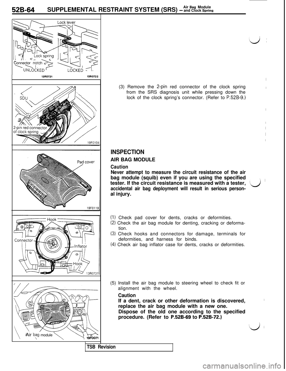
2-pin red connector of the clock spring
from the SRS diagnosis unit while pressing down the
lock of the clock spring’s connector. (Refer to
P.52B-9.)
INSPECTIONAIR BAG MODULE
Caution
Never attempt to measure the circuit resistance of the airbag module (squib) even if you are using the specified
tester. If the circuit resistance is measured with a tester,
accidental air bag deployment will result in serious person-al injury.
(1) Check pad cover for dents, cracks or deformities.
(2) Check the air bag module for denting, cracking or deforma-
tion.
(3) Check hooks and connectors for damage, terminals for
deformities, and harness for binds.
(4) Check air bag inflator case for dents, cracks or deformities.
TSB Revision(5) Install the air bag module to steering wheel to check fit or
alignment with the wheel.
CautionIf a dent, crack or other deformation is discovered,
replace the air bag module with a new one.
Dispose of the old one according to the specified
procedure. (Refer to
P52B-69 to P.52B-72.)
I
I
I
I
I
I
I
’ I
‘Lj
I
‘iJ i
Page 1075 of 1146
Air Bag ModuleSUPPLEMENTAL RESTRAINT SYSTEM (SRS) - and Clock Spring52B-65To SRS diagnosis unit
19FO101
i
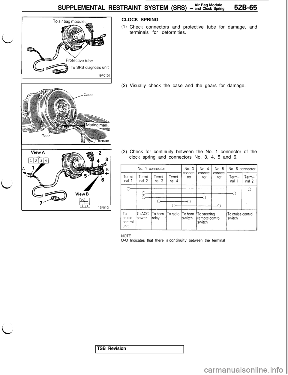
LJLJ19FOlOSCLOCK SPRING
(I) Check connectors and protective tube for damage, and
terminals for deformities.
(2) Visually check the case and the gears for damage.
(3) Check for continuity between the No. 1 connector of the
clock spring and connectors No. 3, 4, 5 and 6.
NOTEO-O Indicates that there IS continuity between the terminal
TSB Revision
Page 1076 of 1146
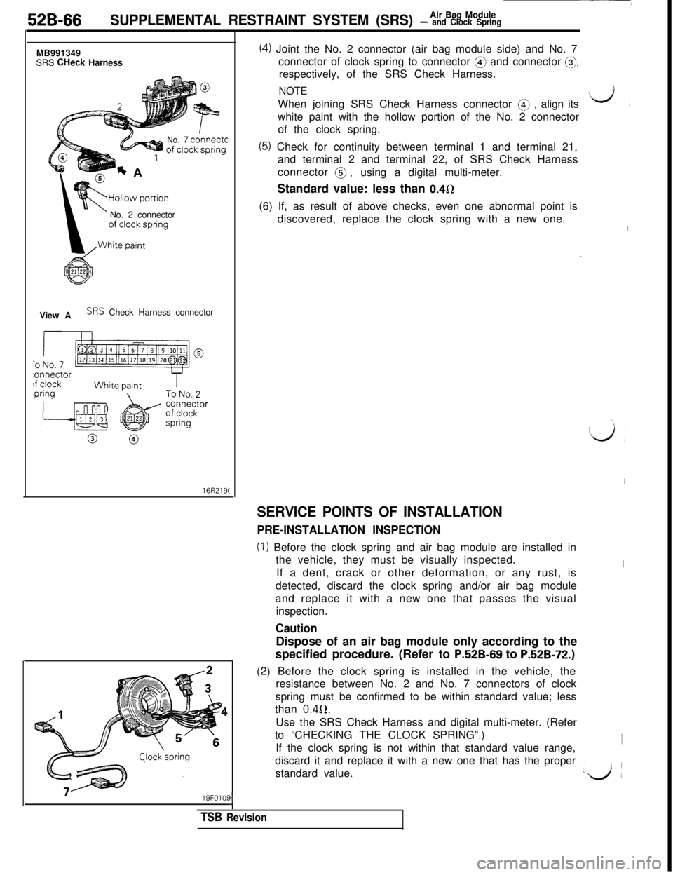
52B-66Air Bag ModuleSUPPLEMENTAL RESTRAINT SYSTEM (SRS) - and Clock SpringMB991349
SRS CHeck Harness
No.7 connectcNo. 2 connector
View A
SRS Check Harness connector
16R219C
19FOlO!I
TSB Revision
(4) Joint the No. 2 connector (air bag module side) and No. 7
connector of clock spring to connector @ and connector
@,respectively, of the SRS Check Harness.
NOTEWhen joining SRS Check Harness connector
(4) , align its
white paint with the hollow portion of the No. 2 connector
of the clock spring.
(5) Check for continuity between terminal 1 and terminal 21,
and terminal 2 and terminal 22, of SRS Check Harness
connector @ ,
using a digital multi-meter.
Standard value: less than
0.452(6) If, as result of above checks, even one abnormal point is
discovered, replace the clock spring with a new one.
SERVICE POINTS OF INSTALLATION
PRE-INSTALLATION INSPECTION
(I) Before the clock spring and air bag module are installed in
the vehicle, they must be visually inspected.
If a dent, crack or other deformation, or any rust, is
detected, discard the clock spring and/or air bag module
and replace it with a new one that passes the visual
inspection.
CautionDispose of an air bag module only according to the
specified procedure. (Refer to
P.52B-69 to P.52B-72.)(2) Before the clock spring is installed in the vehicle, the
resistance between No. 2 and No. 7 connectors of clock
spring must be confirmed to be within standard value; less
than
0.4(2.Use the SRS Check Harness and digital multi-meter. (Refer
to “CHECKING THE CLOCK SPRING”.)
If the clock spring is not within that standard value range,
discard it and replace it with a new one that has the proper
standard value.
d:
I
\
‘d :
I
I
I
LA
Page 1077 of 1146
Air Bag Module
SUPPLEMENTAL RESTRAINT SYSTEM (SRS) - and Clock Spring52B-67Multi-use Testkr
ROM pack
(MB991 341)(MB991 359)
Diagnosis/
service
data
oumutGround
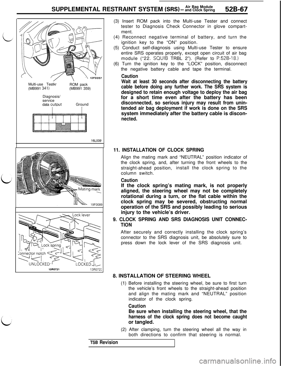
16LOO9'(3) Insert ROM pack into the Multi-use Tester and connect
tester to Diagnosis Check Connector in glove compart-
ment.
(4) Reconnect negative terminal of battery, and turn the
ignition key to the “ON” position.
(5) Conduct self-diagnosis using Multi-use Tester to ensure
entire SRS operates properly, except open circuit of air bag
module (“22. SQUIB TRBL 2”). (Refer to
P.52B-18.)(6) Turn the ignition key to the “LOCK” position, disconnect
the negative battery cable and tape the terminal.
Caution
Wait at least 30 seconds after disconnecting the battery
cable before doing any further work. The SRS system is
designed to retain enough voltage to deploy the air bagfor a short time even after the battery has been
disconnected, so serious injury may result from unin-
tended air bag deployment if work is done on the SRSsystem immediately after the battery cable is discon-
nected.
11. INSTALLATION OF CLOCK SPRINGAlign the mating mark and “NEUTRAL” position indicator of
the clock spring, and, after turning the front wheels to the
straight-ahead position,install the clock spring to the
column switch.
CautionIf the clock spring’s mating mark, is not properly
aligned, the steering wheel may not be completely
rotational during a turn, or the flat cable within the
clock spring may be severed, obstructing normal
operation of the SRS and possibly leading to serious
injury to the vehicle’s driver.
9. CLOCK SPRING AND SRS DIAGNOSIS UNIT CONNEC-
TIONAfter securely and correctly installing the clock spring’s
connector to the SRS diagnosis unit, be absolutely sure to
press down the lock lever of the SRS diagnosis unit.
13R072113R072;8. INSTALLATION OF STEERING WHEEL
(1) Before installing the steering wheel, be sure to first turn
the vehicle’s front wheels to the straight-ahead position
and align the mating mark and “NEUTRAL” position
indicator of the clock spring.
Caution
Be sure when installing the steering wheel, that the
harness of the clock spring does not become caughtor tangled.
(2) After clamping, turn the steering wheel all the way in
both directions to confirm that steering is normal.
TSB Revision
Page 1078 of 1146
52B-68SUPPLEMENTAL RESTRAINT SYSTEM (SRS) - %%%$kgSRS warning
light
/------ r--l
I
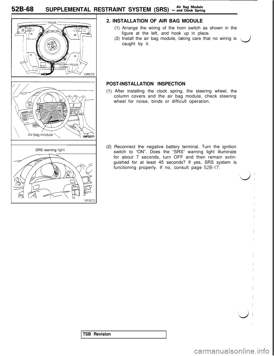
19FOO722. INSTALLATION OF AIR BAG MODULE
(1) Arrange the wiring of the horn switch as shown in the
figure at the left, and hook up in place.
(2) Install the air bag module, taking care that no wiring is
vicaught by it.
POST-INSTALLATION INSPECTION(1) After installing the clock spring, the steering wheel, the
column covers and the air bag module, check steering
wheel for noise, binds or difficult operation.
(2) Reconnect the negative battery terminal. Turn the ignition
switch to “ON”. Does the “SRS” warning light illuminate
for about 7 seconds, turn OFF and then remain extin-
guished for at least 45 seconds? If yes, SRS system is
functioning properly. If no, consult page
52B-17.
TSB Revision
Page 1079 of 1146
SUPPLEMENTAL RESTRAINT SYSTEM (SRS) - ~&%,MprOodcUures 52B-69
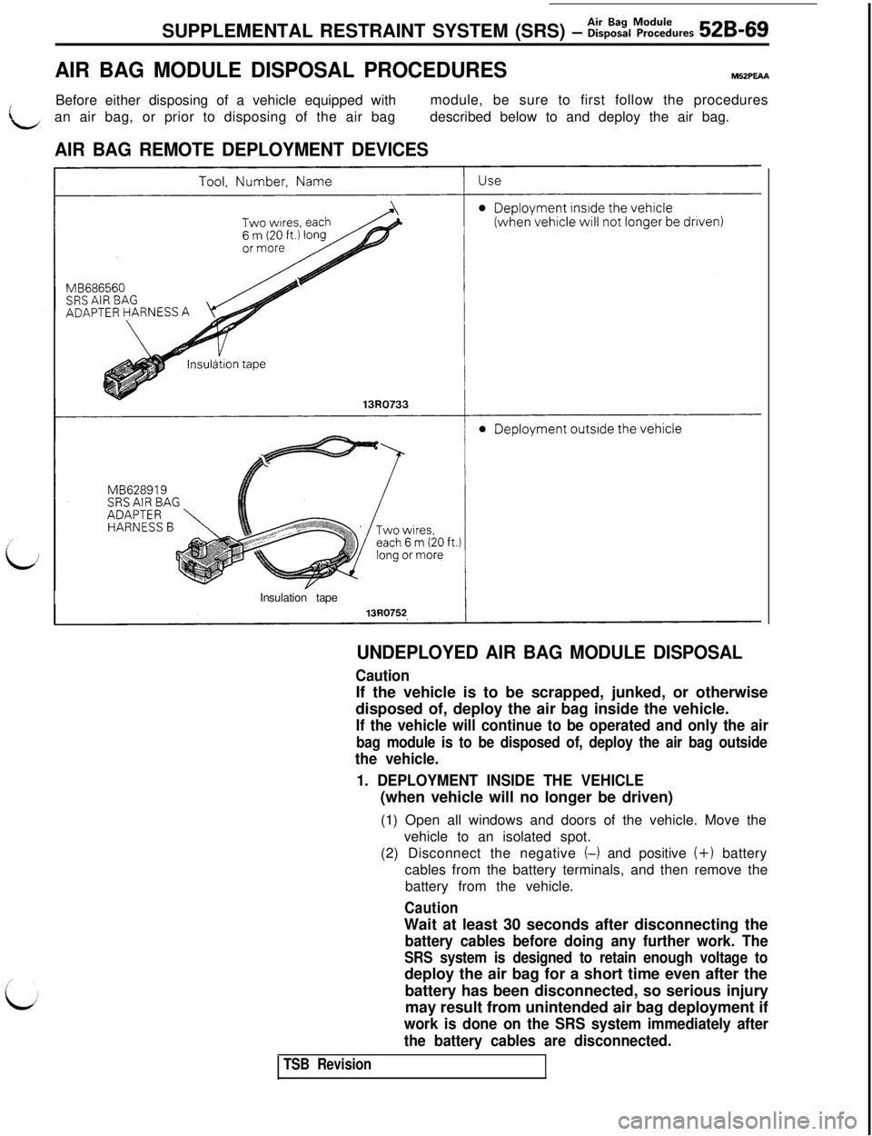
AIR BAG MODULE DISPOSAL PROCEDURESM52PmA
LBefore either disposing of a vehicle equipped withmodule, be sure to first follow the procedures
an air bag, or prior to disposing of the air bagdescribed below to and deploy the air bag.
AIR BAG REMOTE DEPLOYMENT DEVICESInsulation tape
UNDEPLOYED AIR BAG MODULE DISPOSAL
CautionIf the vehicle is to be scrapped, junked, or otherwise
disposed of, deploy the air bag inside the vehicle.
If the vehicle will continue to be operated and only the air
bag module is to be disposed of, deploy the air bag outside
the vehicle.
1. DEPLOYMENT INSIDE THE VEHICLE(when vehicle will no longer be driven)
(1) Open all windows and doors of the vehicle. Move the
vehicle to an isolated spot.
(2) Disconnect the negative
(4 and positive (i-1 battery
cables from the battery terminals, and then remove the
battery from the vehicle.
CautionWait at least 30 seconds after disconnecting the
battery cables before doing any further work. The
SRS system is designed to retain enough voltage todeploy the air bag for a short time even after the
battery has been disconnected, so serious injury
may result from unintended air bag deployment if
work is done on the SRS system immediately after
the battery cables are disconnected.
TSB Revision
Page 1080 of 1146
52B-70Air Bag ModuleSUPPLEMENTAL RESTRAINT SYSTEM (SRS) - Disposal Procedures
13R072113R0722
I
lnsulatlon
Clock\spring
connector
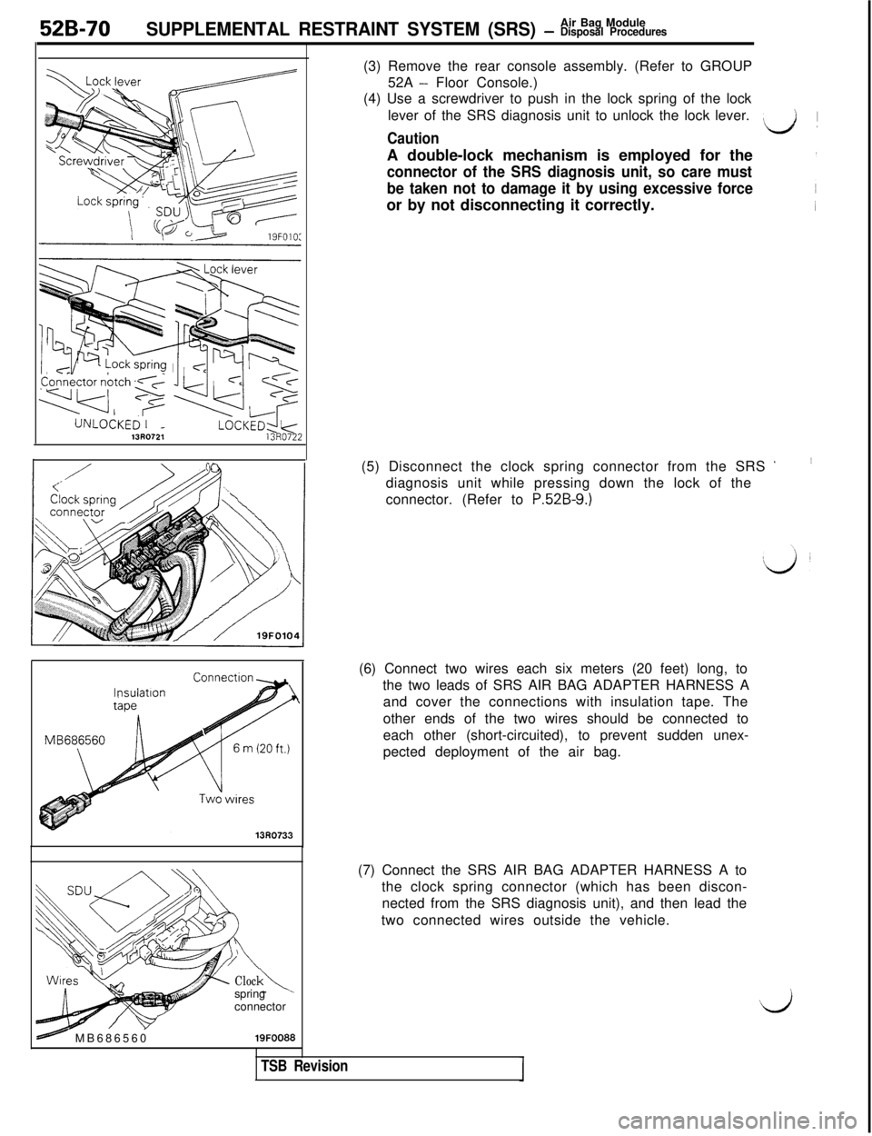
s+- MB68656019FOO88(3) Remove the rear console assembly. (Refer to GROUP
52A
- Floor Console.)
(4) Use a screwdriver to push in the lock spring of the lock
lever of the SRS diagnosis unit to unlock the lock lever.
Caution
L/! )A double-lock mechanism is employed for the
connector of the SRS diagnosis unit, so care must
be taken not to damage it by using excessive forceor by not disconnecting it correctly.
(5) Disconnect the clock spring connector from the SRS
’diagnosis unit while pressing down the lock of the
connector. (Refer to
P.52B-9.)(6) Connect two wires each six meters (20 feet) long, to
the two leads of SRS AIR BAG ADAPTER HARNESS A
and cover the connections with insulation tape. The
other ends of the two wires should be connected to
each other (short-circuited), to prevent sudden unex-
pected deployment of the air bag.
(7) Connect the SRS AIR BAG ADAPTER HARNESS A to
the clock spring connector (which has been discon-
nected from the SRS diagnosis unit), and then lead the
two connected wires outside the vehicle.
‘d
TSB Revision