MITSUBISHI 3000GT 1991 Service Manual
Manufacturer: MITSUBISHI, Model Year: 1991, Model line: 3000GT, Model: MITSUBISHI 3000GT 1991Pages: 1146, PDF Size: 76.68 MB
Page 1111 of 1146
HEATERS AND MANUAL AIR CONDITIONER - Compressor
DISASSEMBLY AND REASSEMBLY
55-29
M55SE- -16
152OFOO97
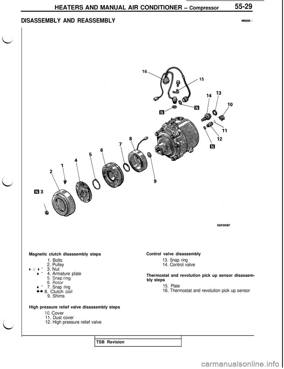
Magnetic clutch disassembly steps
1. Bolts
2. Pulley
l * l *3. Nutl *4. Armature plate
gI i;yirring
l *7. Snap ringF* 8. Clutch coil9. ShimsControl valve disassembly
13. Snap ring14. Control valveThermostat and revolution pick up sensor disassem-
bly steps
15. Plate16. Thermostat and revolution pick up sensorHigh pressure relief valve disassembly steps
10. Cover11. Dust cover
12. High pressure relief valveTSB Revision
Page 1112 of 1146
HEATERS AND MANUAL AIR CONDITIONER - Compressor
Spring
Valve
ompressor
2OPO286~
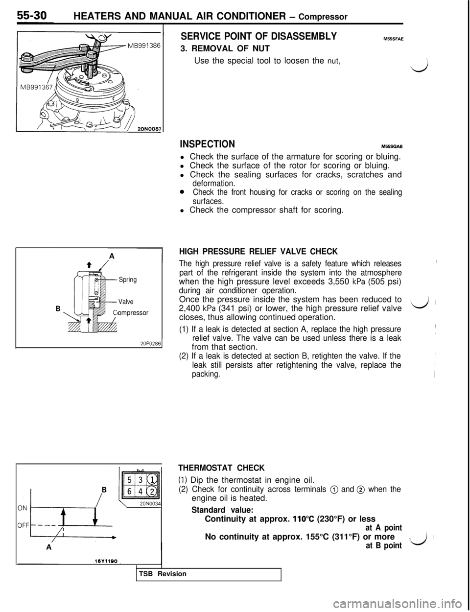
SERVICE POINT OF DISASSEMBLYMSlSFAE3. REMOVAL OF NUT
Use the special tool to loosen the nut,
INSPECTIONM55SGABl Check the surface of the armature for scoring or bluing.
l Check the surface of the rotor for scoring or bluing.
l Check the sealing surfaces for cracks, scratches and
deformation.
0Check the front housing for cracks or scoring on the sealing
surfaces.l Check the compressor shaft for scoring.
J
HIGH PRESSURE RELIEF VALVE CHECK
The high pressure relief valve is a safety feature which releasesI
part of the refrigerant inside the system into the atmospherewhen the high pressure level exceeds 3,550
kPa (505 psi)
during air conditioner operation.Once the pressure inside the system has been reduced to
2,400
kPa (341 psi) or lower, the high pressure relief valveL&Jcloses, thus allowing continued operation.
(1) If a leak is detected at section A, replace the high pressure
relief valve. The valve can be used unless there is a leak(from that section.
(2) If a leak is detected at section B, retighten the valve. If the
leak still persists after retightening the valve, replace the
packing.
THERMOSTAT CHECK
(1) Dip the thermostat in engine oil.
(2) Check for continuity across terminals @ and @ when theengine oil is heated.
Standard value:Continuity at approx.
110°C (230°F) or less
at A pointNo continuity at approx. 155°C (311°F) or more
,I
at B pointII;TSB Revision
Page 1113 of 1146
HEATERS AND MANUAL AIR CONDITIONER - Compressor55-3120N003d
2OFOO96
I
Ec-3
3180?+I! (25)zz
h34\
*
Engine speed rpm2OPO2S
\CrankshaftTapered part
20A0157
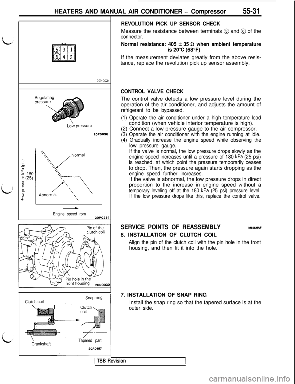
REVOLUTION PICK UP SENSOR CHECKMeasure the resistance between terminals
@ and @ of the
connector.
Normal resistance: 405 + 35 R when ambient temperatureis
20°C (68°F)
If the measurement deviates greatly from the above resis-
tance, replace the revolution pick up sensor assembly.
CONTROL VALVE CHECKThe control valve detects a low pressure level during the
operation of the air conditioner, and adjusts the amount of
refrigerant to be bypassed.
(1) Operate the air conditioner under a high temperature loadcondition (when vehicle interior temperature is high).
(2) Connect a low pressure gauge to the air compressor.
(3) Operate the air conditioner with the engine running at idle.
(4) Gradually increase the engine speed while observing the
low pressure gauge.
If the valve is normal, the low pressure drops slowly as the
engine speed increases until a pressure of 180
kPa (25 psi)
is reached, at which point the pressure temporarily ceasesto drop. Then, the pressure again starts dropping as the
engine speed further increases.If the valve is abnormal, the low pressure drops in direct
proportion to the increase in engine speed without a
temporary leveling off at the 180 kPa (25 psi) pressure level.
If the low pressure drops like this, replace the control valve.
SERVICE POINTS OF REASSEMBLYM556HAF
8. INSTALLATION OF CLUTCH COIL
Align the pin of the clutch coil with the pin hole in the fronthousing, and then fit it into the hole.
7. INSTALLATION OF SNAP RING
Install the snap ring so that the tapered surface is at the
outer side.
1 TSB Revision
Page 1114 of 1146
55-32HEATERS AND MANUAL AIR CONDITIONER - Comrxessor
no spline-
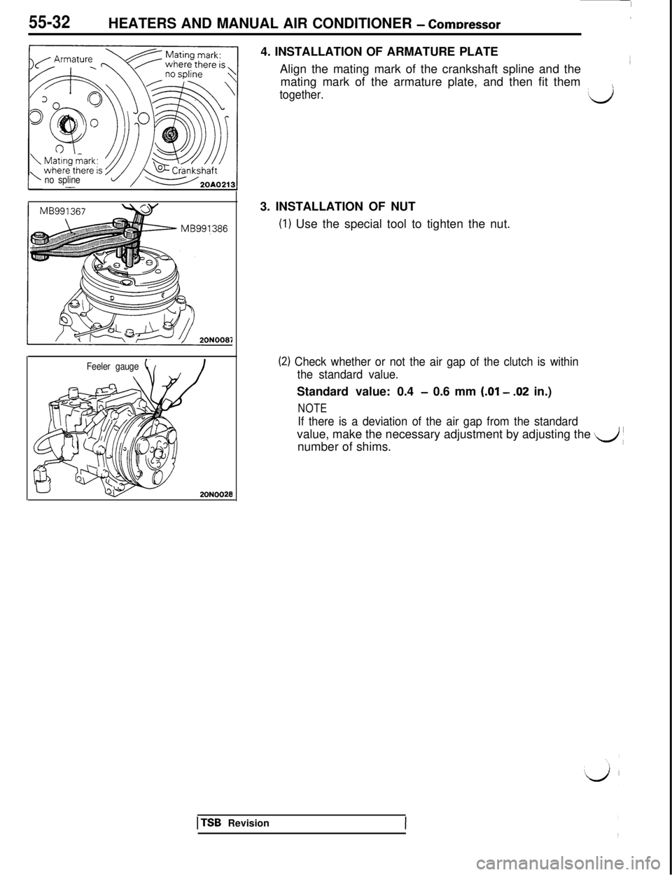
Feeler gauge4. INSTALLATION OF ARMATURE PLATE
Align the mating mark of the crankshaft spline and the
mating mark of the armature plate, and then fit them
together.‘%(J3. INSTALLATION OF NUT(I) Use the special tool to tighten the nut.
(2) Check whether or not the air gap of the clutch is within
the standard value.Standard value: 0.4
- 0.6 mm (.Ol - .02 in.)
NOTE
If there is a deviation of the air gap from the standardvalue, make the necessary adjustment by adjusting the
d 1number of shims.
1 TSB Revision
Page 1115 of 1146
HEATERS AND MANUAL AIR CONDITIONER - ::“dE:; and Condenser55-33
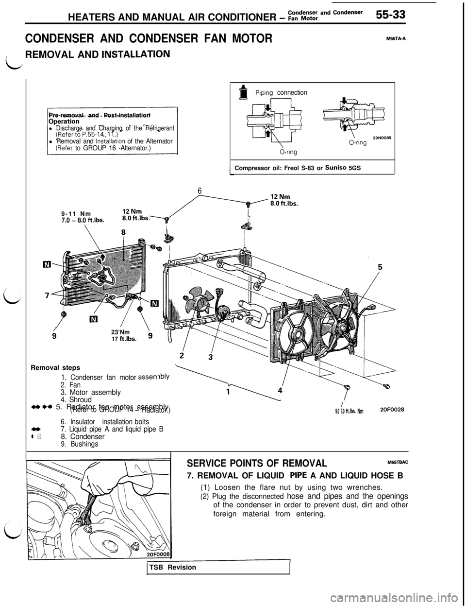
CONDENSER AND CONDENSER FAN MOTOR
MFSTA-A
idREMOVAL AND
IlilSTALLATlONPre-removal and Post-installation
l Discharge and Charging of the Refrigerant
l Removal and lnsiallation of the Alternator(Refey to GROUP 16 -Alternator.)
6
f: Piplng connection
@
20N00890-ring
d-ringCompressor oil: Freol S-83 or Suniso 5GS
9-11 Nm
7.0 - 8.0 ftlbs.
9’23’Nm17 ft.lbs.
asset-rRemoval steps1. Condenser fan motor
2. Fan
3. Motor assembly
4. Shroud
w w 5. Radiator fan motor assembly(Refer to GROUP 14- Radiator.)
Insulator installationbolts
6.4*7. Liquid pipe A and liquid pipe Bl *8. Condenser9.Bushings
/9.0 7.0ft.lbs. Nm2OFOO28
SERVICE POINTS OF REMOVALM!XTEtAC7. REMOVAL OF LIQUID
‘PIPE A AND LIQUID HOSE B
(1) Loosen the flare nut by using two wrenches.
(2) Plug the disconnected hose and pipes and the openingsof the condenser in order to prevent dust, dirt and other
foreign material from entering.
TSB Revision
Page 1116 of 1146
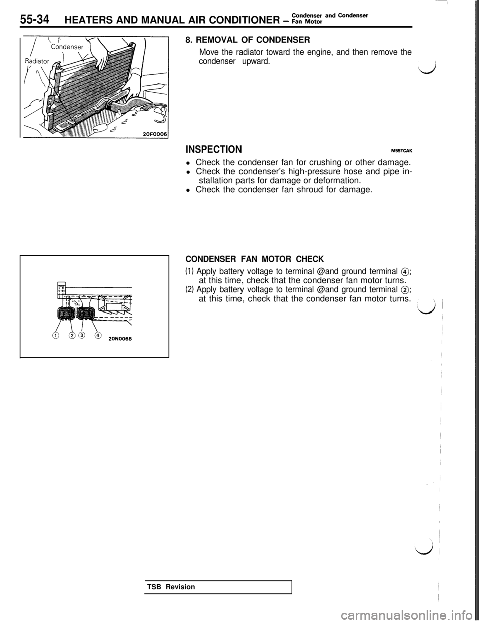
55-34HEATERS AND MANUAL AIR CONDITIONER - :t%%: and Condenser8. REMOVAL OF CONDENSER
Move the radiator toward the engine, and then remove the
condenser upward.
d
INSPECTIONM55TCAKl Check the condenser fan for crushing or other damage.
l Check the condenser’s high-pressure hose and pipe in-
stallation parts for damage or deformation.
l Check the condenser fan shroud for damage.
CONDENSER FAN MOTOR CHECK
(1) Apply battery voltage to terminal @and ground terminal 8;at this time, check that the condenser fan motor turns.
(2) Apply battery voltage to terminal @and ground terminal 0;at this time, check that the condenser fan motor turns.
TSB Revision
Page 1117 of 1146
HEATERS AND MANUAL AIR CONDITIONER - Rdrigerant Line55-35
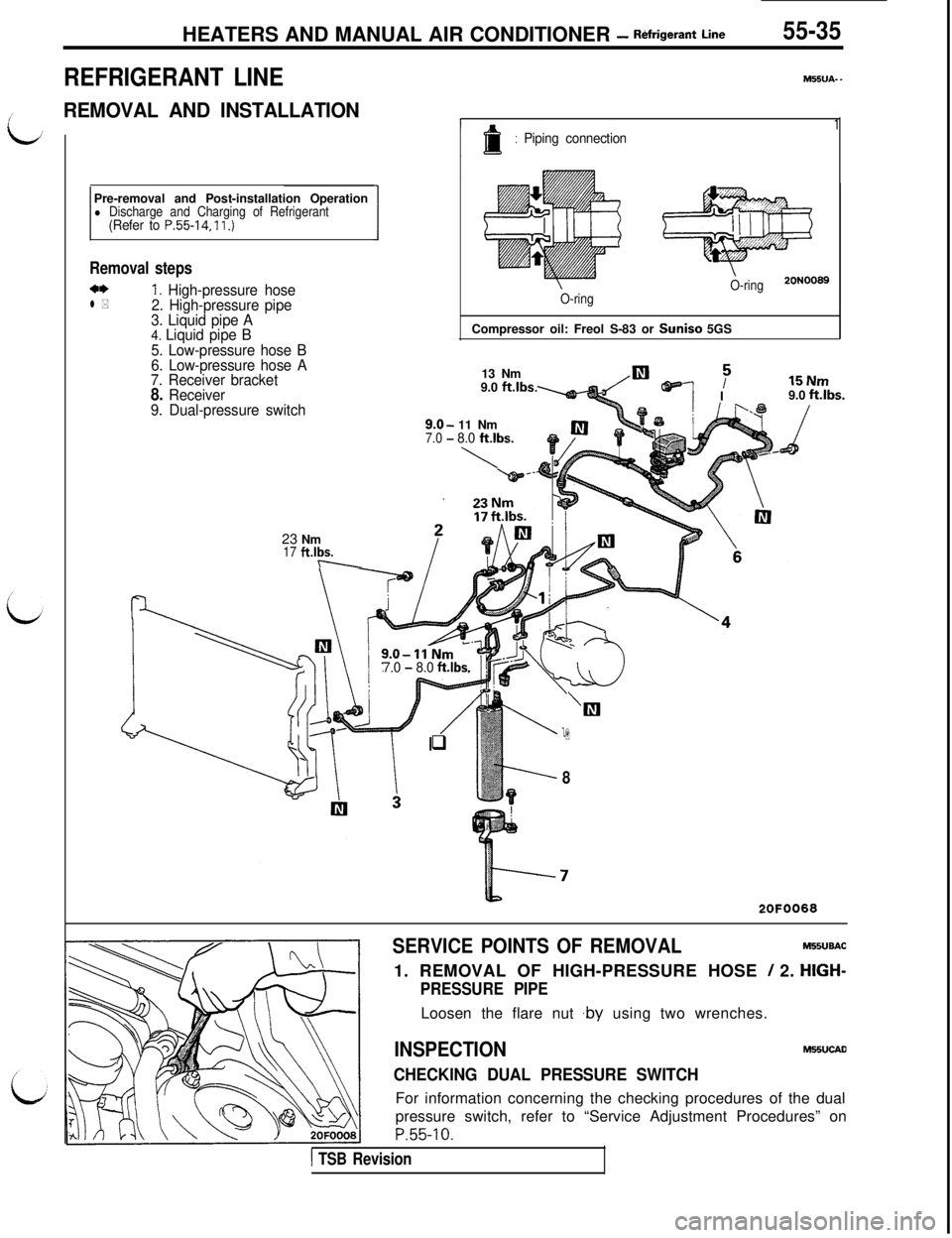
REFRIGERANT LINE
/’REMOVAL AND INSTALLATION
L;Pre-removal and Post-installation Operation
l Discharge and Charging of Refrigerant(Refer to P.55-14, 11.)
Removal steps
a*1. High-pressure hosel *2. High-pressure pipe
3. Liquid pipe A
4. Liquid pipe B
5. Low-pressure hose B
6. Low-pressure hose A
7. Receiver bracket
8. Receiver
9. Dual-pressure switch23 Nm
17 ft.lbs.-\-M55UA-
-
1: Piping connection
O-ring20N0089
1
O-ringCompressor oil: Freol S-83 or Suniso 5GS
13 Nm
9.0
ft.lbs.
9.0-11 Nm7.0 -8.0 ft.lbs.
\
TE NUTII” 1.1119.0 ft.lbs.
7.0 - 8.0 ft.lbs.
/
‘Ill
q9
8
2OFOO68
SERVICE POINTS OF REMOVALMIBUBAC
1. REMOVAL OF HIGH-PRESSURE HOSE
/ 2. HIGH-
PRESSURE PIPELoosen the flare nut ,by using two wrenches.
INSPECTIONMHUCAD
CHECKING DUAL PRESSURE SWITCHFor information concerning the checking procedures of the dual
pressure switch, refer to “Service Adjustment Procedures” on
P.55-10.
1 TSB Revision
Page 1118 of 1146
55-36 HEATERS AND MANUAL AIR CONDITIONER -Ventilators (Instrument Panel)
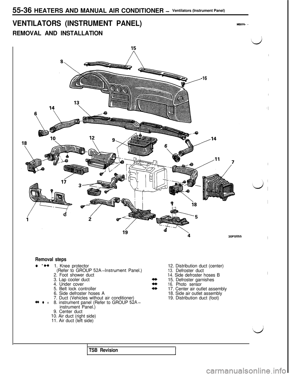
VENTILATORS (INSTRUMENT PANEL)M55YA- -
REMOVAL AND INSTALLATION
-16
/‘4
Removal steps
l * +a1. Knee protector
(Refer to GROUP 52A-Instrument Panel.)
2. Foot shower duct
3. Lap cooler duct
4. Under cover
5. Belt lock controller
6. Side defroster hoses A
7. Duct (Vehicles without air conditioner)
** l +8. instrument panel (Refer to GROUP 52A-instrument Panel.)
9. Center duct
10. Air duct (right side)
11. Air duct (left side)12. Distribution duct (center)
13.Defroster duct14. Side defroster hoses B
15. Defroster garnishes
16.Photo sensor17. Center air outlet assembly
18. Side air outlet assembly
19. Distribution duct (foot)2OFOO55
Ij
I
I
I
.I
I
I
!
I
‘d
TSB RevisionI
Page 1119 of 1146
HEATERS AND MANUAL AIR CONDITIONER -Ventilators (Instrument Panel) 55-37
/ 2OFOO321
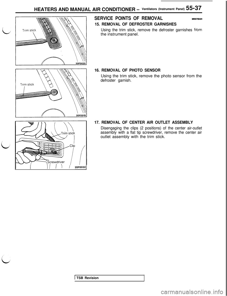
SERVICE POINTS OF REMOVALM55YBAH
15. REMOVAL OF DEFROSTER GARNISHES
Using the trim stick, remove the defroster garnishes fromthe instrument panel.
16. REMOVAL OF PHOTO SENSORUsing the trim stick, remove the photo sensor from the
defroster garnish.
17. REMOVAL OF CENTER AIR OUTLET ASSEMBLY
Disengaging the clips (2 positions) of the center air-outlet
assembly with a flat tip screwdriver, remove the center airoutlet assembly with the trim stick.
1 TSB Revision
Page 1120 of 1146
55-38Ventilators (Air Inlet
HEATERS AND MANUAL AIR CONDITIONER - and Air Outlet)
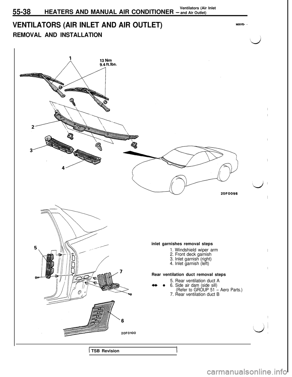
VENTILATORS (AIR INLET AND AIR OUTLET)M55YD. -
REMOVAL AND INSTALLATIONinlet garnishes removal steps
1. Windshield wiper arm
2. Front deck garnish
3. Inlet garnish (right)
4. Inlet garnish (left)Rear ventilation duct removal steps
5. Rear ventilation duct A** l6. Side air dam (side sill)
(Refer to GROUP 51 - Aero Parts.)7. Rear ventilation duct B
:LI’
I
I
I
I
‘d ’
I
I
I
1 TSB RevisionI