MITSUBISHI 3000GT 1991 Service Manual
Manufacturer: MITSUBISHI, Model Year: 1991, Model line: 3000GT, Model: MITSUBISHI 3000GT 1991Pages: 1146, PDF Size: 76.68 MB
Page 1121 of 1146
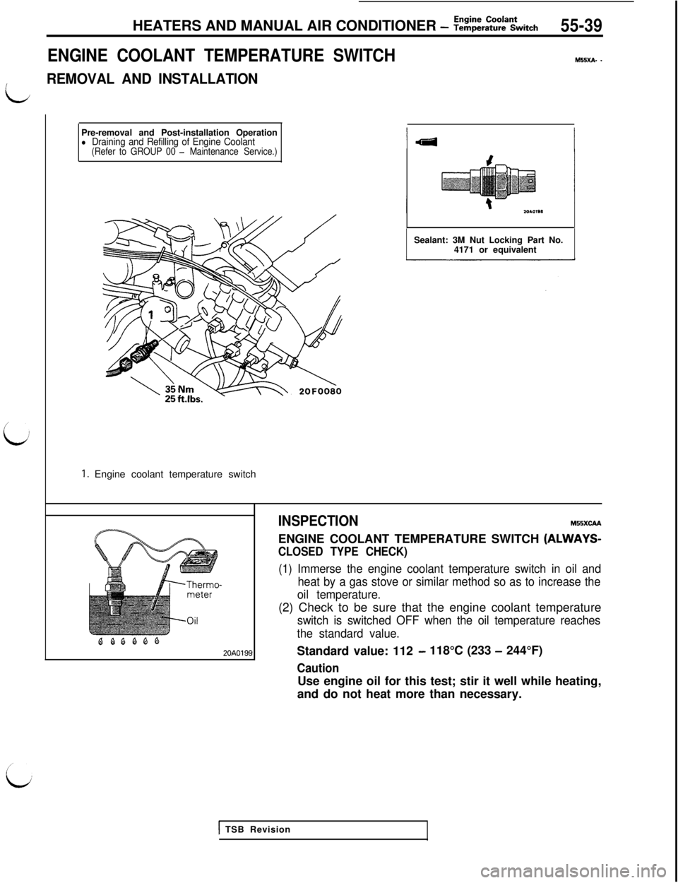
Pre-removal and Post-installation Operationl Draining and Refilling of Engine Coolant(Refer to GROUP 00 - Maintenance Service.)
1. Engine coolant temperature switchHEATERS AND MANUAL AIR CONDITIONER
- Z!&E%Ltch55-39
ENGINE COOLANT TEMPERATURE SWITCH
M55xA- -
L
REMOVAL AND INSTALLATIONSealant: 3M Nut Locking Part No.
4171 or equivalent
BQQQQQ20A0199INSPECTION
MSSXCAAENGINE COOLANT TEMPERATURE SWITCH
(ALWAYS-
CLOSED TYPE CHECK)
(1) Immerse the engine coolant temperature switch in oil and
heat by a gas stove or similar method so as to increase the
oil temperature.(2) Check to be sure that the engine coolant temperature
switch is switched OFF when the oil temperature reaches
the standard value.Standard value: 112
- 118°C (233 - 244°F)
CautionUse engine oil for this test; stir it well while heating,
and do not heat more than necessary.
1 TSB Revision
Page 1122 of 1146
55-40FULL AUTO AIR CONDITIONER - Troubleshooting
FULL AUTO AIR CONDITIONER
TROUBLESHOOTINGM55ECAF
TROUBLESHOOTING PROCEDUREd
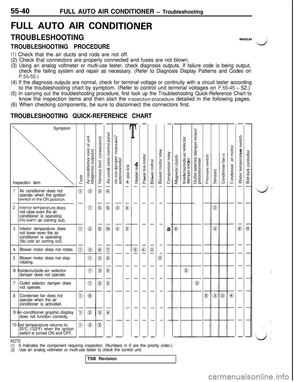
(1) Check that the air ducts and rods are not off.
(2) Check that connectors are properly connected and fuses are not blown.
(3) Using an analog voltmeter or multi-use tester, check diagnosis outputs. If failure code is being output,
check the failing system and repair as necessary. (Refer to Diagnosis Display Patterns and Codes on
P.55-55.)
(4) If the diagnosis outputs are normal, check for terminal voltage or continuity with a circuit tester accordingto the troubleshooting chart by symptom. (Refer to control unit terminal voltages on
P.55-45 - 52.)
(5) In carrying out the troubleshooting procedure, first look up the Troubleshooting Quick-Reference Chart toknow the inspection items and then start the
insoection orocedure detailed in the following pages.
(6) When checking components, be sure to disconnect the connectors first.
TROUBLESHOOTING QUICK-REFERENCE CHART
-
%I.?
0
-
(i;
0-
-
-
z
s
5
-
z3Ec-l-cm85LQgc .”0”SO0s“E$3
0
0
0
0.
0
0
0
-
-zbij2s”
-?‘-
aF&I
0
0
0
0
0
0
G
-
s
5
-
-
55n
>F8b5.-
F
8.$
0
:
G
0
G
is
z
-
G-
-
-
-
T4
L??ctE;
2-
-
-
G-
-
-
-
-
-
-.
-
b725
6
f53a0-
-
-
G-
-
-
-
-
-
-
86
E&3-0a-
-
-
-
3-
-
-
-
-
-
-
-
i?i?!
biiz?
E
0”-
-a
-
-
-
-
-
-
-
GE
21z6:1D-
-
-
-
-
0
-
-
-
-
-
;(if
zzit
5
5‘dTC
T-
-:
2
2
::ii3z;
2%;sjE1.0
;g5E
-
:
,,
,
1
-
-
-
-
0
-
-
-
-
-
k=eE00
t:0+i
-
-
a
-
-
-
-
-
-
-
-
b5E
5
&is*
s0-
-
-
-
-
-
-
G
-
-
-
-
5.T
Bz??3;i;b
Ecz
5-
-
0
-
-
-
-
-
-
-
-
1
225cn-
s
s----
s---
Symptom
Inspection item
7i;if
II:.?t.!
1E5z
iT-a,?z
5g< 13;$
zg
z
G-
-
-
-
-
-
-
.k?alL-0s
‘v, 0SE95anUE
ma‘0Y
s‘-5764
-
-
%G
-
-
-
-
-
-
-
Air conditioner does not
operate when the ignition
not raise even the air
conditioner is operating
(No’warm air coming out).
LJ
I
I~
‘L/,
3Interior temperature does
not lower even the air
conditioner is operating
(No cold air coming out).
4
Blower motor does not rotate.
5Blower motor does not stop
rotating.
06 Inside/outside-air selectordamper does not operate.
7Outlet selector damper does
not operate.
8Condenser fan does not
operate when the air
conditioner is activated.9 Air-conditioner graphic display
does not function correctly.
IO Set temperature returns to25°C (122°F) when the ignitionswitch is turned ON and OFF.
NOTE(1)
(2)0 indicates the component requiring inspection. (Numbers in 0 are the priority order.)
Use an analog voltmeter or multi-use tester to check the control unit.TSB Revision
Page 1123 of 1146
FULL AUTO AIR CONDITIONER - Troubleshootina55-41
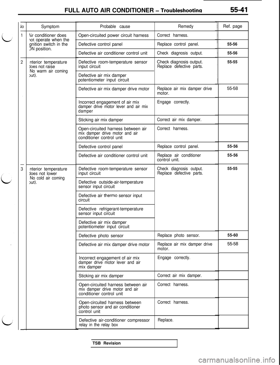
Symptom
4ir conditioner doeslot operate when the
gnition switch in the
3N position.
nterior temperature
lees not raiseNo warm air coming1ut).
nterior temperatureAoes not lowerNo cold air coming,ut).Probable cause
Open-circuited power circuit harness
Defective control panel
Defective air conditioner control unit
Defective room-temperature sensor
input circuit
Defective air mix damper
potentiometer input circuit
Remedy
Correct harness.
Replace control panel.
Check diagnosis output.
Check diagnosis output.Replace defective parts.
Defective air mix damper drive motorReplace air mix damper drivemotor.
Incorrect engagement of air mix
damper drive motor lever and air mix
damperEngage correctly.
Sticking air mix damper
Open-circuited harness between air
mix damper drive motor and airconditioner control unit
Defective control panel
Defective air conditioner control unit
Correct air mix damper.
Correct harness.
Replace control panel.
Replace air conditioner
control unit.
Defective room-temperature sensor
input circuit
Defective outside-air-temperature
sensor input circuit
Check diagnosis output.
Replace defective parts.
Defective air therm0 sensor input
circuit
Defective refrigerant-temperature
sensor input circuit
Defective air mix damper
potentiometer input circuit
Defective photo sensor
Replace photo sensor.
Defective air mix damper drive motorReplace air mix damper drive
motor.
Incorrect engagement of air mixdamper drive motor lever and airmix damper
Engage correctly.
Sticking air mix damper
Open-circuited harness between air
mix damper drive motor and airconditioner control unit
Open-circuited harness between
photo sensor and air conditioner
control unit
Correct air mix damper.
Correct harness.
Correct harness.
Defective air-conditioner compressorReplace.
relay in the relay boxTSB Revision
Ref. page
55-56
55-56
55-55
55-58
55-56
55-56
55-55
55-60
55-58
Page 1124 of 1146
55-42FULL AUTO AIR CONDITIONER - Troubleshooting
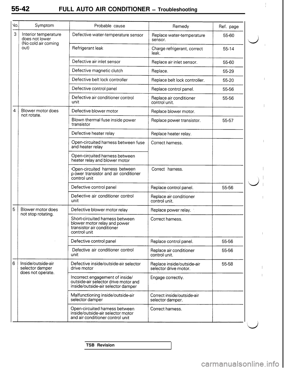
Open-circuitedharness between
ower transistor and air conditionerCorrect harness.
ective air conditioner control
Defective air conditioner controlTSB Revision
d,
I
I
I
I
LA1
I
I
I
Id
Page 1125 of 1146
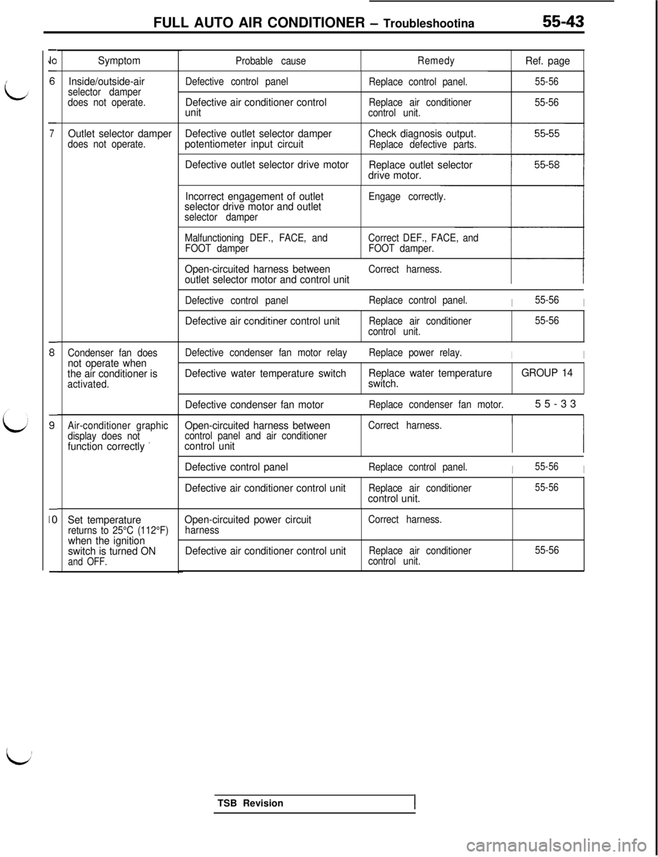
FULL AUTO AIR CONDITIONER - Troubleshootina55-43
-
JO
6
-
7
s
s
-
IO
-
Symptom
Inside/outside-air
selector damper
does not operate.
Outlet selector damperDefective outlet selector damperdoes not operate.potentiometer input circuit
Condenser fan doesnot operate when
the air conditioner is
activated.
Air-conditioner graphic
Open-circuited harness betweenCorrect harness.
display does notcontrol panel and air conditioner
function correctly ’control unitI I
Set temperaturereturns to 25°C (112°F)when the ignition
switch is turned ON
and OFF.
Probable causeRemedyRef. page
Defective control panel
Defective air conditioner control
unit
Replace control panel.
Replace air conditioner
control unit.55-56
55-56
Check diagnosis output.Replace defective parts.
Defective outlet selector drive motor
Replace outlet selector
drive motor.
Incorrect engagement of outlet
selector drive motor and outlet
selector damperEngage correctly.
Malfunctioning DEF., FACE, andCorrect DEF., FACE, and
FOOT damperFOOT damper.
Open-circuited harness betweenCorrect harness.outlet selector motor and control unit
Defective control panelReplace control panel.I55-56I
Defective air conditiner control unitReplace air conditioner
control unit.55-56
Defective condenser fan motor relayReplace power relay.
II
Defective water temperature switchReplace water temperature
switch.GROUP 14
Defective condenser fan motor
Replace condenser fan motor.55-33
Defective control panelReplace control panel.I55-56I
Defective air conditioner control unitReplace air conditionercontrol unit.
55-56
Open-circuited power circuitharnessCorrect harness.
Defective air conditioner control unitReplace air conditioner
control unit.55-56TSB Revision
I
Page 1126 of 1146
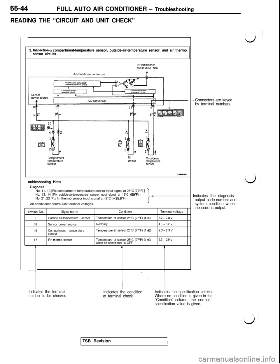
55-44FULL AUTO AIR CONDITIONER - Troubleshooting
READING THE “CIRCUIT AND UNIT CHECK”
3. hvqection Of compartment-temperature sensor, outside-air-temperature sensor, and air thermosensor circuits
Air condMnercompressor relay
Compartmenttemperat”re93”SCNFinX”SCH0utsrde.wtemperatureX”SOl
oubleshooting Hints
DlagnosrsNo. 11, 12 [Fix compartment temperature sensor input signal at 25°C (77”F).]
No. 13. 14 [Fix outside-air-temperature sensor input signal at 15°C (59”F).]No. 21, 22 [Fix fin therm0 sensor input signal at -2°C (-356”F).]Air conditioner control unit terminal voltagesI-
ermrnal No.Slgnal nameConditronTerrmnal voltage
5Outside-air-temperature sensorTemperature at sensor 25°C (77°F) (4 kf2)2.2-2.8V
10Sensor power sourceNormally4.8 - 5.2 V
16Compartment temperatureTkmperature at sensor 25°C (77°F) (4 k0)2.3-2.9vsensor
17Fin therm0 sensorTemperature at sensor 25°C (77°F) (4 k0)2.3 - 2.9 Vwhen alr conditioner is OFFA14
-
- Connectors are keyed
by terminal numbers.
Indicates the diagnosis
output code
nur6be.r and
system condition when
the code is output.
Indicates the terminal
number to be checked.Indicates the condition
at terminal check.Indicates the specification criteria.
Where no condition is given in the
“Condition” column, the normal
specification value is given.TSB Revision
1
Page 1127 of 1146
FULL AUTO AIR CONDITIONER - Troubleshooting
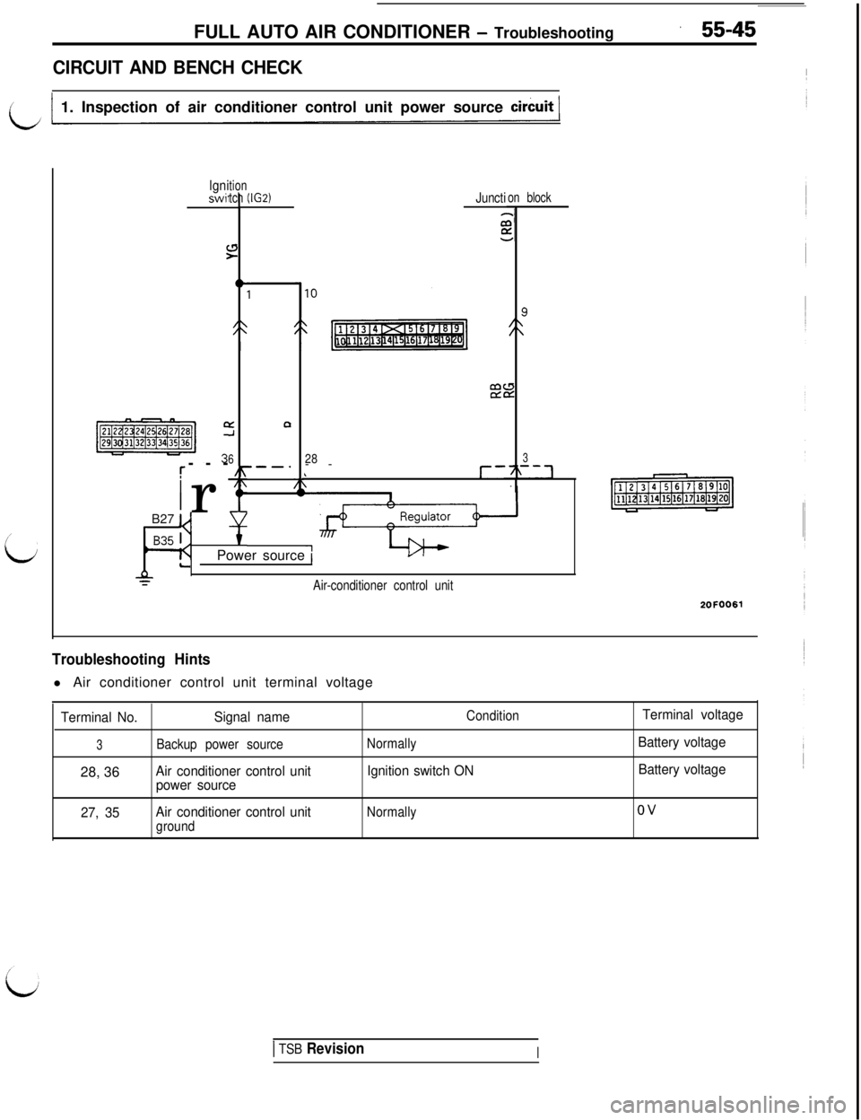
CIRCUIT AND BENCH CHECK
i1 1. Inspection of air conditioner control unit power source circuit 1
,
L
lgniswii
C:
I:Q
6r------.
i
17
Ir~ B27 u
tion
tch 1(IG2)Junction block2:
E
28--6\
3
r-7\--7
LPower source 1I I
AYAir-conditioner control unit
2OFOO61
Troubleshooting Hintsl Air conditioner control unit terminal voltage
Terminal No.Signal nameConditionTerminal voltage
3Backup power sourceNormallyBattery voltage28, 36
Air conditioner control unitIgnition switch ONBattery voltage
power source
27, 35Air conditioner control unit
Normallyov
ground
1 TSB RevisionI
Page 1128 of 1146
55-46FULL AUTO AIR CONDITIONER - Troubleshooting
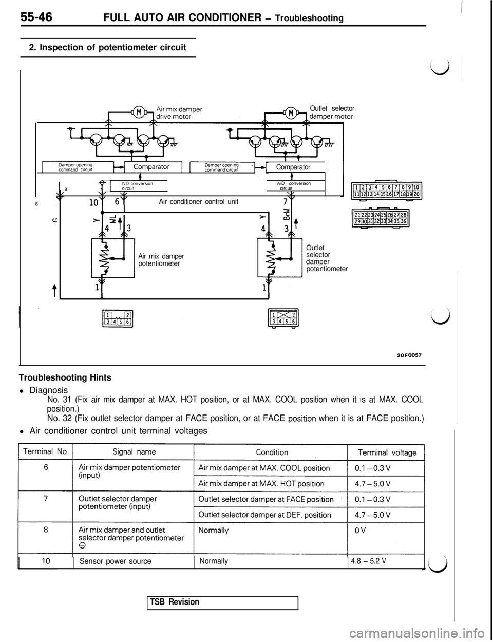
2. Inspection of potentiometer circuit
Outlet selector
command c~rcutl
i IComparator&8.
c!
t
Ia
Y[ND conversionA/D conversvmWC”l,CllCUll\/ \,1.y
lo” 6”Air conditioner control unit7‘”
94 72-2t4 3
~1
Air mix damper
potentiometer
z=-
4;t
e11I
Outlet
selector
damper
potentiometer
2OFOO57Troubleshooting Hints
l Diagnosis
No. 31 (Fix air mix damper at MAX. HOT position, or at MAX. COOL position when it is at MAX. COOL
position.)
No. 32 (Fix outlet selector damper at FACE position, or at FACE pgsition when it is at FACE position.)l Air conditioner control unit terminal voltages
Sensor power sourceNormally4.8 - 5.2 V
TSB Revision
Page 1129 of 1146
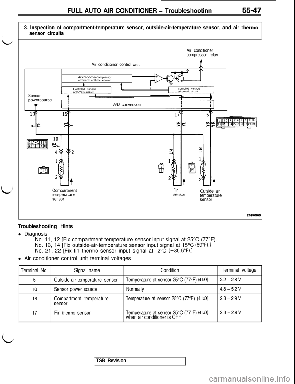
FULL AUTO AIR CONDITIONER - Troubleshootinn55-47
3. Inspection of compartment-temperature sensor, outside-air-temperature sensor, and air therm0
sensor circuits
Air conditioner
compressor relay
Air conditioner control
unitA~rconditlonercompiessor
command arllhmew ctrcutc#
Sensorpowersource
Controlled variableIControlled variable
-IIIA/D conversion
Compartment
temperaruresensor
Finsensor
?J
Outside air
temperature
sensor2OFOO60
Troubleshooting Hintsl Diagnosis
No. 11, 12 [Fix compartment temperature sensor input signal at 25°C (77°F).
No. 13, 14 [Fix outside-air-temperature sensor input signal at 15°C
(59”Fj.INo. 21, 22 [Fix fin
therm0 sensor input signal at -2°C (-35.6”FJ.ll Air conditioner control unit terminal voltages
Terminal No.Signal nameConditionTerminal voltage
5Outside-air-temperature sensorTemperature at sensor 25°C (77°F) (4 klR)2.2 - 2.8 V
10Sensor power sourceNormally4.8 - 5.2 V
16Compartment temperatureTemperature at sensor 25°C (77°F) (4 klR)2.3 - 2.9 V
sensor
17Fin therm0 sensorTemperature at sensor 25°C (77°F) (4 k0)2.3 - 2.9 Vwhen air conditioner is OFF
TSB Revision
Page 1130 of 1146
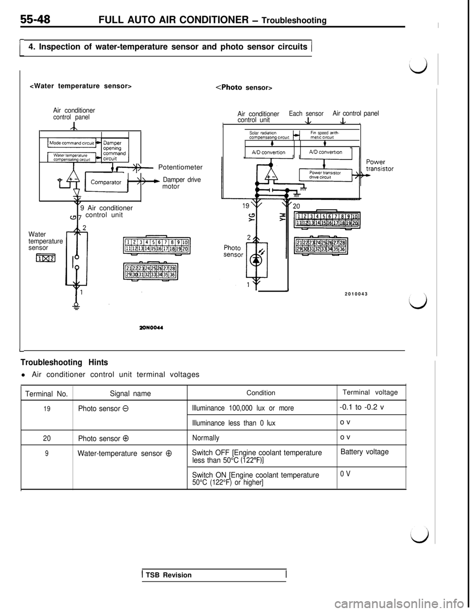
55-48FULL AUTO AIR CONDITIONER - Troubleshooting
[4. Inspection of water-temperature sensor and photo sensor circuits (
Air conditionercontrol panel
A
{ f*)- Potentiometer
‘>/b Damper drive
motor
\/\,9 Air conditioner
a 7 control unit
Water
temperature
sensor
m
Air conditionerEach sensorcontrol unit&
Air control panel
I.L .Solar radmtmnFin speed arlth-compensating ClrC”itmetIC ClrCUlt#t
A/D convertionND convemon
J2010043
I-
Troubleshooting Hintsl Air conditioner control unit terminal voltages
Terminal No.Signal nameConditionTerminal voltage
19Photo sensor 0llluminance 100,000 lux or more-0.1 to -0.2 v
llluminance less than 0 Iuxov
20Photo sensor 0Normallyov
9Water-temperature sensor 0Switch OFF [Engine coolant temperature
less than 50°C (122”F)]
Battery voltage
Switch ON [Engine coolant temperature
0 V
50°C (122°F) or higher]
1 TSB Revision