MITSUBISHI 3000GT 1991 Service Manual
Manufacturer: MITSUBISHI, Model Year: 1991, Model line: 3000GT, Model: MITSUBISHI 3000GT 1991Pages: 1146, PDF Size: 76.68 MB
Page 1131 of 1146
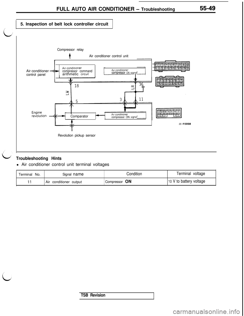
FULL AUTO AIR CONDITIONER - Troubleshooting55-495. Inspection of belt lock controller circuit
Compressor relay
tAir conditioner control unitAir conditioner
+control panelAir
condltloner,c.compressor commandAH condmonerarithmetic
circuitcompressor ONstgnal
ComparatorAir condltlonercompressor ON signal20 FOO58
Revolution pickup sensor
LiTroubleshooting Hintsl Air conditioner control unit terminal voltages
Terminal No.
Signal nameConditionTerminal voltage
11Air conditioner outputCompressor ONIO V to battery voltage
TSB Revision
Page 1132 of 1146
55-50FULL AUTO AIR CONDITIONER - Troubleshooting
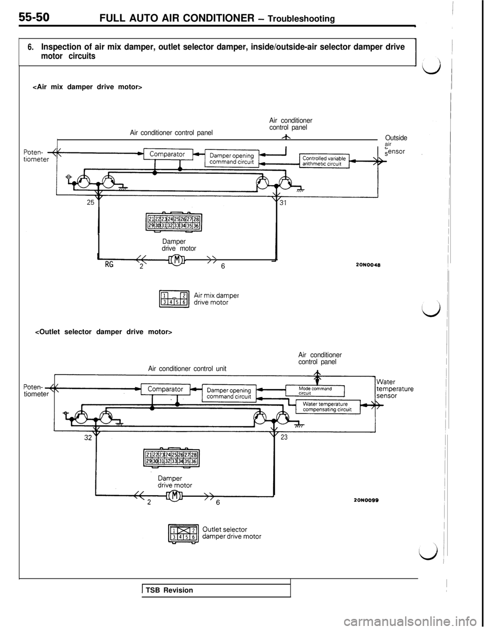
6.Inspection of air mix damper, outlet selector damper, inside/outside-air selector damper drive
motor circuits
Air conditioner
Air conditioner control panelcontrol panel
/hOutsideair
f:nsor
Damper
drive motor
\\
” 6
Air conditioner control unit
Poten-tiomet
20N0048
Air conditioner
control panel
23
20N0099
1 TSB Revision
Page 1133 of 1146
FULL AUTO AIR CONDITIONER - Troubleshooting55-51
L
iv
i
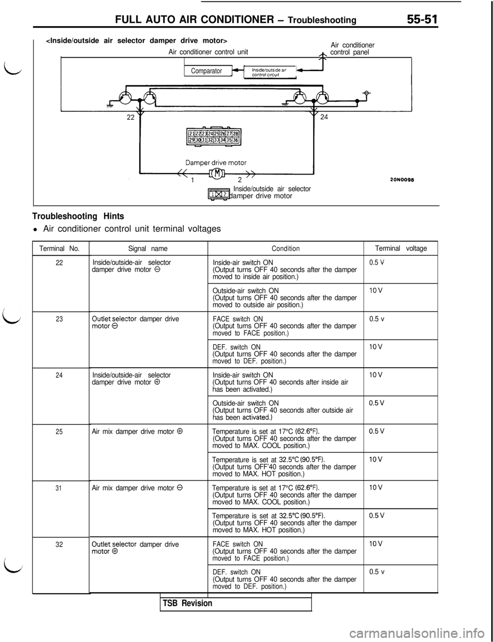
Air conditioner
Air conditioner control unith control panel
ComparatorInsideloutslde atrcontrol ClrCUlt
Ezz3
Inside/outside air selector12 damper drive motor
Troubleshooting Hintsl Air conditioner control unit terminal voltages
Terminal No.
22
23
24
25
31
32
20NO098
Signal name
Inside/outside-air selector
damper drive motor
0
ConditionTerminal voltage
Inside-air switch ON
0.5 v(Output turns OFF 40 seconds after the damper
moved to inside air position.)
Outside-air switch ON
1ov(Output turns OFF 40 seconds after the damper
moved to outside air position.)$ot~kt~lector
damper driveFACE switch ON0.5 v
(Output turns OFF 40 seconds after the damper
moved to FACE position.)
DEF. switch ON
1ov(Output turns OFF 40 seconds after the dampermoved to DEF. position.)
Inside/outside-air selector
damper drive motor 0Inside-air switch ON
(Output turns OFF 40 seconds after inside air
has been activated.)IOV
Outside-air switch ON0.5v(Output turns OFF 40 seconds after outside air
has been activated.)
Air mix damper drive motor 0Temperature is set at 17°C (62.6”F).0.5v(Output turns OFF 40 seconds after the damper
moved to MAX. COOL position.)
Temperature is set at
32.5”C (90.5”F).1ov(Output turns OFF’40 seconds after the damper
moved to MAX. HOT position.)
Air mix damper drive motor
0Temperature is set at 17°C (62.6”F).IOV(Output turns OFF 40 seconds after the damper
moved to MAX. COOL position.)
Temperature is set at
32.5”C (90.5”F).0.5v(Output turns OFF 40 seconds after the damper
moved to MAX. HOT position.)
PO;:; Elector damper driveFACE switch ONIOV(Output turns OFF 40 seconds after the dampermoved to FACE position.)
DEF. switch ON
0.5 v
(Output turns OFF 40 seconds after the damper
moved to DEF. position.)
TSB Revision
Page 1134 of 1146
55-52FULL AUTO AIR CONDITIONER - Troubleshooting
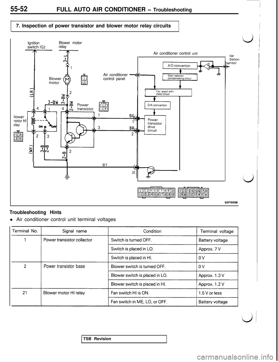
7. Inspection of power transistor and blower motor relay circuitsllower
Potor t?lay
El12
3 4
Ignitionswitch IG2Blower motor
relay
Air conditioner
-control panel
IWY/\2’
a.T
Air conditioner control unit
Fan speed anth-mete circw
)lardiatlon‘nsor2OFOO59
Troubleshooting Hintsl Air conditioner control unit terminal voltages
Power transistor baseTSB Revision
Page 1135 of 1146
FULL AUTO AIR CONDITIONER - Troubleshootina55-53r
---.__------
2OFOO8:
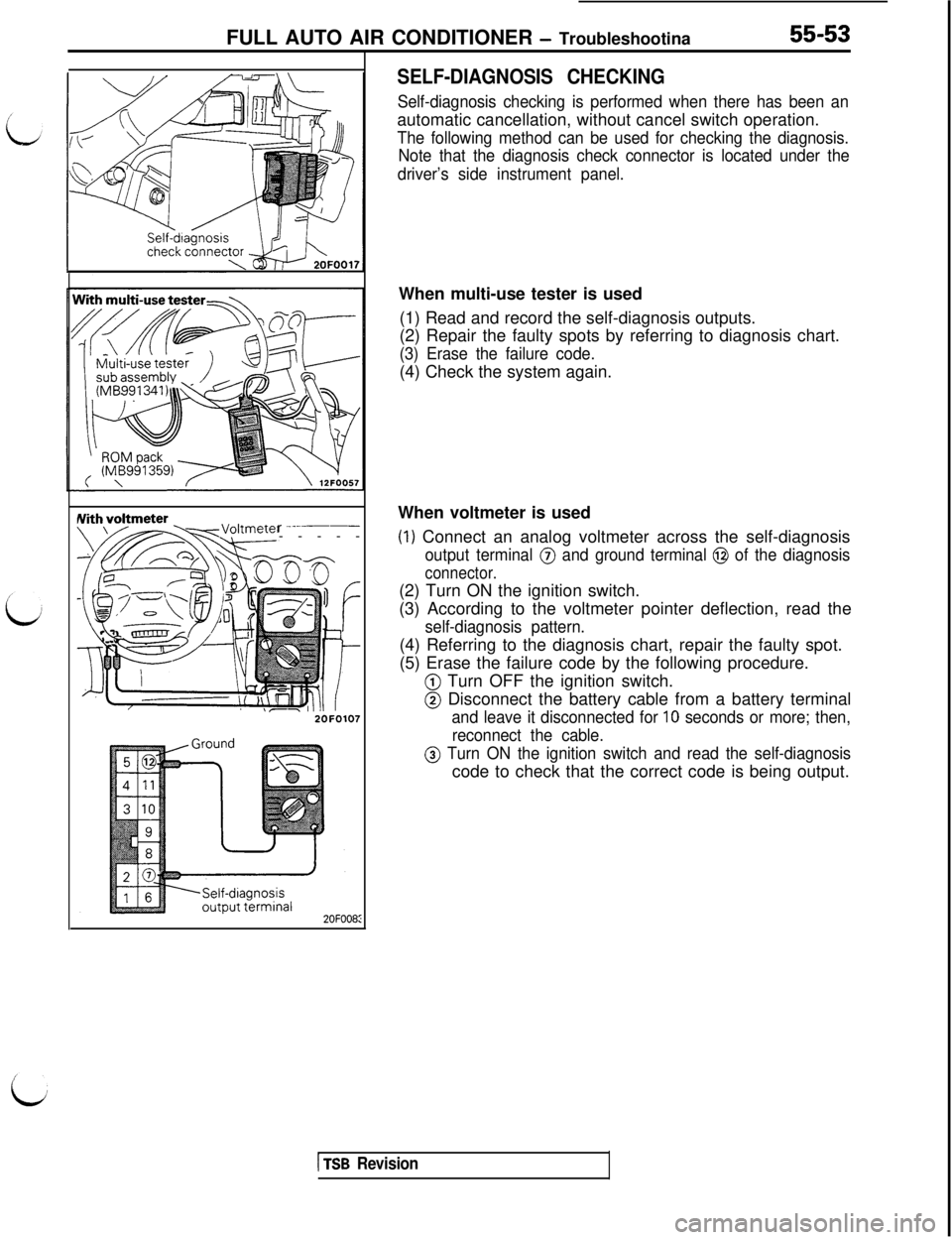
SELF-DIAGNOSIS CHECKING
Self-diagnosis checking is performed when there has been anautomatic cancellation, without cancel switch operation.
The following method can be used for checking the diagnosis.
Note that the diagnosis check connector is located under the
driver’s side instrument panel.When multi-use tester is used
(1) Read and record the self-diagnosis outputs.
(2) Repair the faulty spots by referring to diagnosis chart.
(3) Erase the failure code.(4) Check the system again.
When voltmeter is used
(1) Connect an analog voltmeter across the self-diagnosis
output terminal @ and ground terminal @ of the diagnosis
connector.(2) Turn ON the ignition switch.
(3) According to the voltmeter pointer deflection, read the
self-diagnosis pattern.(4) Referring to the diagnosis chart, repair the faulty spot.
(5) Erase the failure code by the following procedure.
@ Turn OFF the ignition switch.
@ Disconnect the battery cable from a battery terminal
and leave it disconnected for 10 seconds or more; then,
reconnect the cable.
@ Turn ON the ignition switch and read the self-diagnosiscode to check that the correct code is being output.
1 TSB Revision
Page 1136 of 1146
SERVICE DATA
ternno.Inspection
point
MethodCriteria
Probable cause
Normal
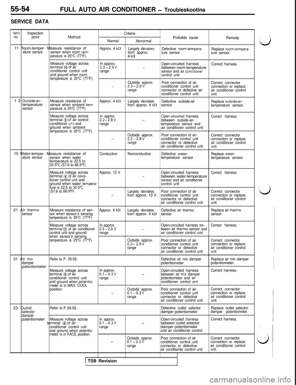
AbnormalRemedy11 Room-temper- Measure resistance of
sensor when room tem- ature sensorperature is 25°C (77°F).
Approx. 4 kS1Largely devrates
from approx.Defective room-tempera-
Replace room-tempera-
ture sensor
ture sensor.4
kll
Measure voltage across
In approx.
terminal @I of airOpen-circuited harness
Correct harness.2.3-2.9v-conditioner control unitbetween room-temperaturerange
sensor and air condrtionerand ground when room
control unittemperature is 25°C (77°F).Outside approx.
Poor connection of air
Correct connector-2.3-2.9vconditioner control unit
connection or replace’rangeconnector or defective air
air conditioner control
conditioner control unitunit.13
Outside-air-
Measure resistance of
Approx. 4 kllLargely deviates
Defective outside-air
Replace outside-air-temperaturesensor when ambient tem-
from approx. 4 kf2sensor
temperature sensor.
sensorperature is 25°C (77°F).
Measure voltage acrossIn approx.terminal @of air controlOpen-crrcuited harnessCorrect harness.2.2-2.8V-between outside-air-
conditioner unrt and
range
temperature sensor and
ground when ambient
air conditioner control unit
temperature is 25°C (77°F).Outside approx.Poor connection of air-
Correct connector-2.2-2.8Vconditioner control unit
connection or replacerangeconnector or defectiveair conditioner control
air conditioner control unitunit.15 Water-temper- Measure resistance of
ConductiveNonconductiveDefective water-
Replace water-
ature sensor
sensor when watertemperature sensor
temperature sensor.
temperature is 22.5 to
30.5”C (57.6 to 86.9”F).21 Air therm0
sensorMeasure voltage acrossApprox. 12 V
Open-circuited harness
Correct harness.terminal @ of air condi--between water-temperaturetioner control unit and
sensor and air conditioner
ground when water tempera-
control unit
ture is 22.5 to 30.5”C(57.6 to 86.9”F).Largely deviatesPoor connection of airCorrect connector-from approx. 12 Vconditioner control unitconnection or replace
connector or defectiveair conditioner control
air conditioner control unitunit.
Measure resistance of
sen-Approx. 4 kS2Largely deviatesDefective air therm0Replace air therm0
sor when sensor’s sensing
from approx. 4 kb2sensorsensor.temperature is 25°C (77°F).
Measure voltage acrossIn approx.Open-circuited harness be-Correct harness.termrnal 0 of air conditioner2.3 - 2.9 V-tween air therm0 sensor and
control unit and groundrangeair conditioner control unit
when sensor’s sensing
temperature is 25°C (77°F).Outside approx.
Poor connection of airCorrect connector2.3-2.9vconditioner control unitconnection or replace
rangeconnector or defectiveair conditioner control
air conditioner control unit
unit.31 Air
mrx
Refer to P. 55-59.Defective air mix damperReplace air mix damper
damperpotentiometerpotentiometer.
potentiometer
-Measure voltage acrossIn approx.
Open-circuited harnessCorrect harness.
terminal @of airO.l-0.3v-between air mrx damper
conditioner control unitrangepotentiometer and arrand ground when potentio-conditioner control unrtmeter is in MAX. COOL
position.Outside approx.Poor connection of airCorrect connector
-0.1 -0.3vconditioner control unitconnection or replace
rangeconnector or defectiveair conditioner control
air conditioner control unitunit.33 Outlet
Refer to P. 55-59.Defective outlet selectorReplace outlet selector
selectordamper potentiometerdamper potentiometer.
damperpotentiometer
Measure voltage acrossIn approx.Open-circuited harnessCorrect harness.terminal @of air0.1 -0.3v-between outlet selectorconditioner control unitrangedamper potentiometerand ground when potentio-and air conditioner control
meter is in FACE position._Outside approx.Poor connection of airCorrect connector-0.1 -0.3vconditioner control unitconnection or replace
rangeconnector or defectiveair conditioner control
air conditioner control unit
unit.FULL AUTO AIR CONDITIONER
- Troubleskootina
1 TSB Revision
Page 1137 of 1146
FULL AUTO AIR CONDITIONER - Troubleshootina55-55
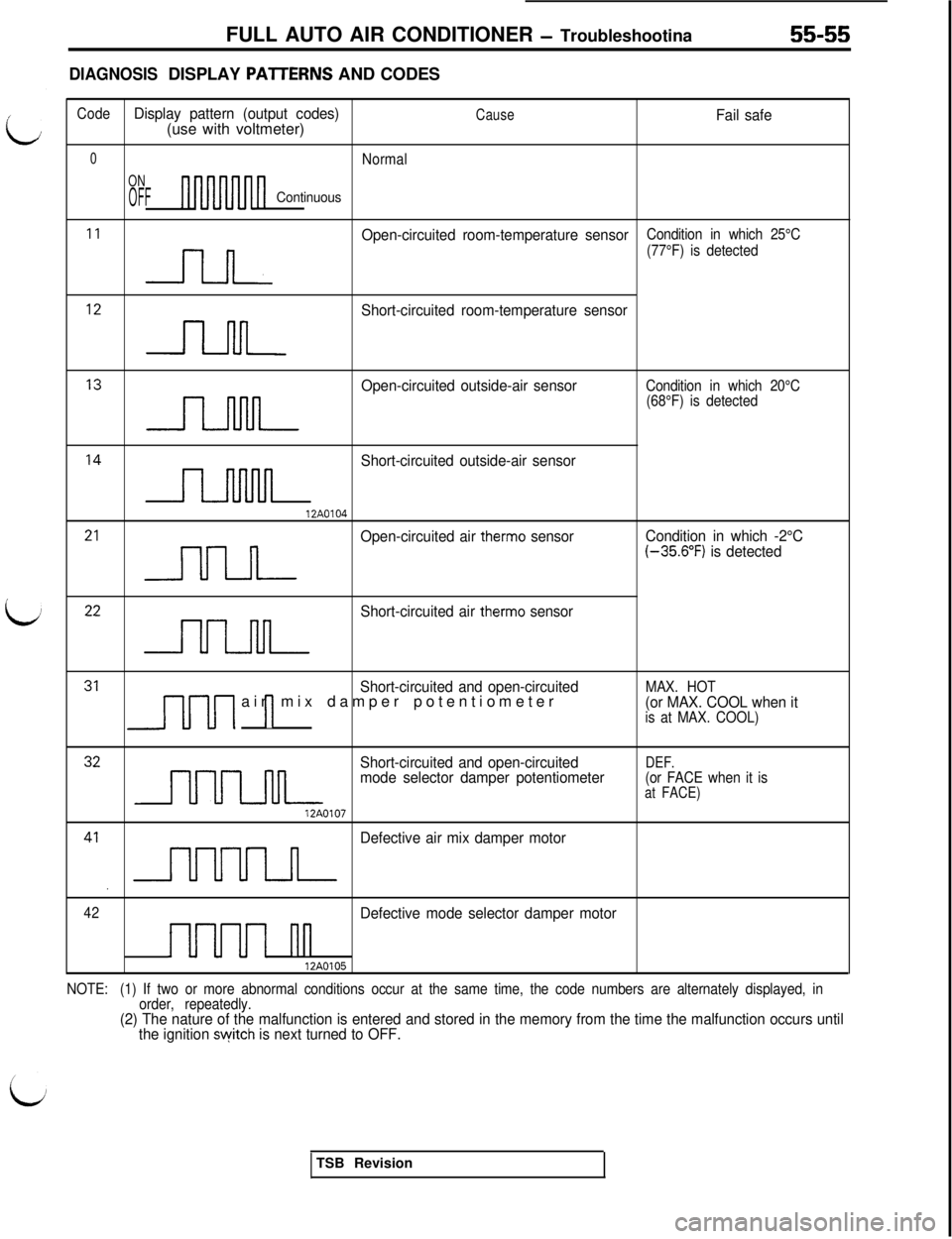
DIAGNOSISDISPLAY PAlTERNS AND CODES
/
L
ii
CodeDisplay pattern (output codes)CauseFail safe(use with voltmeter)
0Normal
ON
OFFContinuous
I1 n
Open-circuited room-temperature sensorCondition in which 25°C
(77°F) is detected
I2 n
Short-circuited room-temperature sensor
I3 n
Open-circuited outside-air sensorCondition in which 20°C
(68°F) is detected
I4 n
Short-circuited outside-air sensor
12A0104
21 -,llJlL
Open-circuited air therm0 sensorCondition in which -2°C(-35.6”F) is detected
22 nn
Short-circuited air therm0 sensor
31 J-[-u1 1Short-circuited and open-circuitedair mix damper potentiometerMAX. HOT(or MAX. COOL when itis at MAX. COOL)
32 nnn
Short-circuited and open-circuitedDEF.mode selector damper potentiometer(or FACE when it isat FACE)
12A0107
41, nnnn
Defective air mix damper motor
42Defective mode selector damper motor
1uuuI nn12A0105
NOTE:(1) If two or more abnormal conditions occur at the same time, the code numbers are alternately displayed, in
order, repeatedly.
(2) The nature of the malfunction is entered and stored in the memory from the time the malfunction occurs until
the ignition switch is next turned to OFF.TSB Revision
Page 1138 of 1146
55-56FULL AUTO AIR CONDITIONERSafety Precautions I Service Adjustment Procedures I- Air Conditioner Control Panel, Air Condiiioner Control Unit
SAFETY PRECAUTIONSSame as those given in HEATERS AND MANUAL AIR CONDITIONER. (Refer to
P.55-9.)
SERVICE ADJUSTMENT PROCEDURESSame as those given in HEATERS AND MANUAL AIR CONDITIONER. (Refer to
P.55-10.)
M55FEAVI
AIR CONDITIONER CONTROL PANEL, AIR CONDITIONER CONTROL
UNIT
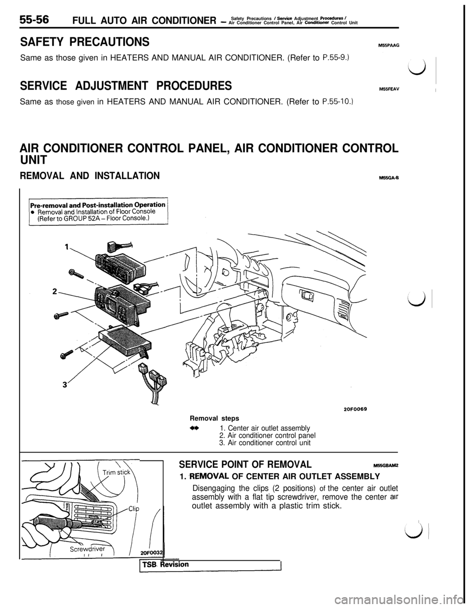
REMOVAL AND INSTALLATIONhl!XGA-E
2OFOO69Removal steps
*I)1. Center air outlet assembly
2. Air conditioner control panel
3. Air conditioner control unit
SERVICE POINT OF REMOVALMWSGBAMZ1.
.REMOVAL OF CENTER AIR OUTLET ASSEMBLY
Disengaging the clips (2 positions) of the center air outlet
assembly with a flat tip screwdriver, remove the center
airoutlet assembly with a plastic trim stick.
I
ij!
Page 1139 of 1146
FULL AUTO AIR CONDITIONER -Power Transistor, Belt Lock Controller55-57
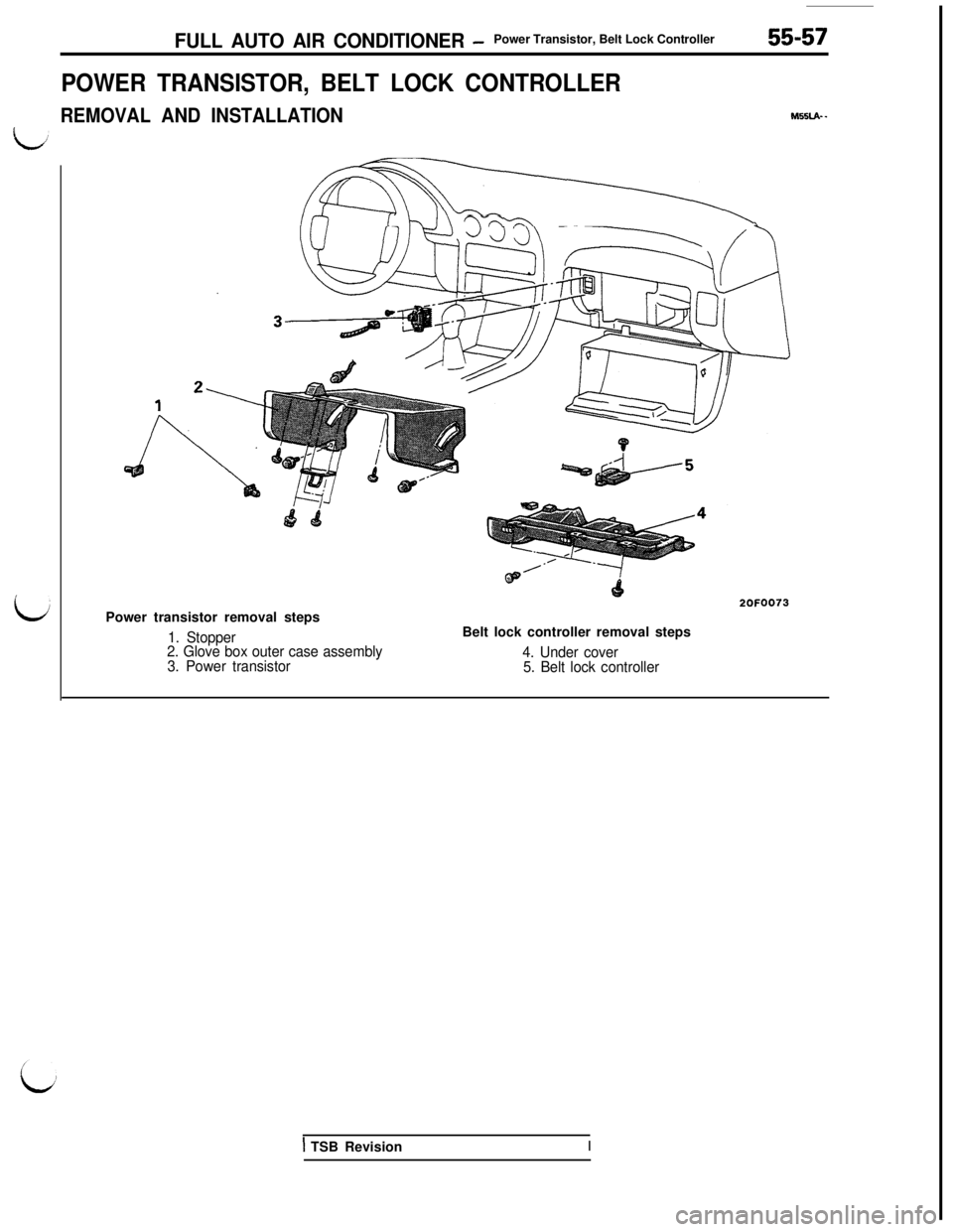
POWER TRANSISTOR, BELT LOCK CONTROLLER
REMOVAL AND INSTALLATION
J?nPower transistor removal steps
1. Stopper
2. Glove box outer case assembly
3. Power transistor
2OFOO73Belt lock controller removal steps
M55LA- -
4. Under cover
5. Belt lock controller
1 TSB RevisionI
Page 1140 of 1146
55-58FULL AUTO AIR CONDITIONER - Damper Control Motor As=W
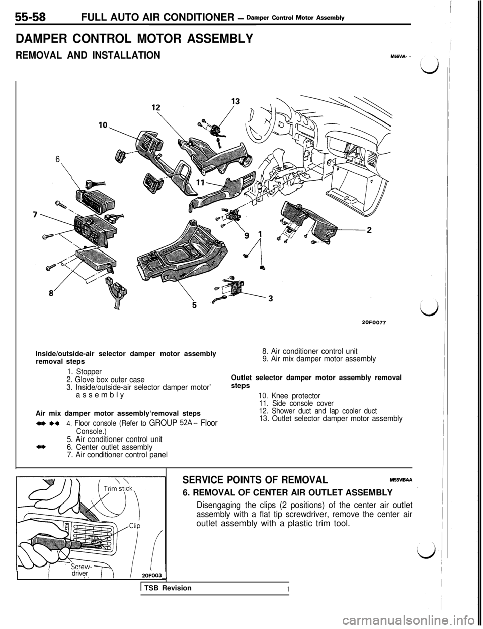
DAMPER CONTROL MOTOR ASSEMBLY
REMOVAL AND INSTALLATIONM55VA- -
6
\
2OFOO77Inside/outside-air selector damper motor assembly
removal steps
8. Air conditioner control unit
9. Air mix damper motor assembly
1. Stopper
2. Glove box outer case
3. Inside/outside-air selector damper motor’assemblyOutlet selector damper motor assembly removal
steps
IO. Knee protector11. Side console coverAir mix damper motor assembly‘removal steps
w *a4. Floor console (Refer to GROUP 52A- Floor
Console.)5. Air conditioner control unita*6. Center outlet assembly
7. Air conditioner control panel
12. Shower duct and lap cooler duct13. Outlet selector damper motor assembly
IIdriver, ,/ 20;003--t
1 TSB Revision
SERVICE POINTS OF REMOVALM55vaAA6. REMOVAL OF CENTER AIR OUTLET ASSEMBLY
Disengaging the clips (2 positions) of the center air outlet
assembly with a flat tip screwdriver, remove the center airoutlet assembly with a plastic trim tool.
1