torque MITSUBISHI 3000GT 1991 Owner's Manual
[x] Cancel search | Manufacturer: MITSUBISHI, Model Year: 1991, Model line: 3000GT, Model: MITSUBISHI 3000GT 1991Pages: 1146, PDF Size: 76.68 MB
Page 246 of 1146
13-140FUEL SYSTEM - On-vehicle Inspection of MPI Components
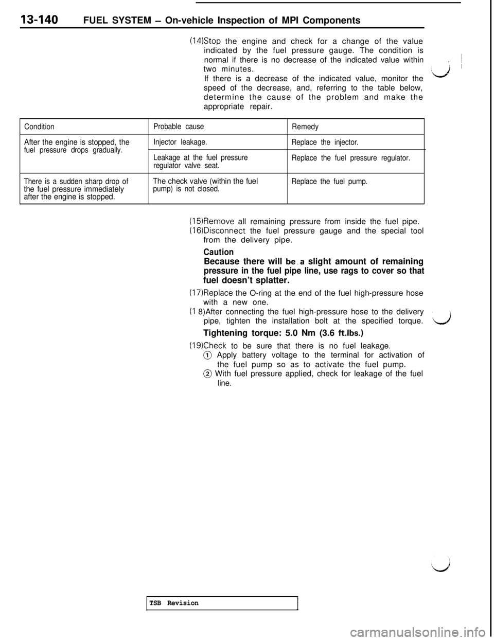
(14)Stop the engine and check for a change of the value
indicated by the fuel pressure gauge. The condition is
normal if there is no decrease of the indicated value within~
two minutes.
,If there is a decrease of the indicated value, monitor the
:d ’speed of the decrease, and, referring to the table below,
determine the cause of the problem and make the
appropriate repair.
Condition
After the engine is stopped, thefuel pressure drops gradually.Probable cause
Injector leakage.
Leakage at the fuel pressure
regulator valve seat.Remedy
Replace the injector.
Replace the fuel pressure regulator.
There is a sudden sharp drop of
the fuel pressure immediately
after the engine is stopped.The check valve (within the fuelpump) is not closed.Replace the fuel pump.
(15)Remove all remaining pressure from inside the fuel pipe.(16)Disconnect the fuel pressure gauge and the special tool
from the delivery pipe.
CautionBecause there will be.a slight amount of remaining
pressure in the fuel pipe line, use rags to cover so thatfuel doesn’t splatter.
(17)Replace the O-ring at the end of the fuel high-pressure hose
with a new one.(I 8)After connecting the fuel high-pressure hose to the delivery
pipe, tighten the installation bolt at the specified torque.
dTightening torque: 5.0 Nm (3.6 ftlbs.)
(19)Check to be sure that there is no fuel leakage.@ Apply battery voltage to the terminal for activation of
the fuel pump so as to activate the fuel pump.@ With fuel pressure applied, check for leakage of the fuel
line.
TSB Revision
Page 254 of 1146
13-148FUEL SYSTEM - Fuel Tank
Canistide
Do3041Flare nut
Se&e side
0310430%
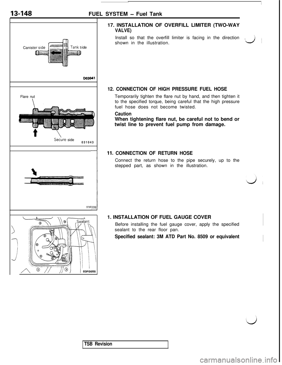
e:00817. INSTALLATION OF OVERFILL LIMITER (TWO-WAY
VALVE)Install so that the overfill limiter is facing in the direction
’,~
shown in the illustration.L.&l
12. CONNECTION OF HIGH PRESSURE FUEL HOSETemporarily tighten the flare nut by hand, and then tighten it
to the specified torque, being careful that the high pressure
fuel hose does not become twisted.
CautionWhen tightening flare nut, be careful not to bend or
twist line to prevent fuel pump from damage.
11. CONNECTION OF RETURN HOSEConnect the return hose to the pipe securely, up to the
stepped part, as shown in the illustration.
1. INSTALLATION OF FUEL GAUGE COVER
Before installing the fuel gauge cover, apply the specified
sealant to the rear floor pan.
Specified sealant: 3M ATD Part No. 8509 or equivalent
TSB Revision
Page 256 of 1146
13-150FUEL SYSTEMFuel Pump and Fuel Gauge Unit Assembly- and Overfill Limiter (Two-Way Valve)
Rubber hose
9Flare nut
Secure side
03Yo43Camst
ide
DO304INSPECTION
MlBUCAB
OVERFILL LIMITER (TWO-WAY VALVE)~
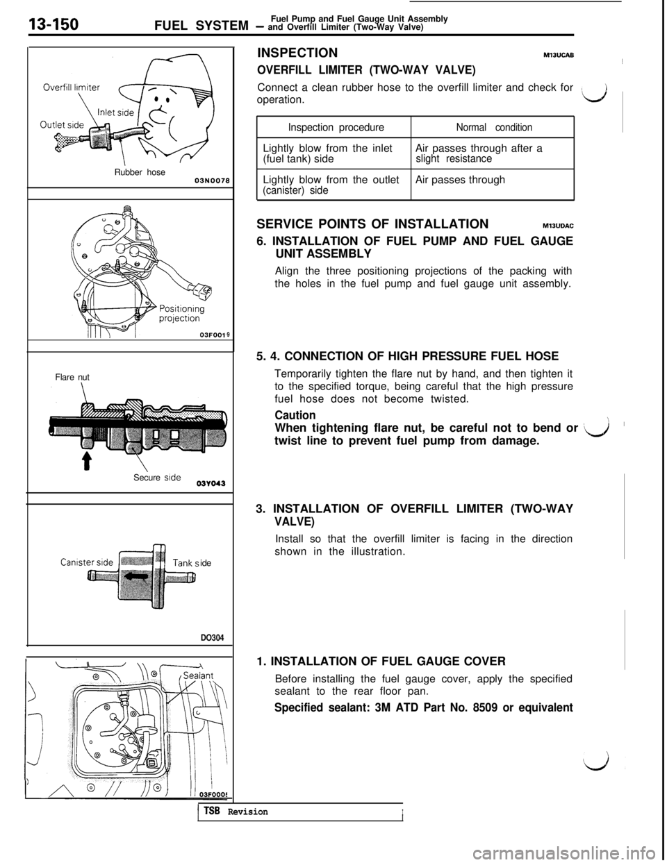
Connect a clean rubber hose to the overfill limiter and check for
operation.
‘d
Inspection procedureNormal conditionLightly blow from the inlet
(fuel tank) sideAir passes through after a
slight resistanceLightly blow from the outlet
(canister) sideAir passes through
SERVICE POINTS OF INSTALLATION
M13UDAC6. INSTALLATION OF FUEL PUMP AND FUEL GAUGE
UNIT ASSEMBLY
Align the three positioning projections of the packing with
the holes in the fuel pump and fuel gauge unit assembly.
5. 4. CONNECTION OF HIGH PRESSURE FUEL HOSE
Temporarily tighten the flare nut by hand, and then tighten it
to the specified torque, being careful that the high pressure
fuel hose does not become twisted.
CautionWhen tightening flare nut, be careful not to bend or
[J’twist line to prevent fuel pump from damage.\3. INSTALLATION OF OVERFILL LIMITER (TWO-WAY
VALVE)Install so that the overfill limiter is facing in the direction
shown in the illustration.
1. INSTALLATION OF FUEL GAUGE COVER
Before installing the fuel gauge cover, apply the specified
sealant to the rear floor pan.
Specified sealant: 3M ATD Part No. 8509 or equivalent
1 TSB RevisionIII
Page 258 of 1146
13-152FUEL SYSTEM- Fuel Line and Vapor Line
03FOO3
05FOO735 Nm7r; ft
Ihr-k” ._..I_.
@dFlare nut,xSERVICE POINTS OF REMOVAL
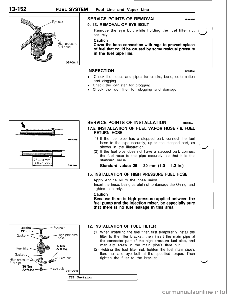
MlBKBAQ9. 13. REMOVAL OF EYE BOLT
Remove the eye bolt while holding the fuel filter nut
\securely.
Caution
Cover the hose connection with rags to prevent splash
of fuel that could be caused by some residual pressurein the fuel pipe line.
INSPECTION
MIBKCAJ
lCheck the hoses and pipes for cracks, bend, deformation
and clogging.
l Check the canister for clogging.
l Check the fuel filter for clogging and damage.
SERVICE POINTS OF INSTALLATION
MlSKDAU17.5. INSTALLATION OF FUEL VAPOR HOSE
/ 8. FUEL
RETURN HOSE
(1) If the fuel pipe has a stepped part, connect the fuel
hose to the pipe securely, up to the stepped part, as
shown in the illustration.
Iti(2) If the fuel pipe does not have a stepped part, connect
the fuel hose to the pipe securely, so that it is the
standard value.
Standard value: 25
- 30 mm (1.0 - 1.2 in.)
15. INSTALLATION OF HIGH PRESSURE FUEL HOSEApply engine oil to the hose union.
Insert the hose, being careful not to damage the O-ring, and
tighten securely.
CautionBecause there is high pressure applied between the
fuel pump and the injection mixer, be especially sure
that there is no fuel leakage in this area.
12. INSTALLATION OF FUEL FILTER(1) When installing the fuel filter, first temporarily install the
filter to the filter bracket; then insert the main pipe at
the connector part of the high pressure fuel pipe, and
manually screw in the main pipe’s flare nut.
(2) Holding the fuel filter nut, tighten the fuel main pipe’s
flare nut and eye bolt at the specified torque. Then
tighten the filter to the bracket.
TSB Revision1
‘d
Page 259 of 1146
FUEL SYSTEM - Fuel Filter13453
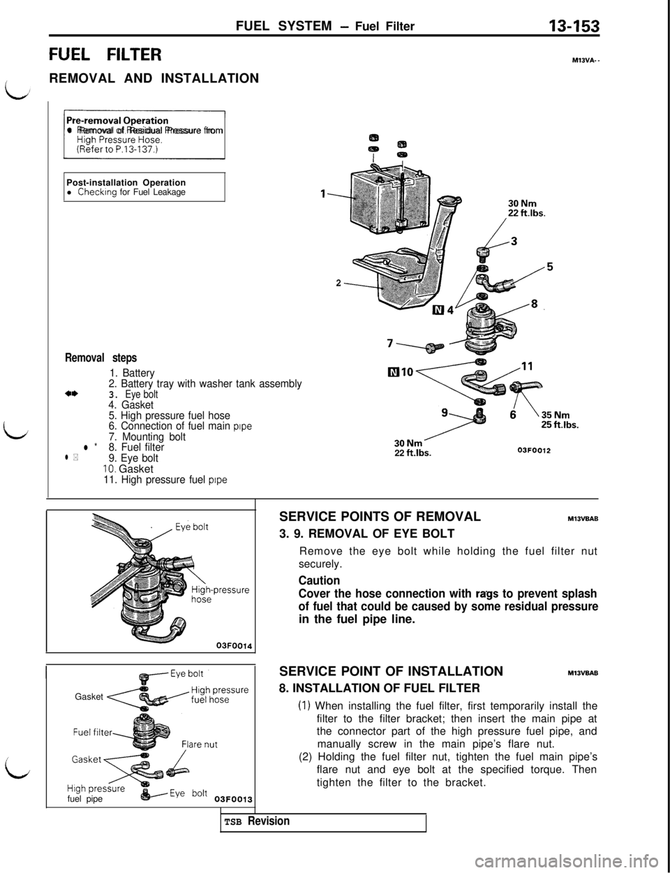
FUEL FILTERM13VA-.
/REMOVAL AND INSTALLATION
i&J
L
/Il Removal of Residual Pressure from
Post-installation Operation
l Checking for Fuel Leakage
Removal steps
1. Battery
2. Battery tray with washer tank assembly
3. Eye bolt4. Gasket
5. High pressure fuel hose
6. Connection of fuel main
pipe7. Mounting boltl *8. Fuel filterl *9. Eye bolt10. Gasket11. High pressure fuel pipe
l---
222 ft.lbs.03FOO12
Gasket
fuel pipe
&----Eye bo’t 03FOO13SERVICE POINTS OF REMOVAL
MlSVBAB3. 9. REMOVAL OF EYE BOLT
Remove the eye bolt while holding the fuel filter nut
securely.
Caution
Cover the hose connection with
rags to prevent splash
of fuel that could be caused by some residual pressurein the fuel pipe line.
SERVICE POINT OF INSTALLATION
M13VBAB8. INSTALLATION OF FUEL FILTER
(1) When installing the fuel filter, first temporarily install the
filter to the filter bracket; then insert the main pipe at
the connector part of the high pressure fuel pipe, and
manually screw in the main pipe’s flare nut.
(2) Holding the fuel filter nut, tighten the fuel main pipe’s
flare nut and eye bolt at the specified torque. Then
tighten the filter to the bracket.
TSB Revision
Page 260 of 1146
13-154FUEL SYSTEM - Detonation Sensor
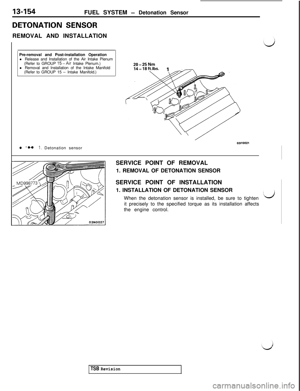
DETONATION SENSORREMOVAL AND INSTALLATION
Pre-removal and Post-installation Operation
l Release and Installation of the Air Intake Plenum
(Refer to GROUP
15-Air Intake Plenum.)
l Removal and Installation of the Intake Manifold
(Refer to GROUP 15
- Intake Manifold.)
l * +*I. Detonation sensor
20-25NmSERVICE POINT OF REMOVAL
1. REMOVAL OF DETONATION SENSOR
SERVICE POINT OF INSTALLATION
1. INSTALLATION OF DETONATION SENSOR
When the detonation sensor is installed, be sure to tighten
Idit precisely to the specified torque as its installation affects
the engine control.
TSB Revision
Page 297 of 1146
COOLING - Specifications / Troubleshooting
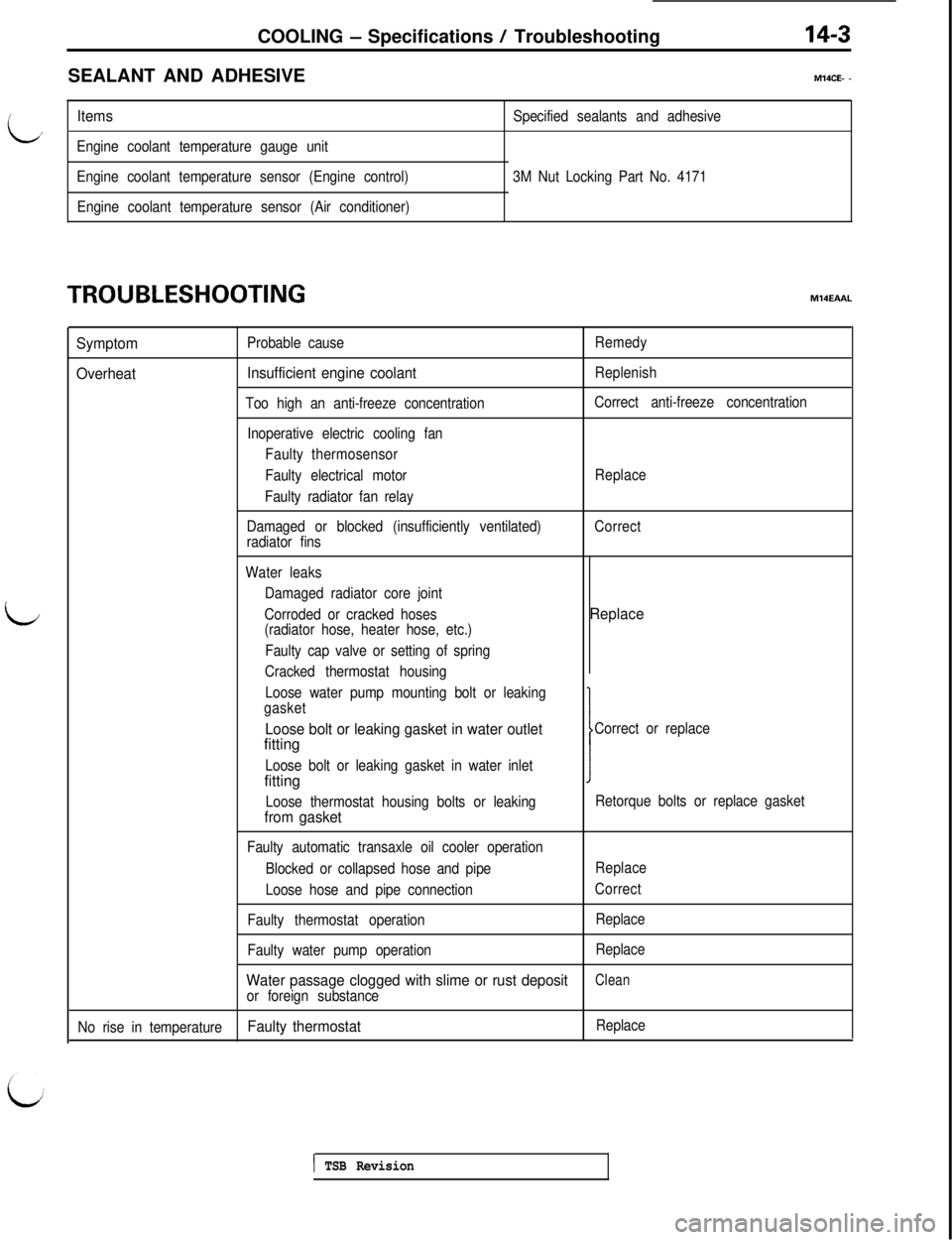
SEALANT AND ADHESIVE14-3
MMCE- -
/
id
ItemsSpecified sealants and adhesive/
Engine coolant temperature gauge unit
Engine coolant temperature sensor (Engine control)
Engine coolant temperature sensor (Air conditioner)3M Nut Locking Part No. 4171
TROUBLESHOOTING
L
MllEAAL
Symptom
OverheatProbable cause
Insufficient engine coolant
Too high an anti-freeze concentration
Inoperative electric cooling fan
Faulty thermosensor
Faulty electrical motor
Faulty radiator fan relayRemedy
Replenish
Correct anti-freeze concentration
Replace
Damaged or blocked (insufficiently ventilated)
radiator finsCorrect
Water leaks
Damaged radiator core joint
Corroded or cracked hoses
(radiator hose, heater hose, etc.)
Faulty cap valve or setting of spring
Cracked thermostat housing
Loose water pump mounting bolt or leaking
gasket
Replace
Loose bolt or leaking gasket in water outlet
I
Correct or replacefitting
Loose bolt or leaking gasket in water inletfitting
Loose thermostat housing bolts or leakingfrom gasket
Retorque bolts or replace gasket
Faulty automatic transaxle oil cooler operation
Blocked or collapsed hose and pipeReplace
Loose hose and pipe connectionCorrect
Faulty thermostat operationReplace
Faulty water pump operationReplace
Water passage clogged with slime or rust depositClean
or foreign substance
No rise in temperature
Faulty thermostatReplace
( TSB Revision
Page 338 of 1146

15-28INTAKE AND EXHAUST - Exhaust Manifold
EXHAUST MANIFOLD
REMOVAL AND INSTALLATION
MlINA-C
12-15Nm9 - 11 ft.lbs.
Pre-removal and Post-installation Operationl Removal and Installation of Turbocharger Assembly(Refer to P.15-18, 21.)Removal steps of exhaust manifold (front)
I. Heat protector** 2. Exhaust manifold (front)** 3. Exhaust manifold stay4. GasketRemoval steps of exhaust manifold (rear)
5. Heat protector*+ 6. Exhaust manifold (rear)7. Gasket05FOO25
v
Cone disc spring
7lNOll5TSB Revision
INSPECTIONMl5NCAU3
Check the following points; replace the part if a problem is
found.
l Check for damage of cracking of any part.
SERVICE POINTS OF INSTALLATIONMlBNDAH
6. INSTALLATION OF EXHAUST MANIFOLD (REAR)
Tighten the nuts in the following order.
(1) Tighten five nuts @ to 30 Nm (22 ft.lbs.1.(2) Tighten nuts
@I to 47 - 53 Nm (34 - 38 ft.lbs.1.(3) Back off nuts @ until torque value of 10 Nm
(7 ft.lbs.1 is
achieved.
(4) Tighten nuts
@I to 29 - 31 Nm (21 - 22 ft.lbs.1.
NOTE
1.Fit the cone disc spring with the grooved side facing
the nut.
2. Install the nut, cone disc spring and washer in the
order shown in the illustration.
iJ
I
‘d
Page 339 of 1146

INTAKE AND EXHAUST - Exhaust Manifold
Exhaust
manifold
stay
Exhaustmanifold
05FOO17
Cone disc spring71NOll;3. INSTALLATION OF EXHAUST MANIFOLD STAY
With the exhaust manifold stay resting on the exhaust
manifold, fit it along with the exhaust manifold over the
studs.
2.
INSTALLATION OF EXHAUST MANIFOLD (FRONT)
Tighten the nuts in the following order.
(1) Tighten four nuts @ to 30 Nm (22 ft.lbs.1.(2) Temporarily tighten the turbocharger to the exhaust
manifold.
(3) Tighten nut @ to 30 Nm (22
ft.lbs.1.(4) Tighten nuts @ and @ to 47
- 53 Nm (34 - 38 ft.lbs.).
(5) Back off nuts @ and @ until torque value of
10 Nm (7
ftlbs.) is achieved.
(6) Tighten nuts @ and @ to 29
- 31 Nm (21 - 22 ft.lbs.1.NOTE
1.Fit the cone disc spring with the grooved side,facing
the nut.
2. Install the nut, cone disc spring and washer in the
order shown in the illustration.
TSB Revision
Page 349 of 1146

EMISSION CONTROL - Crankcase Emission Control System17-5
CRANKCASE EMISSION CONTROL SYSTEM
COMPONENTS LOCATIONJ
Ir--‘-l7FU1002
Name
Positive crankcase ventilation valveSymbolA
i{
ventilation valve\”
------rLYJ7EM0134M17KA--
CRANKCASE VENTILATION SYSTEM INSPEC-
TIONM171ABG(1) After disconnecting the ventilation hose from the positive
crankcase ventilation valve, disconnect the positive crank-
case ventilation valve from the rocker cover, and reconnect
the positive crankcase ventilation valve to the ventilation
hose.
(2) Idle engine, put finger on the opening end of the positive
crankcase ventilation valve, and check that the negative
pressure of the intake manifold is felt with finger.
NOTEAt this time, the plunger in the positive crankcase ventila-
tion valve moves back and forth.
(3) If negative pressure is not felt, clean or replace the positive
crankcase ventilation valve.
POSITIVE CRANKCASE VENTILATION VALVEMl7lACC
INSPECTION
(1) Remove the positive crankcase ventilation valve.
(2) Insert a thin stick into the positive crankcase ventilation
valve from the threaded side to check that the plunger
moves.
(3) If the plunger does not move, the positive crankcase
ventilation valve is clogged. Clean it or replace.
INSTALLATIONInstall the positive crankcase ventilation valve and tighten to
specified torque.
Specified tightening torque:
10 Nm (7.2 ft.lbs.1TSB Revision