MITSUBISHI 3000GT 1991 Service Manual
Manufacturer: MITSUBISHI, Model Year: 1991, Model line: 3000GT, Model: MITSUBISHI 3000GT 1991Pages: 1146, PDF Size: 76.68 MB
Page 581 of 1146
FRONT AXLE - Troubleshooting / Service Adjustment Procedures
TROUBLESHOOTING
26-5
MPBEBAA
i.
Symptom
Vehicle pulls to one
side
Vibration
Shimmy
Excessive noiseProbable cause
Seizure of drive shaft ball joint
Abnormal wear, play or seizure of wheel bearing
Malfunction of front suspension or steering
Bend, damage or abnormal wear of drive shaft
Play in drive shaft and hub serration
Abnormal wear, play or seizure of wheel bearing
Improper wheel alignment
Malfunction of front suspension or steering
Broken boot, grease leakage
Bend, damage or abnormal wear of drive shaft
Play of drive shaft and hub serration
Abnormal wear, play or seizure of center bearing
Abnormal wear, play or seizure of wheel bearing
Loose wheel nut
Malfunction of front suspension and steering
Remedy
Replace
Replace
Adjust or replace
Replace
Replace
Replace
Adjust or replace
Adjust or replace
Replace, repack grease
Replace
Replace
Replace
Replace
Retighten
Adjust or replace
u11 A0285
SERVICE ADJUSTMENT PROCEDURES
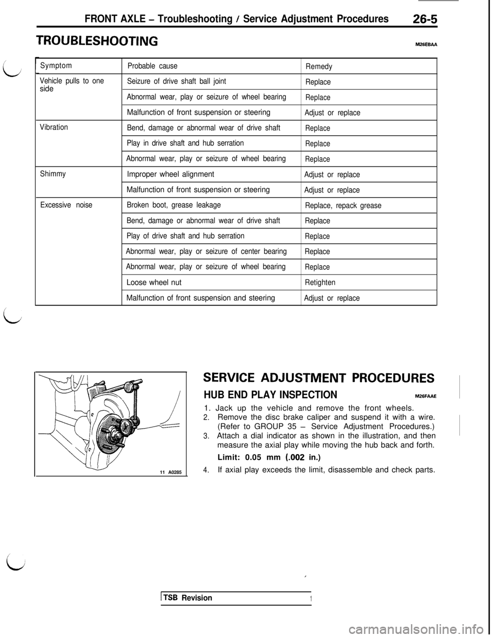
HUB END PLAY INSPECTIONM26FAAE1. Jack up the vehicle and remove the front wheels.
2.Remove the disc brake caliper and suspend it with a wire.
(Refer to GROUP 35
- Service Adjustment Procedures.)
3.Attach a dial indicator as shown in the illustration, and then
measure the axial play while moving the hub back and forth.
Limit: 0.05 mm (.002 in.)
4.If axial play exceeds the limit, disassemble and check parts.
,
1 TSB Revision1
i
Page 582 of 1146
26-6FRONT AXLE - Hub and Knuckle
HUB AND KNUCKLE
REMOVAL AND INSTALLATION
M261A- -
- 105 Nm
7 - 76 fubs.
60-72Nm2001260 Nm
43 - 52 ft.‘bs.145 - 188 ftlbs.b
Ibs.UN002929Nm
200
- 260 Nm145- 188 ftlbs.llFO026
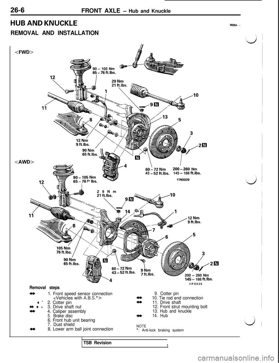
Removal steps
4*1. Front speed sensor connection
l *2. Cotter pin4* l +3. Drive shaft nut4*4. Caliper assembly5.Brake disc6. Front hub unit bearing7.Dust shield4*8. Lower arm ball joint connection
4*4*
4*
9.Cotterpin10. Tie rod end connection
11. Drive shaft
12. Front strut mounting bolt
13. Hub and knuckle14.Hub
NOTE*: Anti-lock braking system
TSB Revision1
Page 583 of 1146
FRONT AXLE - Hub and Knuckle26-7MB990998-01MB990635-01
II
I1 lA0286 1
SERVICE POINTS OF REMOVALM2618AH
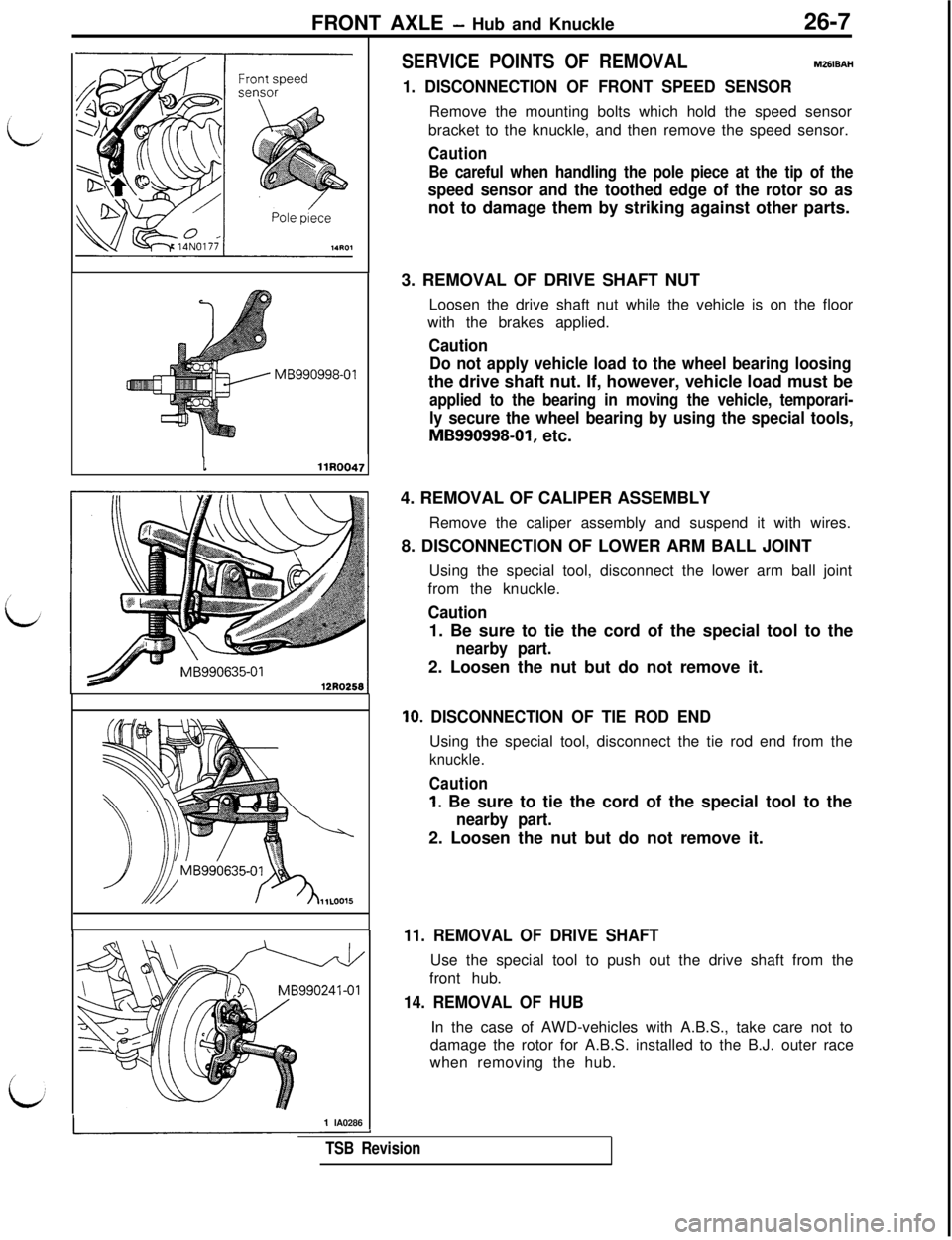
1. DISCONNECTION OF FRONT SPEED SENSORRemove the mounting bolts which hold the speed sensor
bracket to the knuckle, and then remove the speed sensor.
Caution
Be careful when handling the pole piece at the tip of the
speed sensor and the toothed edge of the rotor so asnot to damage them by striking against other parts.
3. REMOVAL OF DRIVE SHAFT NUT
Loosen the drive shaft nut while the vehicle is on the floor
with the brakes applied.
Caution
Do not apply vehicle load to the wheel bearing loosingthe drive shaft nut. If, however, vehicle load must be
applied to the bearing in moving the vehicle, temporari-
ly secure the wheel bearing by using the special tools,
MB990998-01, etc.
4. REMOVAL OF CALIPER ASSEMBLY
Remove the caliper assembly and suspend it with wires.
8. DISCONNECTION OF LOWER ARM BALL JOINT
Using the special tool, disconnect the lower arm ball joint
from the knuckle.
Caution1. Be sure to tie the cord of the special tool to the
nearby part.2. Loosen the nut but do not remove it.
IO. DISCONNECTION OF TIE ROD ENDUsing the special tool, disconnect the tie rod end from the
knuckle.
Caution
1. Be sure to tie the cord of the special tool to the
nearby part.2. Loosen the nut but do not remove it.
11. REMOVAL OF DRIVE SHAFTUse the special tool to push out the drive shaft from the
front hub.
14. REMOVAL OF HUBIn the case of AWD-vehicles with A.B.S., take care not to
damage the rotor for A.B.S. installed to the B.J. outer race
when removing the hub.
TSB Revision
Page 584 of 1146
26-8FRONT AXLE - Hub and KnuckleI
INSPECTIONM26lCAEl Check the hub for cracks and spline for wear.
l Check the oil seal for damage.
l Check the knuckle for cracks.
l Check for defective bearing.
L)
NOTE
If the meshing of the wheel bearing outer race and the
knuckle, or of the wheel bearing inner race and the hub, is
loose, replace the bearing or damaged parts.
llFO041:ter
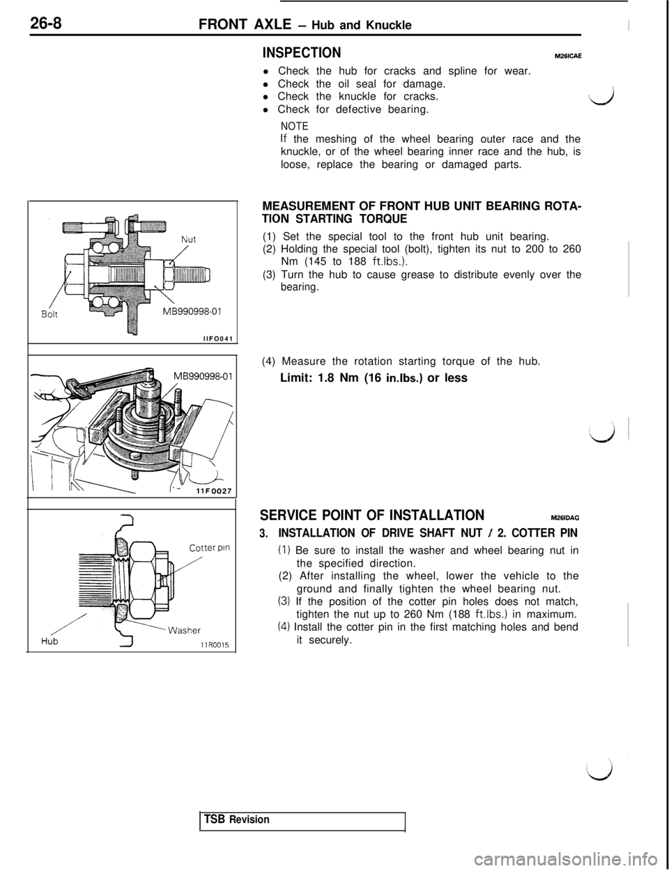
pinMEASUREMENT OF FRONT HUB UNIT BEARING ROTA-
TION STARTING TORQUE(1) Set the special tool to the front hub unit bearing.
(2) Holding the special tool (bolt), tighten its nut to 200 to 260
Nm (145 to 188 ft.lbs.).
(3) Turn the hub to cause grease to distribute evenly over the
bearing.(4) Measure the rotation starting torque of the hub.
Limit: 1.8 Nm (16
in.lbs.) or less
SERVICE POINT OF INSTALLATIONM261OAG
3.INSTALLATION OF DRIVE SHAFT NUT / 2. COTTER PIN
(I) Be sure to install the washer and wheel bearing nut in
the specified direction.
(2) After installing the wheel, lower the vehicle to the
ground and finally tighten the wheel bearing nut.
(3) If the position of the cotter pin holes does not match,
tighten the nut up to 260 Nm (188
ft.lbs.1 in maximum.
(4) Install the cotter pin in the first matching holes and bend
it securely.
TSB RevisionII
Page 585 of 1146
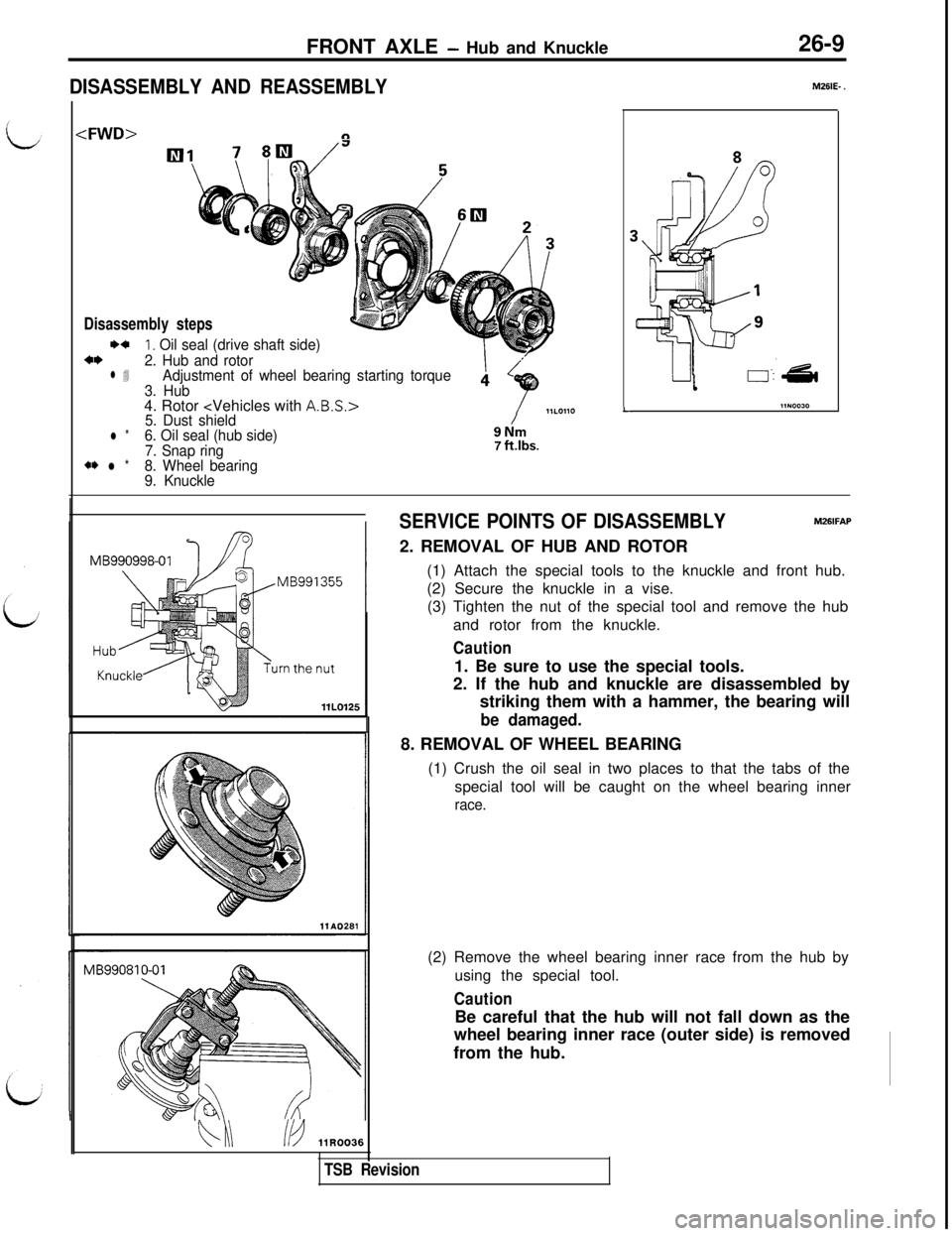
FRONT AXLE - Hub and Knuckle26-9
DISASSEMBLY AND REASSEMBLY
Disassembly stepsI)+
1. Oil seal (drive shaft side)*I)2. Hub and rotorl 4Adjustment of wheel bearing starting torque
3. Hub4. Rotor
5. Dust shieldl *6. Oil seal (hub side)
7. Snap ring
*I) l *8. Wheel bearing
9. Knuckle
/9Nm7 ftlbs.
L
MSIE- .
bi\/b ilR0036
SERVICE POINTS OF DISASSEMBLYM26lFAP2. REMOVAL OF HUB AND ROTOR
(1) Attach the special tools to the knuckle and front hub.
(2) Secure the knuckle in a vise.
(3) Tighten the nut of the special tool and remove the hub
and rotor from the knuckle.
Caution1. Be sure to use the special tools.
2. If the hub and knuckle are disassembled by
striking them with a hammer, the bearing will
be damaged.8. REMOVAL OF WHEEL BEARING
(1) Crush the oil seal in two places to that the tabs of the
special tool will be caught on the wheel bearing inner
race.(2) Remove the wheel bearing inner race from the hub by
using the special tool.
CautionBe careful that the hub will not fall down as the
wheel bearing inner race (outer side) is removed
from the hub.
TSB Revision
Page 586 of 1146
26-10
FRONT AXLE - Hub and KnuckleMB990938-01MB990932-01
/
llR00401 MB991355llL0124
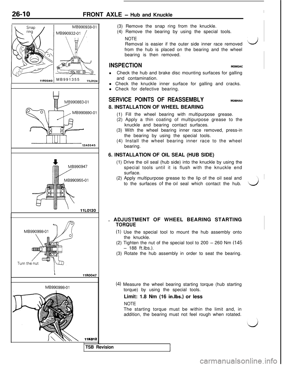
12A0545MB990998-01MB990998-01(3) Remove the snap ring from the knuckle.
(4) Remove the bearing by using the special tools.
NOTERemoval is easier if the outer side inner race removedLJfrom the hub is placed on the bearing and the wheel
bearing is then removed.
INSPECTIONM261GAC
lCheck the hub and brake disc mounting surfaces for galling
and contamination.
l Check the knuckle inner surface for galling and cracks.
l Check for defective bearing.
SERVICE POINTS OF REASSEMBLYMZBIHAO8. INSTALLATION OF WHEEL BEARING
(1) Fill the wheel bearing with multipurpose grease.
(2) Apply a thin coating of multipurpose grease to the
knuckle and bearing contact surfaces.
(3) With the wheel bearing inner race removed, press-in
the bearing by using the special tools.
(4) Install the wheel bearing inner race to the wheel
bearing.
6. INSTALLATION OF OIL SEAL (HUB SIDE)
(1) Drive the oil seal (hub side) into the knuckle by using the
special tools until it is flush with the knuckle end
surface.
(2) Apply multipurpose grease to the lip of the oil seal and
_to the surfaces ot the 011 seal which contact the hub.d. ADJUSTMENT OF WHEEL BEARING STARTING
TORQUE
(I) Use the special tool to mount the hub assembly onto
the knuckle.
(2) Tighten the nut of the special tool to 200
- 260 Nm .(I45
- 188 ft.lbs.).
(3) Rotate the hub assembly in order to seat the bearing.llKO12
TSB Revision
(4) Measure the wheel bearing starting torque (hub starting
torque) by using the special tools.
Limit: 1.8 Nm (16
in.lbs.) or less
NOTEThe starting torque must be within the limit and, in
addition, the bearing must not feel rough when rotated.
Page 587 of 1146
FRONT AXLE - Hub and Knuckle / Drive Shaft26-11
MB99
MB990890-01
llR0034
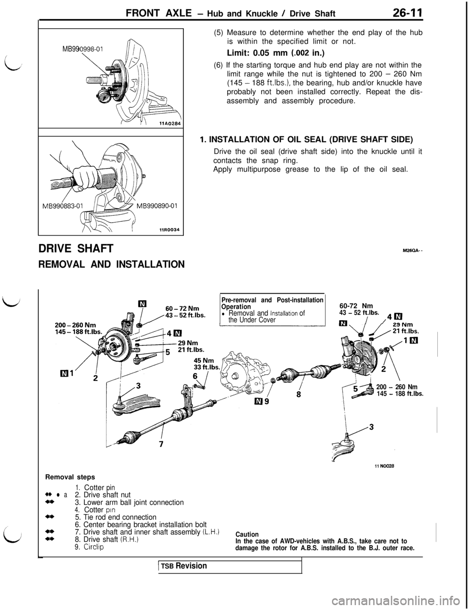
DRIVE SHAFT
REMOVAL AND INSTALLATIONRemoval steps(5) Measure to determine whether the end play of the hub
is within the specified limit or not.
Limit: 0.05 mm
(.002 in.)
(6) If the starting torque and hub end play are not within the
limit range while the nut is tightened to 200
- 260 Nm
(145
- 188 ft.lbs.), the bearing, hub and/or knuckle have
probably not been installed correctly. Repeat the dis-
assembly and assembly procedure.
1. INSTALLATION OF OIL SEAL (DRIVE SHAFT SIDE)
Drive the oil seal (drive shaft side) into the knuckle until it
contacts the snap ring.
Apply multipurpose grease to the lip of the oil seal.M26aA-
-
Pre-removal and Post-installation
60-72NmOperation60-72 Nm
/43-52ft.lbs.l Removal and lnstallatlon of43 - 52 ftlbs.the Under Covernl/ /40.
-I200 - 260 Nm
145 - 188 ftlbs.
1.Cotterpin+* l a2. Drive shaft nut4*3. Lower arm ball joint connection4.Cotterpin4*5. Tie rod end connection
6. Center bearing bracket installation bolt
4*7. Drive shaft and inner shaft assembly (L.H.14*8. Drive shaft (R.H.)
9.Circlip
11 NO026
Caution
In the case of AWD-vehicles with A.B.S., take care not to
damage the rotor for A.B.S. installed to the B.J. outer race.
1 TSB Revision
Page 588 of 1146
26-12FRONT AXLE - Drive Shaft
-01
M 8990635-0112R0258
llA0286i
llN0027
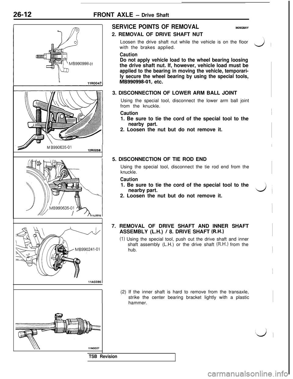
SERVICE POINTS OF REMOVALM26QBAY2. REMOVAL OF DRIVE SHAFT NUT
Loosen the drive shaft nut while the vehicle is on the floor
with the brakes applied.
Caution
Do not apply vehicle load to the wheel bearing loosingthe drive shaft nut. If, however, vehicle load must be
applied to the bearing in moving the vehicle, temporari-
ly secure the wheel bearing by using the special tools,
MB990998-01, etc.
3. DISCONNECTION OF LOWER ARM BALL JOINT
Using the special tool, disconnect the lower arm ball joint
from the knuckle.
Caution1. Be sure to tie the cord of the special tool to the
nearby part.2. Loosen the nut but do not remove it.
5. DISCONNECTION OF TIE ROD END
Using the special tool, disconnect the tie rod end from the
knuckle.
Caution1. Be sure to tie the cord of the special tool to the
nearby part.
2. Loosen the nut but do not remove it.
7. REMOVAL OF DRIVE SHAFT AND INNER SHAFT
ASSEMBLY (L.H.)
/ 8. DRIVE SHAFT (R.H.)
(I) Using the special tool, push out the drive shaft and inner
shaft assembly (L.H.) or the drive shaft
(R.H.) from the
hub.(2) If the inner shaft is hard to remove from the transaxle,
strike the center bearing bracket lightly with a plastic
hammer.
‘\
L+i
TSB Revision
Page 589 of 1146
FRONT AXLE - Drive Shaft26-13
llE53C
HI/JbCotter pm
/‘Washer
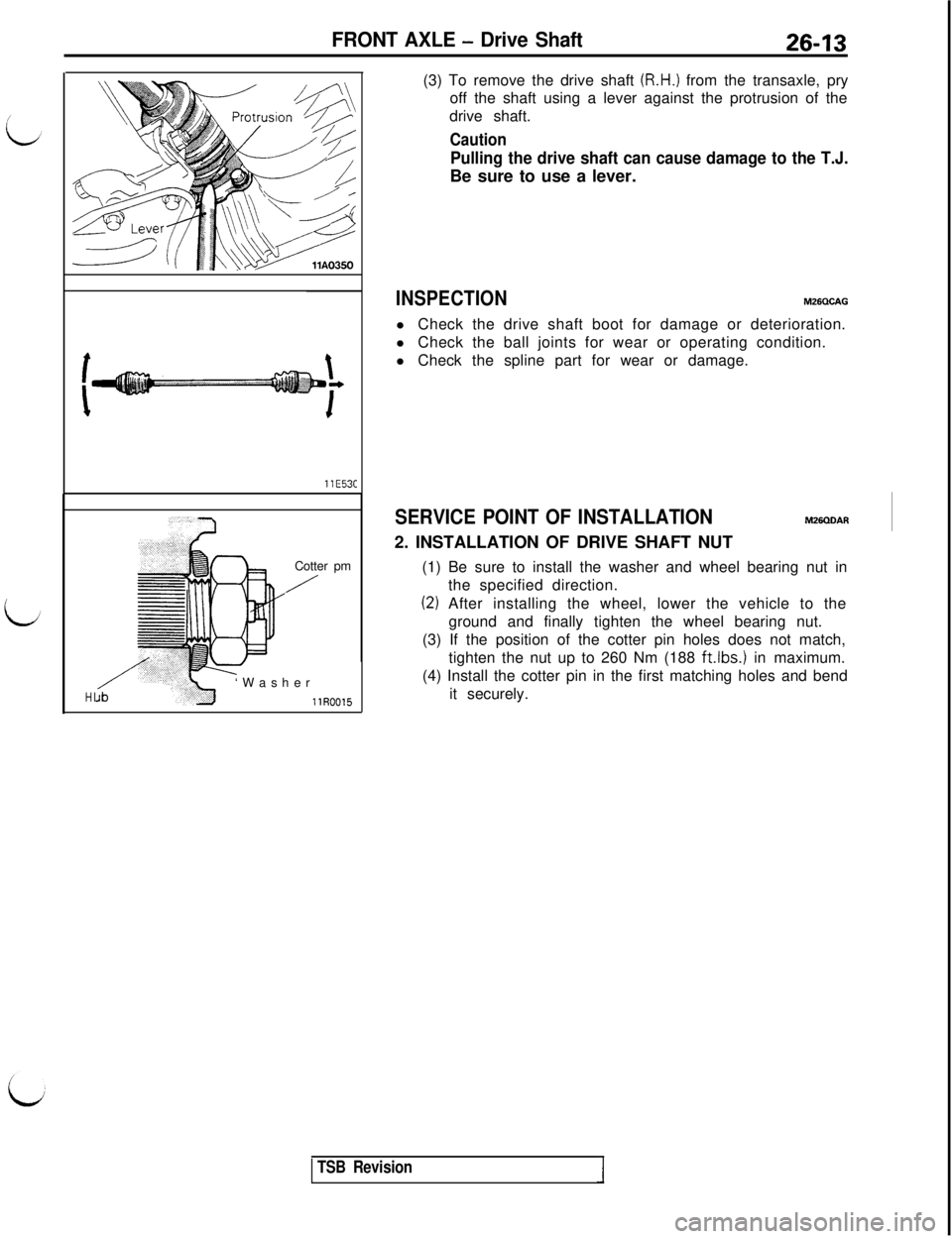
llR0015(3) To remove the drive shaft
(R.H.) from the transaxle, pry
off the shaft using a lever against the protrusion of the
drive shaft.
Caution
Pulling the drive shaft can cause damage to the T.J.Be sure to use a lever.
INSPECTIONM26QCAGl Check the drive shaft boot for damage or deterioration.
l Check the ball joints for wear or operating condition.
l Check the spline part for wear or damage.
SERVICE POINT OF INSTALLATIONM26QLlAR2. INSTALLATION OF DRIVE SHAFT NUT
(1) Be sure to install the washer and wheel bearing nut in
the specified direction.
(2) After installing the wheel, lower the vehicle to the
ground and finally tighten the wheel bearing nut.
(3) If the position of the cotter pin holes does not match,
tighten the nut up to 260 Nm (188
ft.lbs.1 in maximum.
(4) Install the cotter pin in the first matching holes and bend
it securely.
TSB Revision
Page 590 of 1146
26-14FRONT AXLE - Drive Shaft
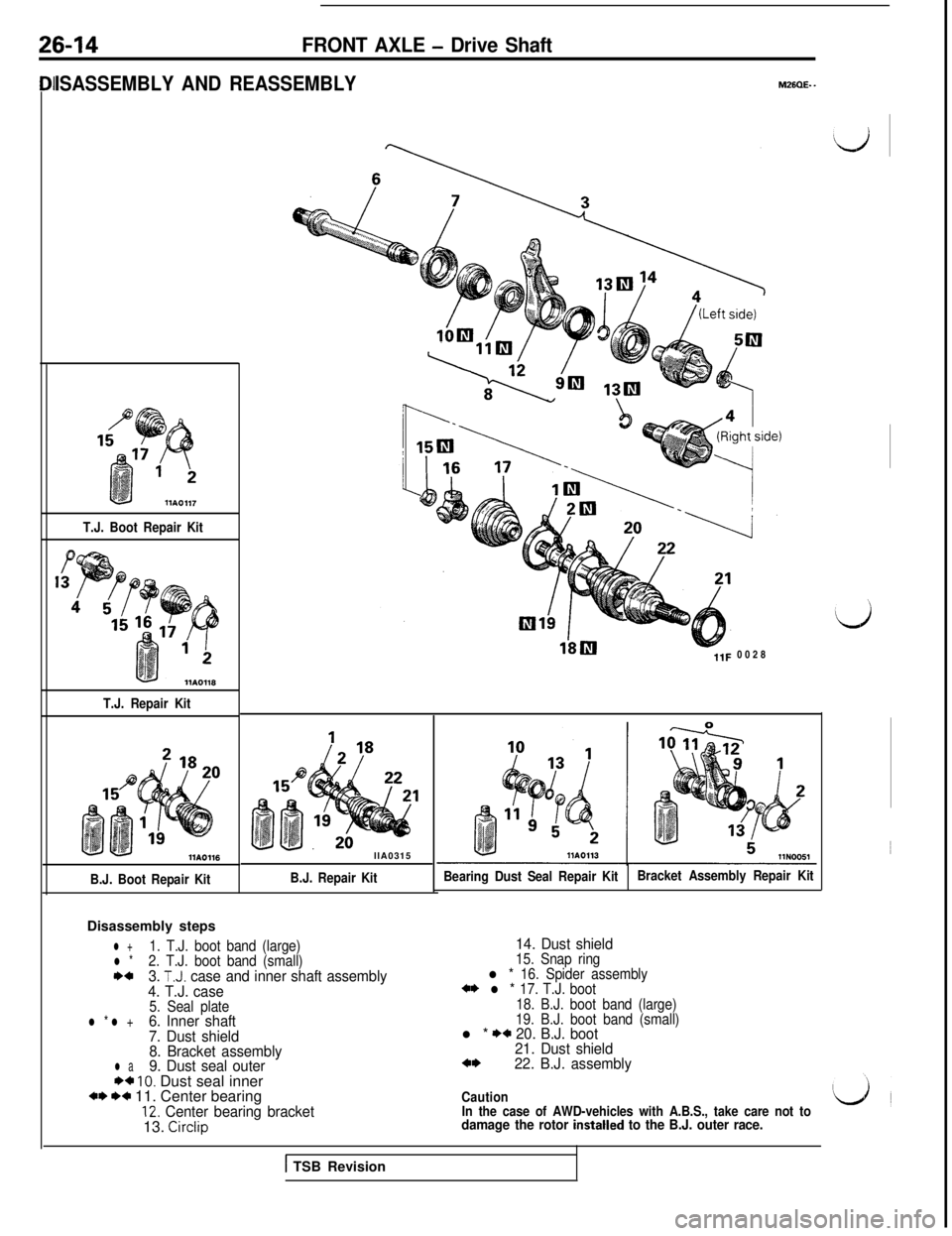
ISASSEMBLY AND REASSEMBLY
T.J. Boot Repair Kit
T.J. Repair KitllA0116
B.J. Boot Repair KitDisassembly stepsllA0315B.J. Repair Kit
l +1. T.J. boot band (large)l *2. T.J. boot band (small)I)+3. T.J. case and inner shaft assembly
4. T.J. case
5. Seal platel * l +6. Inner shaft
7. Dust shield
8. Bracket assembly
l a9. Dust seal outer** 10. Dust seal innerw W+ 11. Center bearing12. Center bearing bracket13. Circlip
M26QE- -0028
Bearing Dust Seal Repair KitBracket Assembly Repair Kit
14. Dust shield15. Snap ringl * 16. Spider assembly*I) l * 17. T.J. boot
18. B.J. boot band (large)
19. B.J. boot band (small)
l * I)* 20. B.J. boot
21. Dust shield
a*22. B.J. assembly
Caution
In the case of AWD-vehicles with A.B.S., take care not to
damage the rotor instatted to the B.J. outer race.
1 TSB Revision